EP0467402A2 - Verriegelungsmechanismus mit innerer Verriegelung für elektrische Verbinder - Google Patents
Verriegelungsmechanismus mit innerer Verriegelung für elektrische Verbinder Download PDFInfo
- Publication number
- EP0467402A2 EP0467402A2 EP91112143A EP91112143A EP0467402A2 EP 0467402 A2 EP0467402 A2 EP 0467402A2 EP 91112143 A EP91112143 A EP 91112143A EP 91112143 A EP91112143 A EP 91112143A EP 0467402 A2 EP0467402 A2 EP 0467402A2
- Authority
- EP
- European Patent Office
- Prior art keywords
- lock
- pair
- connector
- plug
- block
- Prior art date
- Legal status (The legal status is an assumption and is not a legal conclusion. Google has not performed a legal analysis and makes no representation as to the accuracy of the status listed.)
- Withdrawn
Links
Images


Classifications
-
- H—ELECTRICITY
- H01—ELECTRIC ELEMENTS
- H01R—ELECTRICALLY-CONDUCTIVE CONNECTIONS; STRUCTURAL ASSOCIATIONS OF A PLURALITY OF MUTUALLY-INSULATED ELECTRICAL CONNECTING ELEMENTS; COUPLING DEVICES; CURRENT COLLECTORS
- H01R13/00—Details of coupling devices of the kinds covered by groups H01R12/70 or H01R24/00 - H01R33/00
- H01R13/62—Means for facilitating engagement or disengagement of coupling parts or for holding them in engagement
- H01R13/627—Snap or like fastening
- H01R13/6271—Latching means integral with the housing
- H01R13/6273—Latching means integral with the housing comprising two latching arms
Definitions
- the present invention relates generally to electrical connectors to be connected to ribbon or flat cables and, more particularly, to a lock mechanism for such electrical connectors.
- Fig. 12 shows a conventional electrical connector of this type.
- a connector plug c is connected and locked to a connector socket a by engaging a lock arm f of the plug c with a lock shoulder e of the socket a so that the pin receiving apertures b of the connector socket a receive the contact ping g of the connector plug c for providing electrical continuation.
- an electrical connector consisting of a connector socket having a rectangular socket block and a connector plug having a rectangular plug block.
- the rectangular socket block includes a pair of lock recesses on opposite sides thereof, each having a pair of lock shoulders and a cutout in a front portion thereof; and a pair of sloped surfaces in opposite front sides thereof.
- the rectangular plug block includes a pair of lock arms having a base portion extending backwardly from front ends of opposite sides of the plug block and a front portion extending backwardly and outwardly from the base portion, the base portions having a pair of lock projections; a pair of lock arm receiving recesses formed on opposite sides of the plug block; and a pair of end projections extending outwardly from a rear end of the plug block to define an end of the lock arm receiving recesses.
- the lock arms are depressed with two fingers to put in the lock arm receiving recesses, thereby reducing the width of the connector plug, resulting in the reduced connector size.
- the lock arms are inserted into the lock recesses without resistance and, when released, flex outwardly so that the lock projects engage the lock shoulders to lock the connector plug to the connector socket. Since the lock mechanism is of the inner lock type that lock projects engage the lock shoulder within the lock recesses, it is resistant to vibrations.
- the front portions of the lock arms project through the cutouts of the connector socket while the sloped surfaces of connector socket provides indentations sufficiently large to receive the fingers. Consequently, when the lock arms are depressed, the fingers rest in the indentations and engage the end projections of the connector socket so that it is easy to pull the connector plug out of the connector socket.
- an electrical connector consists of a connector socket 1 which is to be mounted on a board and a connector plug 2 which is to be connected to the connector socket 1.
- the connector socket 1 includes a socket block 3 made from a synthetic resin so as to have a plug cavity 4 which opens in the front end 3a.
- a number of terminals 5 are arranged at regular intervals lengthwise of the plug cavity 4.
- the contact portion 6 of each terminal 5 projects into the plug cavity 4 from the terminal support portion 4a of the socket block 3.
- the leg portion 7 of each terminal 5 projects outwardly from the rear wall 3d of the socket block 3 and is bent downwardly at right angles.
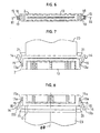
- a pair of lock recesses 8 each having a pair of lock shoulders 9 and 10 are formed on opposite side walls 3b and 3c of the socket block 3.
- Each side wall has a central cutout 11 in the front portion and a sloped surface 12.
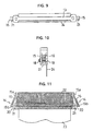
- the connector plug 2 includes a plug block 13 which is molded from a synthetic resin so as to have a pair of lock mechanisms 14 on opposites sides 13a.
- the lock mechanism 14 has a lock arm 15 which extends backwardly from the front end of the block side 13a.
- the lock arm 15 has a base portion 15a which extends parallel with the axis 8B and a front portion 15b which extends outwardly with respect to the axis 88.
- the front portion 15b is made thicker than the base portion 15a and is knurled on the outside 16 for preventing the finger from slipping.
- a pair of lock projections 18 and 19 are formed on opposite sides of the base portion 15a.
- a pair of lock arm receiving recesses 20 are formed on the side wills 13a (Fig. 11) for receiving the front portions 15b of the lock arms 15.
- a pair of end projections 21 project outwardly from the rear end of the plug block 13 providing the lock arm receiving recesses 20 with an end wall.
- a number of contact terminals 22 are arranged at regular intervals lengthwise of the plug block 13 and connected to a flat cable 23.
- the connector socket 1 is mounted on a board 24 by soldering the leg portions 6 of the terminals 5 to the through holes 25.
- the connector plug 2 is fitted into the plug cavity 4 of the connector socket 1 so that the contact terminals 22 are brought into contact with the contact portions 6 of the terminals 5 for providing electrical continuity.
- the lock arms 15 of the lock mechanisms 14 are depressed with two fingers to put them in the lock arm receiving recesses 20 so that the lock arms 15 are inserted into the lock recesses 8 without resistance. After insertion, the fingers are removed to release the lock arms 15 so that they flex outwardly with their own elasticity. Consequently, the lock projections 18 and 19 engage the lock shoulders 9 and 10 to lock the connector plug 2 to the connector socket 1.
- the front portions 15b of the lock arms 15 are depressed with two fingers to put them in the lock arm receiving recesses 20, thereby releasing the lock projections 18 and 19 from the lock shoulders 9 and 10 for removal of the connector plug 2 from the connector socket 1.
- the fingers rest in the indentations of the sloped surfaces 12 of the connector socket 1 coming into contact with the end projections 21. This makes it easy to pull the connector plug 2 out of the connector socket 1.
- the electrical connector according to the invention it is possible to reduce the width of the connector plug 2, thus minimizing the size of the electrical connector. Since the lock arms 15 are depressed into the receiving recesses 20 before locking, it is possible to insert the lock arms 15 into the lock recesses 8 without resistance. When released, the lock arms 15 flex outwardly so that the lock projections 18 and 19 of the lock arms 15 engage the lock shoulders 9 and 10 of the connector socket 1 to lock the connector plug 2 to the connector socket 1.
- This lock mechanism of the inner lock type in which the lock arms 15 engage within the lock recesses 20 is resistant to vibrations.
- the front portions of the lock arms 15 project through the cutouts 11 of the connector socket 1 while the sloped surfaces 12 provide indentations which are sufficiently large to receive the fingers.
- the fingers rest in the indentations of the sloped surfaces 12 of the connector socket 1 so that they engage the end projections 21 of the plug connector 2 without difficulty.
Landscapes
- Details Of Connecting Devices For Male And Female Coupling (AREA)
Applications Claiming Priority (1)
| Application Number | Priority Date | Filing Date | Title |
|---|---|---|---|
| JP1990076544U JPH0435370U (de) | 1990-07-20 | 1990-07-20 |
Publications (2)
| Publication Number | Publication Date |
|---|---|
| EP0467402A2 true EP0467402A2 (de) | 1992-01-22 |
| EP0467402A3 EP0467402A3 (en) | 1992-08-05 |
Family
ID=13608210
Family Applications (1)
| Application Number | Title | Priority Date | Filing Date |
|---|---|---|---|
| EP19910112143 Withdrawn EP0467402A3 (en) | 1990-07-20 | 1991-07-19 | Lock mechanism of inner lock type for electrical connector |
Country Status (3)
| Country | Link |
|---|---|
| US (1) | US5173059A (de) |
| EP (1) | EP0467402A3 (de) |
| JP (1) | JPH0435370U (de) |
Cited By (1)
| Publication number | Priority date | Publication date | Assignee | Title |
|---|---|---|---|---|
| CN103682809A (zh) * | 2013-11-25 | 2014-03-26 | 泰兴市航天电器有限公司 | 一种矩形电连接器用锁定机构 |
Families Citing this family (11)
| Publication number | Priority date | Publication date | Assignee | Title |
|---|---|---|---|---|
| US8109883B2 (en) | 2006-09-28 | 2012-02-07 | Tyco Healthcare Group Lp | Cable monitoring apparatus |
| US8668651B2 (en) | 2006-12-05 | 2014-03-11 | Covidien Lp | ECG lead set and ECG adapter system |
| CA2646037C (en) | 2007-12-11 | 2017-11-28 | Tyco Healthcare Group Lp | Ecg electrode connector |
| USD737979S1 (en) | 2008-12-09 | 2015-09-01 | Covidien Lp | ECG electrode connector |
| US8694080B2 (en) | 2009-10-21 | 2014-04-08 | Covidien Lp | ECG lead system |
| CA2746944C (en) | 2010-07-29 | 2018-09-25 | Tyco Healthcare Group Lp | Ecg adapter system and method |
| DK2734106T3 (da) | 2011-07-22 | 2020-01-06 | Kpr Us Llc | Ekg-elektrodekonnektor |
| US8634901B2 (en) | 2011-09-30 | 2014-01-21 | Covidien Lp | ECG leadwire system with noise suppression and related methods |
| US9408546B2 (en) | 2013-03-15 | 2016-08-09 | Covidien Lp | Radiolucent ECG electrode system |
| CN105120742B (zh) | 2013-03-15 | 2017-07-28 | 柯惠有限合伙公司 | 具有导电部件的电极连接器 |
| USD771818S1 (en) | 2013-03-15 | 2016-11-15 | Covidien Lp | ECG electrode connector |
Citations (4)
| Publication number | Priority date | Publication date | Assignee | Title |
|---|---|---|---|---|
| DE2646237A1 (de) * | 1975-10-13 | 1977-04-21 | Yamaichi Electric Mfg | Kupplungsvorrichtung fuer elektrische vater- und mutter-steckerverbindungen |
| GB2018048A (en) * | 1978-03-30 | 1979-10-10 | Nissan Motor | Electric Connector |
| US4458973A (en) * | 1983-01-28 | 1984-07-10 | Amp Incorporated | Connector assembly having improved internal latching system |
| US4681386A (en) * | 1986-01-22 | 1987-07-21 | Lance Wire And Cable, Inc. | Integral connector having plastic spring-clips |
Family Cites Families (4)
| Publication number | Priority date | Publication date | Assignee | Title |
|---|---|---|---|---|
| US3409859A (en) * | 1966-08-29 | 1968-11-05 | Molex Products Co | Separable electrical connector having rearwardly directed latch fingers |
| US3523269A (en) * | 1968-03-08 | 1970-08-04 | Essex International Inc | Panel locking terminal connector block |
| JPS5235777A (en) * | 1975-09-16 | 1977-03-18 | Dainippon Toryo Co Ltd | Radiation intensifying screen |
| US4406509A (en) * | 1981-11-25 | 1983-09-27 | E. I. Du Pont De Nemours & Co. | Jack and plug electrical assembly |
-
1990
- 1990-07-20 JP JP1990076544U patent/JPH0435370U/ja active Pending
-
1991
- 1991-07-19 EP EP19910112143 patent/EP0467402A3/en not_active Withdrawn
- 1991-07-19 US US07/731,788 patent/US5173059A/en not_active Expired - Fee Related
Patent Citations (4)
| Publication number | Priority date | Publication date | Assignee | Title |
|---|---|---|---|---|
| DE2646237A1 (de) * | 1975-10-13 | 1977-04-21 | Yamaichi Electric Mfg | Kupplungsvorrichtung fuer elektrische vater- und mutter-steckerverbindungen |
| GB2018048A (en) * | 1978-03-30 | 1979-10-10 | Nissan Motor | Electric Connector |
| US4458973A (en) * | 1983-01-28 | 1984-07-10 | Amp Incorporated | Connector assembly having improved internal latching system |
| US4681386A (en) * | 1986-01-22 | 1987-07-21 | Lance Wire And Cable, Inc. | Integral connector having plastic spring-clips |
Cited By (1)
| Publication number | Priority date | Publication date | Assignee | Title |
|---|---|---|---|---|
| CN103682809A (zh) * | 2013-11-25 | 2014-03-26 | 泰兴市航天电器有限公司 | 一种矩形电连接器用锁定机构 |
Also Published As
| Publication number | Publication date |
|---|---|
| EP0467402A3 (en) | 1992-08-05 |
| US5173059A (en) | 1992-12-22 |
| JPH0435370U (de) | 1992-03-24 |
Similar Documents
| Publication | Publication Date | Title |
|---|---|---|
| US4571017A (en) | Electrical connector assembly | |
| US5161985A (en) | Board to board interconnect | |
| US5310360A (en) | Circuit board mounted modular phone jack | |
| US4900261A (en) | Electrical connector system | |
| KR970004145B1 (ko) | 향상된 단자 보유 수단을 갖는 전기 커넥터 | |
| EP0305101B1 (de) | Verbindungsvorrichtung mit einem Teil mit kombinierter Abriegelung und Polarisation | |
| US4820198A (en) | In-line cable assembly, lock bar therefor | |
| US4433888A (en) | Printed circuit edgeboard connector with multi-function lock | |
| US5173059A (en) | Lock mechanism of inner lock type for electrical connector | |
| US5525072A (en) | Electrical connector assembly for interconnecting a flat cable to a circuit board | |
| US6244887B1 (en) | Electrical connector assembly | |
| US2928063A (en) | Electrical connector for printed circuit boards | |
| US5924891A (en) | Connector assembly for flat circuitry | |
| US4105275A (en) | Header with integral latch members | |
| JPS5929951B2 (ja) | 電気コネクタアセンブリ | |
| EP0467271B1 (de) | Aufbau eines elektrischen Verbinders | |
| US5119547A (en) | Means for separating male and female housings of an electric connector | |
| US6074230A (en) | Hermaphroditic electrical connectors | |
| US6162081A (en) | Electrical connector terminal arrangement | |
| US6764312B2 (en) | Connector for coupling panels and method of coupling panels using the connector | |
| EP0533970B1 (de) | Verriegelungsmechanismus mit innerer Verriegelung für elektrische Verbinder | |
| JP2607815B2 (ja) | フレキシブル・フラットケーブル | |
| US6146172A (en) | Electrical connector | |
| JP3865779B2 (ja) | 機械的結合装置 | |
| CN217009778U (zh) | 端子锁定件、连接器壳体组件和连接器组件 |
Legal Events
| Date | Code | Title | Description |
|---|---|---|---|
| PUAI | Public reference made under article 153(3) epc to a published international application that has entered the european phase |
Free format text: ORIGINAL CODE: 0009012 |
|
| AK | Designated contracting states |
Kind code of ref document: A2 Designated state(s): DE FR GB IT |
|
| PUAL | Search report despatched |
Free format text: ORIGINAL CODE: 0009013 |
|
| AK | Designated contracting states |
Kind code of ref document: A3 Designated state(s): DE FR GB IT |
|
| STAA | Information on the status of an ep patent application or granted ep patent |
Free format text: STATUS: THE APPLICATION IS DEEMED TO BE WITHDRAWN |
|
| 18D | Application deemed to be withdrawn |
Effective date: 19930206 |