EP0466910B1 - High energy ultrasonic lens with mounting facets - Google Patents
High energy ultrasonic lens with mounting facets Download PDFInfo
- Publication number
- EP0466910B1 EP0466910B1 EP91904638A EP91904638A EP0466910B1 EP 0466910 B1 EP0466910 B1 EP 0466910B1 EP 91904638 A EP91904638 A EP 91904638A EP 91904638 A EP91904638 A EP 91904638A EP 0466910 B1 EP0466910 B1 EP 0466910B1
- Authority
- EP
- European Patent Office
- Prior art keywords
- ultrasonic device
- transducers
- transducer
- ultrasonic
- curved support
- Prior art date
- Legal status (The legal status is an assumption and is not a legal conclusion. Google has not performed a legal analysis and makes no representation as to the accuracy of the status listed.)
- Expired - Lifetime
Links
- 239000000463 material Substances 0.000 claims description 13
- 230000005540 biological transmission Effects 0.000 claims description 7
- 239000004020 conductor Substances 0.000 claims description 6
- 230000005684 electric field Effects 0.000 claims description 6
- 239000004593 Epoxy Substances 0.000 claims description 5
- XAGFODPZIPBFFR-UHFFFAOYSA-N aluminium Chemical compound [Al] XAGFODPZIPBFFR-UHFFFAOYSA-N 0.000 claims description 4
- 229910052782 aluminium Inorganic materials 0.000 claims description 4
- 238000006243 chemical reaction Methods 0.000 claims description 2
- 239000002482 conductive additive Substances 0.000 claims description 2
- 239000004411 aluminium Substances 0.000 claims 2
- 238000001727 in vivo Methods 0.000 claims 2
- 239000013078 crystal Substances 0.000 description 5
- 238000003491 array Methods 0.000 description 3
- 239000012530 fluid Substances 0.000 description 3
- PEDCQBHIVMGVHV-UHFFFAOYSA-N Glycerine Chemical compound OCC(O)CO PEDCQBHIVMGVHV-UHFFFAOYSA-N 0.000 description 2
- 239000000919 ceramic Substances 0.000 description 2
- 230000002093 peripheral effect Effects 0.000 description 2
- 239000004575 stone Substances 0.000 description 2
- 238000002604 ultrasonography Methods 0.000 description 2
- XLYOFNOQVPJJNP-UHFFFAOYSA-N water Substances O XLYOFNOQVPJJNP-UHFFFAOYSA-N 0.000 description 2
- 239000004677 Nylon Substances 0.000 description 1
- 201000009310 astigmatism Diseases 0.000 description 1
- 230000015556 catabolic process Effects 0.000 description 1
- 230000015271 coagulation Effects 0.000 description 1
- 238000005345 coagulation Methods 0.000 description 1
- 239000012141 concentrate Substances 0.000 description 1
- 238000010276 construction Methods 0.000 description 1
- 238000007872 degassing Methods 0.000 description 1
- 238000007599 discharging Methods 0.000 description 1
- 239000002305 electric material Substances 0.000 description 1
- 230000003628 erosive effect Effects 0.000 description 1
- 239000000284 extract Substances 0.000 description 1
- 238000010304 firing Methods 0.000 description 1
- 235000011187 glycerol Nutrition 0.000 description 1
- 238000003384 imaging method Methods 0.000 description 1
- 238000009413 insulation Methods 0.000 description 1
- 239000012212 insulator Substances 0.000 description 1
- 239000012528 membrane Substances 0.000 description 1
- 229920001778 nylon Polymers 0.000 description 1
- 239000004033 plastic Substances 0.000 description 1
- 229920003023 plastic Polymers 0.000 description 1
- 239000000523 sample Substances 0.000 description 1
- 229910052709 silver Inorganic materials 0.000 description 1
- 239000004332 silver Substances 0.000 description 1
- 238000009211 ultrasonic lithotripsy Methods 0.000 description 1
Images


Classifications
-
- G—PHYSICS
- G10—MUSICAL INSTRUMENTS; ACOUSTICS
- G10K—SOUND-PRODUCING DEVICES; METHODS OR DEVICES FOR PROTECTING AGAINST, OR FOR DAMPING, NOISE OR OTHER ACOUSTIC WAVES IN GENERAL; ACOUSTICS NOT OTHERWISE PROVIDED FOR
- G10K11/00—Methods or devices for transmitting, conducting or directing sound in general; Methods or devices for protecting against, or for damping, noise or other acoustic waves in general
- G10K11/18—Methods or devices for transmitting, conducting or directing sound
- G10K11/26—Sound-focusing or directing, e.g. scanning
- G10K11/32—Sound-focusing or directing, e.g. scanning characterised by the shape of the source
-
- B—PERFORMING OPERATIONS; TRANSPORTING
- B06—GENERATING OR TRANSMITTING MECHANICAL VIBRATIONS IN GENERAL
- B06B—METHODS OR APPARATUS FOR GENERATING OR TRANSMITTING MECHANICAL VIBRATIONS OF INFRASONIC, SONIC, OR ULTRASONIC FREQUENCY, e.g. FOR PERFORMING MECHANICAL WORK IN GENERAL
- B06B1/00—Methods or apparatus for generating mechanical vibrations of infrasonic, sonic, or ultrasonic frequency
- B06B1/02—Methods or apparatus for generating mechanical vibrations of infrasonic, sonic, or ultrasonic frequency making use of electrical energy
- B06B1/06—Methods or apparatus for generating mechanical vibrations of infrasonic, sonic, or ultrasonic frequency making use of electrical energy operating with piezoelectric effect or with electrostriction
- B06B1/0607—Methods or apparatus for generating mechanical vibrations of infrasonic, sonic, or ultrasonic frequency making use of electrical energy operating with piezoelectric effect or with electrostriction using multiple elements
- B06B1/0622—Methods or apparatus for generating mechanical vibrations of infrasonic, sonic, or ultrasonic frequency making use of electrical energy operating with piezoelectric effect or with electrostriction using multiple elements on one surface
-
- G—PHYSICS
- G10—MUSICAL INSTRUMENTS; ACOUSTICS
- G10K—SOUND-PRODUCING DEVICES; METHODS OR DEVICES FOR PROTECTING AGAINST, OR FOR DAMPING, NOISE OR OTHER ACOUSTIC WAVES IN GENERAL; ACOUSTICS NOT OTHERWISE PROVIDED FOR
- G10K11/00—Methods or devices for transmitting, conducting or directing sound in general; Methods or devices for protecting against, or for damping, noise or other acoustic waves in general
- G10K11/18—Methods or devices for transmitting, conducting or directing sound
- G10K11/26—Sound-focusing or directing, e.g. scanning
- G10K11/30—Sound-focusing or directing, e.g. scanning using refraction, e.g. acoustic lenses
Definitions
- This invention relates to high energy ultrasonic devices which concentrate ultrasonic energy at an invivo target point for treating concrements and coagulations.
- Lithotripsy (stone-breaking) machines focus ultrasonic energy at stones (or other internal sites) for eroding the stone down to a size that can be passed by the patient.
- the ultrasonic energy is generated by piezoelectric crystal transducers mounted on a lens assembly.
- the transducers are internally stressed or “charged” by an intense electric field and discharged simultaneously to generate a collective pulse of ultrasonic energy.
- the crystal transducers were mounted on the back of a flat plate lens assembly which provided a flat mounting face for the transducers.
- the front of the lens assembly was a single large concave surface designed to focus the ultrasonic energy from all of the transducers at an invivo point within the patient.
- the simultaneous firing of the transducers promoted an "in phase" relationship between the individual pulse from each transducer, thereby increasing the pulse intensity of the collective pulse.
- transducers near the edge of the flat plate lens assembly had a longer ultrasound path length to the target region than transducers near the center.
- the energy pulses from the peripheral transducers arrived at the target region later.
- the resulting phase loss reduced the intensity of the collective pulse.
- a corrective curve for the lens assembly having a generaly elliptical or oblate shape was required to correct this peripheral astigmatism.
- the edge delay could not be corrected by using a simple concave curve with a true spherical shape.
- US-A-4 787 394 already discloses an ultrasound device of the type defined in the introductory part of claim 1.
- ultrasonic beam emitters are mounted on the concave inner surface of a curved support disk.
- the invention provides a device as defined in claim 1, and further embodiments are defined in the subclaims.
- a rigid curved support member which defines an invivo target region.
- the convex outer surface of the curved support member has a plurality of generally planar mounting facets formed thereon.
- a plurality of electric to ultrasonic transducers are mounted on outer surface of the support member.
- Each transducer has an inner mounting face which is generally planar for mounting onto one of the mounting facets.
- the major dimension of each transducer extends generally parallel to the underlying mounting facet, and the minor dimension extends generally normal to the underlying mounting facet.
- each transducer has an outer contact face for connection to a voltage.
- An electrical connector establishes an electric field across each transducer between the outer contact face and the inner mounting face for conversion into ultrasonic energy.
- the concave inner surface on the curved support has a plurality of focusing surfaces thereon, one focusing surface immediately opposed to each mounting facet on the outer surface.
- Each focusing surface forms an ultrasonic unit with the opposed mounting facet and the transducer mounted thereover to focus the ultrasonic energy from that transducer.
- Each element of the invention is designated by a two digit reference numeral.
- the first digit indicates the Figure in which that element is first disclosed or is primarily described.
- the second digit indicates like features and structural elements throughout the Figures.
- Some reference numerals are followed by a letter which indicates a subportion or feature of that element.
- High energy ultrasonic device 10 has a lens assembly 11 formed by an array of electrical to ultrasonic transducers 12 mounted on the convex outer surface of rigid, bowl shaped support member 13.
- the contour of the support member defines a focal depth or invivo target region 14.
- Patient 14P on an adjustable table 14T is positioned proximate to energy window 14W so that the invivo treatment site coincides with the target region.
- the space between the lens assembly and the patient contains a suitable transmission fluid 14F such as water, oil or glycerin, within rigid housing 14H.
- Flexible membrane 14M over the energy window permits fluid-to-patient interface.
- Crystal material within transducers 12 is periodically charged by a high voltage from voltage source 15V.
- the charging voltage is applied to each transducer by suitable electrical distribution leads such as conductive network 15N which is connected to one terminal of the voltage.
- support member 13 under the transducers is conductive and functions as the inner distribution conductor connected to the other terminal of the voltage.
- the applied voltage establishes an electrical field across each transducer crystal.
- the transducers are discharged rapidly by switching system 16.
- the individual pulse of ultrasonic energy from each transducer merges into a collective pulse which converges toward the target region becoming highly concentrated.
- Degassing system 17 continuously extracts gaseous material such as atmospheric air which has become dissolved or suspended in the transmission fluid.
- gaseous material such as atmospheric air which has become dissolved or suspended in the transmission fluid.
- the concentrated ultrasonic energy passing through the fluid causes gaseous material to form bubbles which diffuse or scatter the ultrasonic waves.
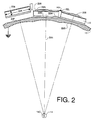
- the rear or external side of support member 13 has a convex surface machined to provide a plurality of planar mounting facets 23F.
- Each facet has a normal center line 23N perpendicular to the plane of the facet.
- the facets are orientated so that the center lines pass through a common center of curvature 14C in target region 14.
- the support member is symmetrically curved about a primary axis 13P which is preferably the normal center line through center transducer 32P (see Figure 3)
- Each transducer 12 has an inner mounting face 22M which engages one of the mounting facets 23F along a bond line 22B.
- Each transducer has a rear or outer electrode face 22E which electrically engages conductive mesh 25N by means of a suitable conductive medium such as conductive epoxy 25E.
- the high voltage terminal (HV) of the charging voltage is connected to the conductive mesh, and the ground terminal is connected to the support member.
- Transducers 12 may be disk shaped with a major dimension 22A extending generally parallel to underlying mounting facet, and a minor dimension 22a extending generally normal to the mounting facet.
- each transducer is generally planar to match the flat surface of the underlying mounting facet producing a uniform thin bond line 22B.
- Thin bonds lines establish stronger bonds with a longer service life.
- thin bond lines have less electrical resistance and will dissipate less voltage during charging and discharging of the transducers.
- a conductive bond line may function as the inner electrical distribution conductor for non-conductive support members formed of insulative materials such as plastics or ceramics.
- the internal or target side of support member 13 is a large concave surface with a plurality of smaller concave lenses or focusing surfaces 23S machined thereon.
- Each of these small focusing lens is centered in front of an opposed flat mounting facet on the other side of the support member, and is symmetrical about an axis of symmetry which passes through common point 14C.
- Each lens 23S focuses the individual pulse of energy from a single transducer at target region 14, where the individual pulses merge into an intense collective pulse.
- the diameter of the concave lenses is much less than the focal depth of the support member, which reduces edge delay within an individual pulse. That is, the path length of the energy from the edge of a transducer, through the edge of the lens, to the target region is only slightly greater than the path length of the energy from the center of the transducer, through the center of the lens. This relative size and path length relationship permits the use of true spherical sector surfaces for the focusing surface without significant compromise of the in phase condition. If preferred, the lenses may be slightly oblate to further enhance the in phase relationship within the collective pulse. The curve of the support member may also be true or oblate depending on the correction requirements.
- An independent ultrasonic unit is formed by each focusing surface, the immediately opposed mounting facet, and the transducer mounted thereover for generating an individual pulse of ultrasonic energy to be focused at the target region.
- the transducer in each unit is preferably centered on the underlying facet; and the axis of symmetry for the focusing surface in each unit is coincident with the normal center line of the opposed mounting facet.
- the contour of the support member determines the distance from the support member to the target region.
- the size of the target region and the intensity of the ultrasonic energy focused therein is determined by the machine tolerances of the mounting facets and focusing surfaces. In general, a lens assembly with smaller target region tends to erode the invivo target down to a smaller residual size.
- a target region of about 1.5-2 mm is suitable for many applications.
- the transducer centers may be arranged in a pattern of concentric hexagons of increasing size around a center position 32P which may be a transducer or an adit port for an ultrasonic imaging probe.
- the transducers are round with their centers forming the hexagons.
- the number of transducers in each hexagon increases by an increment of six.
- the first hexagon around the center position has 6 transducers, the second hexagon has 12 transducers, etc.
- Adjacent transducers within the same hexagon are separated by intra-hexagon interstitial space 32H.
- Adjacent transducers of bordering hexagons are separated by inter-hexagon interstitial space 32B.
- the lens assembly is curved, not flat: causing the interstitial spaces to decrease as the size of the hexagons increase.
- the interstitial spaces have a wedge shaped cross section as shown in Figure 2.
- the spaces are narrower along the bottom near the support member, and wider at the top near the outer contact face of the transducers.
- a suitable resilient cushioning material such as wedge shaped lattice 22L extending throughout the transducer array may be employed to prevent adjacent transducers from banging against each other during generation of the ultrasonic energy.
- the cushioning material may be an insulator for isolating the high voltage on the outer contact face of the transducer from ground on the support member. Without suitable insulation, fringe breakdown may occur around the periphery of the transducer.
- the transducers may be operated as a single array, or they may be sectored to operate as several smaller arrays as shown in the embodiment of Figure 3.
- Center array 38A has three intersecting lines of transducers formed by the transducers at the vertices of the hexagons.
- Six symmetrical side arrays 38B, 38C, 38D, 38E, 38F and 38G are formed by the transducers between the lines of subarray 38A.
- the transducers of the center array are connected together and connected to the high voltage by three strip conductors 35A.
- Each of the six side arrays has a separate mesh and connector 35B, 35C, 35D, 35E, 35F and 35G for the high voltage, and may be activated independently.
- Insulating dividers 32B, 32C, 32D, 32E, 32F and 32G extends along the interstitial space between the sectors to isolate the high voltage applied to the activated sector from the inactivated sectors.
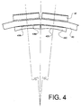
- Focusing caps 43C mounted along the inner concave surface of support member 43 may be employed to provide the focusing surface for the ultrasonic energy in place of the machined focusing surfaces 23S of the embodiment of Figure 2.
- the caps may be easily formed or machined prior to mounting within the lens assembly.
- the focusing surface may be either a true sphere or slightly oblate.
- Mounting surface 43M of the cap may be flat as shown or may be curved to facilitate bonding with the adjacent inner surface of the support member.
- the cap may be formed of any suitable material with an acoustic impedance close to the acoustic impedance of the support member.
- the material of the cap may be selected to enhance the acoustically match between the support and the transmission medium.
- the bond material within cap-to-support bond line 43B is thin to promote acoustical transfer.
- lens assembly 11 The following particulars of lens assembly 11 are given as an illustrative example of the present invention:
- Focusing Surface 23S - sector of a true sphere having curvature of about 12 ⁇ (30.5 cm) calculated from Snell's law: Rlen Rsup (1 - Vw/Va) where
- Insulative Cushion 22L - nylon wedge 100 mils (0.256 cm) across the top, 60 mils (0.154 cm across the bottom).
- the objects of this invention have been achieved by providing a lens assembly which produces less phase loss between the individual energy pulse from the transducers.
- the individual pulses arrive at the target region in a tighter group closer in time. Because of this enhanced phase condition, the lens assembly is more efficient and delivers the maximum pulse intensity with minimum operating voltage and lens area.
- the support member and focusing lenses may be simple curves having a true spherical surface to provide a simpler and less expensive lens assembly.
Landscapes
- Engineering & Computer Science (AREA)
- Physics & Mathematics (AREA)
- Acoustics & Sound (AREA)
- Multimedia (AREA)
- Mechanical Engineering (AREA)
- Surgical Instruments (AREA)
- Apparatuses For Generation Of Mechanical Vibrations (AREA)
- Ultra Sonic Daignosis Equipment (AREA)
- Transducers For Ultrasonic Waves (AREA)
Abstract
Description
- This invention relates to high energy ultrasonic devices which concentrate ultrasonic energy at an invivo target point for treating concrements and coagulations.
- Lithotripsy (stone-breaking) machines focus ultrasonic energy at stones (or other internal sites) for eroding the stone down to a size that can be passed by the patient. The ultrasonic energy is generated by piezoelectric crystal transducers mounted on a lens assembly. The transducers are internally stressed or "charged" by an intense electric field and discharged simultaneously to generate a collective pulse of ultrasonic energy.
- Heretofore, the crystal transducers were mounted on the back of a flat plate lens assembly which provided a flat mounting face for the transducers. The front of the lens assembly was a single large concave surface designed to focus the ultrasonic energy from all of the transducers at an invivo point within the patient. The simultaneous firing of the transducers promoted an "in phase" relationship between the individual pulse from each transducer, thereby increasing the pulse intensity of the collective pulse.
- However, transducers near the edge of the flat plate lens assembly had a longer ultrasound path length to the target region than transducers near the center. As a result of this edge delay, the energy pulses from the peripheral transducers arrived at the target region later. The resulting phase loss reduced the intensity of the collective pulse. A corrective curve for the lens assembly having a generaly elliptical or oblate shape was required to correct this peripheral astigmatism. The edge delay could not be corrected by using a simple concave curve with a true spherical shape.
- US-A-4 787 394 already discloses an ultrasound device of the type defined in the introductory part of claim 1. At this prior art device, ultrasonic beam emitters are mounted on the concave inner surface of a curved support disk.
- It is therefore an object of this invention to provide an improved high energy lens assembly.
- It is a further object of this invention to provide such a lens assembly which is more efficient and delivers higher pulse intensity with less operating voltage and lens area.
- It is a further object of this invention to provide such an efficient lens assembly which employs a simple curve having a true spherical surface.
- It is a further object of this invention to provide such a lens assembly which converges the ultrasonic energy with minimum edge delay.
- It is a further object of this invention to provide such a lens assembly that is simpler and less expensive.
- It is a further object of this invention to provide such a lens assembly which has a longer service life and is easier to maintain.
- It is a further object of this invention to provide such a lens assembly that may be operated in sectors.
- To achieve these objects, the invention provides a device as defined in claim 1, and further embodiments are defined in the subclaims.
- Briefly, these and other objects of the present invention are accomplished by providing a rigid curved support member which defines an invivo target region. The convex outer surface of the curved support member has a plurality of generally planar mounting facets formed thereon. A plurality of electric to ultrasonic transducers are mounted on outer surface of the support member. Each transducer has an inner mounting face which is generally planar for mounting onto one of the mounting facets. The major dimension of each transducer extends generally parallel to the underlying mounting facet, and the minor dimension extends generally normal to the underlying mounting facet. In addition, each transducer has an outer contact face for connection to a voltage. An electrical connector establishes an electric field across each transducer between the outer contact face and the inner mounting face for conversion into ultrasonic energy. The concave inner surface on the curved support has a plurality of focusing surfaces thereon, one focusing surface immediately opposed to each mounting facet on the outer surface. Each focusing surface forms an ultrasonic unit with the opposed mounting facet and the transducer mounted thereover to focus the ultrasonic energy from that transducer.
- Further objects and advantages of the present lens assembly and the convergence of the ultrasonic energy will become apparent from the following detailed description and drawing in which:
- FIGURE 1 is a schematic view of a general ultrasonic lithotripsy machine employing a high energy lens assembly;
- FIGURE 2 is a fragmentary sectional view of a lens assembly showing the outer mounting facets and the inner focusing surfaces;
- FIGURE 3 is a rear plan view of the transducer array showing the transducer centers arranged in a pattern of concentric hexagons with interstitial space between adjacent transducers; and
- FIGURE 4 is a sectional view of a transducer array having focusing caps mounted on the inside of the lens support in place of the machined surfaces of Figure 2.
- Each element of the invention is designated by a two digit reference numeral. The first digit indicates the Figure in which that element is first disclosed or is primarily described. The second digit indicates like features and structural elements throughout the Figures. Some reference numerals are followed by a letter which indicates a subportion or feature of that element.
- High energy
ultrasonic device 10 has alens assembly 11 formed by an array of electrical toultrasonic transducers 12 mounted on the convex outer surface of rigid, bowl shapedsupport member 13. The contour of the support member defines a focal depth orinvivo target region 14.Patient 14P on an adjustable table 14T is positioned proximate toenergy window 14W so that the invivo treatment site coincides with the target region. The space between the lens assembly and the patient contains asuitable transmission fluid 14F such as water, oil or glycerin, withinrigid housing 14H.Flexible membrane 14M over the energy window permits fluid-to-patient interface. - Crystal material within
transducers 12 is periodically charged by a high voltage fromvoltage source 15V. The charging voltage is applied to each transducer by suitable electrical distribution leads such asconductive network 15N which is connected to one terminal of the voltage. In the embodiment of Figure 1, supportmember 13 under the transducers is conductive and functions as the inner distribution conductor connected to the other terminal of the voltage. The applied voltage establishes an electrical field across each transducer crystal. The transducers are discharged rapidly by switchingsystem 16. The individual pulse of ultrasonic energy from each transducer merges into a collective pulse which converges toward the target region becoming highly concentrated. -
Degassing system 17 continuously extracts gaseous material such as atmospheric air which has become dissolved or suspended in the transmission fluid. The concentrated ultrasonic energy passing through the fluid causes gaseous material to form bubbles which diffuse or scatter the ultrasonic waves. - The rear or external side of
support member 13 has a convex surface machined to provide a plurality ofplanar mounting facets 23F. Each facet has anormal center line 23N perpendicular to the plane of the facet. The facets are orientated so that the center lines pass through a common center ofcurvature 14C intarget region 14. The support member is symmetrically curved about aprimary axis 13P which is preferably the normal center line throughcenter transducer 32P (see Figure 3) - Each
transducer 12 has aninner mounting face 22M which engages one of themounting facets 23F along abond line 22B. Each transducer has a rear orouter electrode face 22E which electrically engagesconductive mesh 25N by means of a suitable conductive medium such asconductive epoxy 25E. In the embodiment of Figure 2, the high voltage terminal (HV) of the charging voltage is connected to the conductive mesh, and the ground terminal is connected to the support member.Transducers 12 may be disk shaped with amajor dimension 22A extending generally parallel to underlying mounting facet, and aminor dimension 22a extending generally normal to the mounting facet. - The mounting face of each transducer is generally planar to match the flat surface of the underlying mounting facet producing a uniform
thin bond line 22B. Thin bonds lines establish stronger bonds with a longer service life. In addition, thin bond lines have less electrical resistance and will dissipate less voltage during charging and discharging of the transducers. - Voltage lost across the bond line reduces the applied high voltage from
source 15V that actually appears across the transducer crystals. The bond line voltage loss may be minimized further by the addition of a conductive additive such as silver to the epoxy. A conductive bond line may function as the inner electrical distribution conductor for non-conductive support members formed of insulative materials such as plastics or ceramics. - The internal or target side of
support member 13 is a large concave surface with a plurality of smaller concave lenses or focusingsurfaces 23S machined thereon. Each of these small focusing lens is centered in front of an opposed flat mounting facet on the other side of the support member, and is symmetrical about an axis of symmetry which passes throughcommon point 14C. Eachlens 23S focuses the individual pulse of energy from a single transducer attarget region 14, where the individual pulses merge into an intense collective pulse. - The diameter of the concave lenses is much less than the focal depth of the support member, which reduces edge delay within an individual pulse. That is, the path length of the energy from the edge of a transducer, through the edge of the lens, to the target region is only slightly greater than the path length of the energy from the center of the transducer, through the center of the lens. This relative size and path length relationship permits the use of true spherical sector surfaces for the focusing surface without significant compromise of the in phase condition. If preferred, the lenses may be slightly oblate to further enhance the in phase relationship within the collective pulse. The curve of the support member may also be true or oblate depending on the correction requirements.
- The radius of curvature of each spherical focusing surface is located along its axis of symmetry, and may be calculated from Snell's law for refraction of ultrasonic waves in a specific support member material and transmission medium:

where - Rlen
- = radius of curvature of the focusing surface
- Rsup
- = radius of curvature of the support member
- Vm
- = sonic velocity in transmission medium
- Vs
- = sonic velocity in support member material
- An independent ultrasonic unit is formed by each focusing surface, the immediately opposed mounting facet, and the transducer mounted thereover for generating an individual pulse of ultrasonic energy to be focused at the target region. The transducer in each unit is preferably centered on the underlying facet; and the axis of symmetry for the focusing surface in each unit is coincident with the normal center line of the opposed mounting facet. The unit focal point of each focusing surface in on the axis of symmetry thereof at a distance of Rlen.
- The contour of the support member determines the distance from the support member to the target region. The size of the target region and the intensity of the ultrasonic energy focused therein is determined by the machine tolerances of the mounting facets and focusing surfaces. In general, a lens assembly with smaller target region tends to erode the invivo target down to a smaller residual size. A target region of about 1.5-2 mm is suitable for many applications.
- The transducer centers may be arranged in a pattern of concentric hexagons of increasing size around a
center position 32P which may be a transducer or an adit port for an ultrasonic imaging probe. In the embodiment of Figure 3, the transducers are round with their centers forming the hexagons. The number of transducers in each hexagon increases by an increment of six. The first hexagon around the center position has 6 transducers, the second hexagon has 12 transducers, etc. - Adjacent transducers within the same hexagon are separated by intra-hexagon
interstitial space 32H. Adjacent transducers of bordering hexagons are separated by inter-hexagoninterstitial space 32B. The lens assembly is curved, not flat: causing the interstitial spaces to decrease as the size of the hexagons increase. - The interstitial spaces have a wedge shaped cross section as shown in Figure 2. The spaces are narrower along the bottom near the support member, and wider at the top near the outer contact face of the transducers. A suitable resilient cushioning material such as wedge shaped
lattice 22L extending throughout the transducer array may be employed to prevent adjacent transducers from banging against each other during generation of the ultrasonic energy. The cushioning material may be an insulator for isolating the high voltage on the outer contact face of the transducer from ground on the support member. Without suitable insulation, fringe breakdown may occur around the periphery of the transducer. - The transducers may be operated as a single array, or they may be sectored to operate as several smaller arrays as shown in the embodiment of Figure 3.
Center array 38A has three intersecting lines of transducers formed by the transducers at the vertices of the hexagons. Sixsymmetrical side arrays subarray 38A. The transducers of the center array are connected together and connected to the high voltage by three strip conductors 35A. Each of the six side arrays has a separate mesh andconnector dividers - Focusing
caps 43C mounted along the inner concave surface ofsupport member 43 may be employed to provide the focusing surface for the ultrasonic energy in place of the machined focusingsurfaces 23S of the embodiment of Figure 2. The caps may be easily formed or machined prior to mounting within the lens assembly. The focusing surface may be either a true sphere or slightly oblate. Mountingsurface 43M of the cap may be flat as shown or may be curved to facilitate bonding with the adjacent inner surface of the support member. The cap may be formed of any suitable material with an acoustic impedance close to the acoustic impedance of the support member. The material of the cap may be selected to enhance the acoustically match between the support and the transmission medium. Preferably, the bond material within cap-to-support bond line 43B is thin to promote acoustical transfer. - The following particulars of
lens assembly 11 are given as an illustrative example of the present invention: - Support Member 13 - sector of 16˝ (40.6 cm) true sphere, area of about 1200 sq cm, made of aluminum with an anodized surface.
- Mounting
Facets 23F - about 2˝ (5.08 cm) in diameter. - Transducers 12 - 60 disks 2˝ (5.08 cm) in diameter and one half inch (1.27 cm) thick, made of ceramic piezo electric material such as lead zirconate and capable of sustaining an electric field of about 20 volts per mil of thickness.
- Focusing
Surface 23S - sector of a true sphere having curvature of about 12˝ (30.5 cm) calculated from Snell's law:
where - Rlen
- = radius of curvature of the focusing face
- Rsup
- = radius of curvature of support surface
- Vw
- = sonic velocity of transmission water
- Va
- = sonic velocity of aluminum support.
-
Insulative Cushion 22L - nylon wedge,
100 mils (0.256 cm) across the top,
60 mils (0.154 cm across the bottom). - High Voltage - about 10,000 volts.
- The values, dimensions and material given above are not intended as defining the limitations of the invention. Numerous other constructions and configurations are possible.
- It will be apparent to those skilled in the art that the objects of this invention have been achieved by providing a lens assembly which produces less phase loss between the individual energy pulse from the transducers. The individual pulses arrive at the target region in a tighter group closer in time. Because of this enhanced phase condition, the lens assembly is more efficient and delivers the maximum pulse intensity with minimum operating voltage and lens area. The support member and focusing lenses may be simple curves having a true spherical surface to provide a simpler and less expensive lens assembly.
The radius of curvature of the concave focusing surface is always less than the radius of curvature of the support member because of a the relative sonic velocities Vm and Vs. However, the ultrasonic energy is focused at a common center of
Claims (33)
- A high energy ultrasonic device (10), for in vivo treatment, comprising:
a rigid curved support means (13) for defining an in vivo target region (14);
a plurality of electric to ultrasonic transducers (12) mounted on the curved support means (13), each transducer (12) having a major dimension (22A) extending generally parallel to the underlying mounting portion of said curved support means (13) and a minor dimension (22a) extending generally normal to the underlying mounting portion; and
electrical connector means (25N, HV, 15N) for connecting the transducers (12) to a voltage (15V) and for establishing an electric field across each transducer (12) for conversion into ultrasonic energy;
a concave inner surface on the curved support means (13) having a plurality of focusing means (23S, 43C) thereon;
characterized by a convex outer mounting surface on the curved support means (13) having a plurality of generally planar mounting facets (23F) formed thereon;
said transducers (12) mounted directly on the convex outer surface of the curved support means (13), each transducer (12) having an inner mounting face (22M), which is generally planar for mounting onto one of the mounting facets (22F), and each transducer (12) having an outer contact face (22E) for connection to said voltage (15V), said electric field across each transducer (12) being established between the outer contact surface (22E) and the inner mounting face (22M) of the transducer; and
one focusing means (23S, 43C) immediately opposed to each mounting facet (23P) on the outer mounting surface, each focusing means (23S, 43C) forming an ultrasonic unit with the opposed mounting facet (23F) and the transducer (12) mounted thereover to focus the ultrasonic energy from the transducers. - The ultrasonic device of claim 1, characterized in that each transducer-facet-focusing ultrasonic unit is identical to the other ultrasonic units.
- The ultrasonic device of claim 2, characterized in that each of the transducers (12) is a round disk.
- The ultrasonic device of claim 3, characterized in that the round disk transducers (12) are arranged in a pattern of concentric hexagons of increasing size.
- The ultrasonic device of claim 4, characterized in that the pattern of concentric hexagons increases in size in increments of six transducers.
- The ultrasonic device of claim 4, characterized in that the pattern of concentric hexagons has a first hexagon containing 6 transducers, and a second hexagon containing 12 transducers, and a third hexagon containing 18 transducers, and a fourth hexagon containing 24 transducers.
- The ultrasonic device of claim 6, characterized in that the pattern of concentric hexagons has a center transducer (32P) inside the first hexagon.
- The ultrasonic device of claim 4, characterized in that each disk transducer is separated from the adjacent transducers in the same hexagon forming an intra-hexagon interstitial space (32H), and separated from the adjacent transducers in the bordering hexagons forming an inter-border interstitial space.
- The ultrasonic device of claim 8, characterized in that the inter-hexagon interstitial space diminishes slightly for each larger hexagon.
- The ultrasonic device of claim 5, further characterized by a resilient cushion means (22L) in the interstitial space between adjacent transducers (12).
- The ultrasonic device of claim 1, characterized in that the curved support means (13) is symmetrically curved about a primary axis (13P) which passes through the target region (14) defined by the curved support means (13).
- The ultrasonic device of claim 11, characterized in that the curved support means (13) is a segment of a true sphere with the target region (14) at the center of curvature thereof.
- The ultrasonic device of claim 11, characterized in that the curved support means (13) is a segment of an oblate sphere with the target region (14) at the center thereof.
- The ultrasonic device of claim 11, characterized in that the normal center axis (23N) of each mounting facet (23F) in each ultrasonic unit passes through a common point (14C) in the target region (14) defined by the curve of the curved support means (13).
- The ultrasonic device of claim 14, characterized in that the focusing means (23S, 43C) in each ultrasonic unit comprises a curved focusing surface (23S, 43S) for defining a unit focal point (14C) along the normal center axis (23N) of the ultrasonic unit.
- The ultrasonic device of claim 15, characterized in that the relationship between the radius of curvature Rlen of the focusing surface (23S, 43S) and the radius of curvature Rsup of the curved support member (13) is approximately
 Rlen = radius of curvature of the focusing surface,Rsup = radius of curvature of the support member,Vm = sonic velocity in transmission medium,
andVs = sonic velocity in support member material. - The ultrasonic device of claim 15, characterized in that the curved focusing surface (23S) in each ultrasonic unit is a curved surface formed on the concave inner surface of the curved support means (13).
- The ultrasonic device of claim 15, further characterized by a plurality of focusing caps (43C) mounted on the concave inner surface of the curved support means (13) proximate the mounting facet within each ultrasonic unit, each focusing cap having an inner mounting surface (43M) for engaging the concave inner surface of the curved support means, and each cap having a curved outer focal surface (43S) for defining a focal point along the center axis of the ultrasonic unit.
- The ultrasonic device of claim 15, characterized in that the curve of the focusing surface (23S, 43S) is a true sphere.
- The ultrasonic device of claim 15, characterized in that the curve of the focusing surface (23S, 43S) is an oblate sphere.
- The ultrasonic device of claim 1, characterized in that the electrical connector means further comprise
outer electrode means across the outer contact face (22E) of each transducer (12);
inner electrode means (22B) across the inner mounting face (22M) of each transducer (12);
outer distribution conductor means (15N) for connecting the outer electrode means to one terminal of an electric voltage (15V); and
inner distribution conductor means for connecting the inner electrode means to the other terminal of the electric voltage (15V). - The ultrasonic device of claim 21, characterized in that the outer electrode means is a conductive mesh (25N) extending over outer contact faces (22E) of the transducers (12) on the convex mounting surface of the curved support means (13).
- The ultrasonic device of claim 22, further characterized by a conductive epoxy (25E) for cementing the conductive mesh (25N) to the outer contact face (22E) of the transducers (12).
- The ultrasonic device of claim 21, characterized in that the that the curved support means (13) is conductive and forms the inner electrode means.
- The ultrasonic device of claim 24, characterized in that the that the curved support means (13) is formed of aluminium.
- The ultrasonic device of claim 24, characterized in that the that the curved support means (13) is formed of aluminium with an anodized layer thereover.
- The ultrasonic device of claim 21, characterized in that the that the transducers (12) are bonded to the curved support means (13) by an epoxy, and the inner electrode means is formed by a conductive additive to the epoxy.
- The ultrasonic device of claim 21, characterized in that the that the outer electrode means are connected to the high voltage side of the electric voltage (15V), and the inner electrode means is connected to the ground side of the electric voltage.
- The ultrasonic device of claim 21, characterized in that the that the plurality of transducers are divided into sectors (38A - 38G) with an inter-transducer space between adjacent sectors, and the outer distribution conductor means provides a separate connection (35B - 35G) from the one terminal of the electric voltage (15V) to each transducer sector.
- The ultrasonic device of claim 29, further characterized by insulative divider means (32B - 32G) in the inter-transducer space between adjacent transducer sectors.
- The ultrasonic device of claim 29, characterized in that the inter-transducer space has a wedge cross-section with the wide portion of the wedge proximate the outer electrode and the narrow portion proximate the inner electrode.
- The ultrasonic device of claim 29, characterized in that the transducers (12) are arranged in a pattern of hexagons of increasing size.
- The ultrasonic device of claim 32, characterized in that the sectors further comprise a central sector (38A) formed by the transducers (12) at the vertices of the hexagons in the pattern and six side sectors (38B - 38G) formed by the transducers (12) between the vertices.
Applications Claiming Priority (3)
| Application Number | Priority Date | Filing Date | Title |
|---|---|---|---|
| US476874 | 1990-02-08 | ||
| US07/476,874 US5050588A (en) | 1990-02-08 | 1990-02-08 | High energy ultrasonic lens assembly with mounting facets |
| PCT/US1991/000817 WO1991011960A1 (en) | 1990-02-08 | 1991-02-06 | High energy ultrasonic lens with mounting facets |
Publications (3)
| Publication Number | Publication Date |
|---|---|
| EP0466910A1 EP0466910A1 (en) | 1992-01-22 |
| EP0466910A4 EP0466910A4 (en) | 1992-09-02 |
| EP0466910B1 true EP0466910B1 (en) | 1995-08-30 |
Family
ID=23893610
Family Applications (1)
| Application Number | Title | Priority Date | Filing Date |
|---|---|---|---|
| EP91904638A Expired - Lifetime EP0466910B1 (en) | 1990-02-08 | 1991-02-06 | High energy ultrasonic lens with mounting facets |
Country Status (6)
| Country | Link |
|---|---|
| US (1) | US5050588A (en) |
| EP (1) | EP0466910B1 (en) |
| AT (1) | ATE127263T1 (en) |
| AU (1) | AU7306191A (en) |
| DE (1) | DE69112527T2 (en) |
| WO (1) | WO1991011960A1 (en) |
Families Citing this family (33)
| Publication number | Priority date | Publication date | Assignee | Title |
|---|---|---|---|---|
| DE3803275A1 (en) * | 1988-02-04 | 1989-08-17 | Dornier Medizintechnik | PIEZOELECTRIC SHOCK WAVE SOURCE |
| DE3932967A1 (en) * | 1989-10-03 | 1991-04-11 | Wolf Gmbh Richard | ULTRASONIC SHOCK WAVE CONVERTER |
| US5399158A (en) * | 1990-05-31 | 1995-03-21 | The United States Of America As Represented By The Secretary Of The Army | Method of lysing thrombi |
| US5677491A (en) * | 1994-08-08 | 1997-10-14 | Diasonics Ultrasound, Inc. | Sparse two-dimensional transducer array |
| FR2756447B1 (en) * | 1996-11-26 | 1999-02-05 | Thomson Csf | MULTIPLE ELEMENT ACOUSTIC PROBE COMPRISING A COMMON MASS ELECTRODE |
| JP3331177B2 (en) * | 1998-07-29 | 2002-10-07 | 旭光学工業株式会社 | Sector scan ultrasound probe |
| US6310426B1 (en) * | 1999-07-14 | 2001-10-30 | Halliburton Energy Services, Inc. | High resolution focused ultrasonic transducer, for LWD method of making and using same |
| HU224572B1 (en) | 2002-11-05 | 2005-11-28 | Khaled Awad Saleh Nashwan | Device for treating patients suffering from haemal affection by a combination of infra-, audible- and ultrasound waves |
| US8473239B2 (en) * | 2009-04-14 | 2013-06-25 | Maui Imaging, Inc. | Multiple aperture ultrasound array alignment fixture |
| WO2007092054A2 (en) | 2006-02-06 | 2007-08-16 | Specht Donald F | Method and apparatus to visualize the coronary arteries using ultrasound |
| US20100262013A1 (en) * | 2009-04-14 | 2010-10-14 | Smith David M | Universal Multiple Aperture Medical Ultrasound Probe |
| EP2088932B1 (en) | 2006-10-25 | 2020-04-08 | Maui Imaging, Inc. | Method and apparatus to produce ultrasonic images using multiple apertures |
| US9282945B2 (en) | 2009-04-14 | 2016-03-15 | Maui Imaging, Inc. | Calibration of ultrasound probes |
| JP5666446B2 (en) | 2008-08-08 | 2015-02-12 | マウイ イマギング,インコーポレーテッド | Image forming method using multi-aperture medical ultrasonic technology and synchronization method of add-on system |
| WO2011103303A2 (en) | 2010-02-18 | 2011-08-25 | Maui Imaging, Inc. | Point source transmission and speed-of-sound correction using mult-aperture ultrasound imaging |
| EP2627257B1 (en) | 2010-10-13 | 2019-04-17 | Maui Imaging, Inc. | Concave ultrasound transducers and 3d arrays |
| WO2012051305A2 (en) | 2010-10-13 | 2012-04-19 | Mau Imaging, Inc. | Multiple aperture probe internal apparatus and cable assemblies |
| CN104105449B (en) | 2011-12-01 | 2018-07-17 | 毛伊图像公司 | Motion detection using acoustic pulse and multi-hole Doppler ultrasound |
| US9265484B2 (en) | 2011-12-29 | 2016-02-23 | Maui Imaging, Inc. | M-mode ultrasound imaging of arbitrary paths |
| CN107028623B (en) | 2012-02-21 | 2020-09-01 | 毛伊图像公司 | Determining Material Stiffness Using Porous Ultrasound |
| WO2013148673A1 (en) | 2012-03-26 | 2013-10-03 | Maui Imaging, Inc. | Systems and methods for improving ultrasound image quality by applying weighting factors |
| WO2014026185A1 (en) | 2012-08-10 | 2014-02-13 | Maui Imaging, Inc. | Calibration of multiple aperture ultrasound probes |
| KR102176319B1 (en) | 2012-08-21 | 2020-11-09 | 마우이 이미징, 인코포레이티드 | Ultrasound imaging system memory architecture |
| US20140064513A1 (en) | 2012-09-06 | 2014-03-06 | MUSIC Group IP Ltd. | System and method for remotely controlling audio equipment |
| US9510806B2 (en) | 2013-03-13 | 2016-12-06 | Maui Imaging, Inc. | Alignment of ultrasound transducer arrays and multiple aperture probe assembly |
| US9883848B2 (en) | 2013-09-13 | 2018-02-06 | Maui Imaging, Inc. | Ultrasound imaging using apparent point-source transmit transducer |
| JP6722656B2 (en) | 2014-08-18 | 2020-07-15 | マウイ イマギング,インコーポレーテッド | Network-based ultrasound imaging system |
| EP3277187B1 (en) | 2015-03-30 | 2022-05-04 | Maui Imaging, Inc. | Ultrasound imaging methods for detecting object motion |
| US10856846B2 (en) | 2016-01-27 | 2020-12-08 | Maui Imaging, Inc. | Ultrasound imaging with sparse array probes |
| AT521789B1 (en) * | 2019-05-16 | 2020-07-15 | Felix Trampler Dr | DEVICE FOR GENERATING A STANDING ULTRASONIC FIELD |
| JP7724853B2 (en) | 2020-10-21 | 2025-08-18 | マウイ イマギング,インコーポレーテッド | Systems and methods for tissue characterization using multiple aperture ultrasound |
| EP4236811A4 (en) | 2020-11-02 | 2024-10-09 | Maui Imaging, Inc. | SYSTEMS AND METHODS FOR ENHANCING ULTRASOUND IMAGE QUALITY |
| US12377017B2 (en) | 2021-10-27 | 2025-08-05 | Curative Sound, LLC | Handheld focused extracorporeal shock wave therapy device, kit, and method |
Family Cites Families (8)
| Publication number | Priority date | Publication date | Assignee | Title |
|---|---|---|---|---|
| US3587567A (en) * | 1968-12-20 | 1971-06-28 | Peter Paul Schiff | Mechanical ventricular assistance assembly |
| US3587561A (en) * | 1969-06-05 | 1971-06-28 | Hoffmann La Roche | Ultrasonic transducer assembly for biological monitoring |
| DE3319871A1 (en) * | 1983-06-01 | 1984-12-06 | Richard Wolf Gmbh, 7134 Knittlingen | PIEZOELECTRIC CONVERTER FOR DESTROYING CONCRETE IN THE BODY |
| US4562900A (en) * | 1984-12-20 | 1986-01-07 | Varian Associates, Inc. | Lens system for acoustic transducer array |
| US4865042A (en) * | 1985-08-16 | 1989-09-12 | Hitachi, Ltd. | Ultrasonic irradiation system |
| JPS6346147A (en) * | 1986-04-24 | 1988-02-27 | 株式会社東芝 | Ultrasonic remedy apparatus |
| EP0310380B2 (en) * | 1987-09-30 | 1997-04-02 | Kabushiki Kaisha Toshiba | Ultrasonic medical treatment apparatus |
| US4955366A (en) * | 1987-11-27 | 1990-09-11 | Olympus Optical Co., Ltd. | Ultrasonic therapeutical apparatus |
-
1990
- 1990-02-08 US US07/476,874 patent/US5050588A/en not_active Expired - Fee Related
-
1991
- 1991-02-06 AU AU73061/91A patent/AU7306191A/en not_active Abandoned
- 1991-02-06 DE DE69112527T patent/DE69112527T2/en not_active Expired - Fee Related
- 1991-02-06 AT AT91904638T patent/ATE127263T1/en not_active IP Right Cessation
- 1991-02-06 EP EP91904638A patent/EP0466910B1/en not_active Expired - Lifetime
- 1991-02-06 WO PCT/US1991/000817 patent/WO1991011960A1/en not_active Ceased
Also Published As
| Publication number | Publication date |
|---|---|
| AU7306191A (en) | 1991-09-03 |
| US5050588A (en) | 1991-09-24 |
| EP0466910A4 (en) | 1992-09-02 |
| EP0466910A1 (en) | 1992-01-22 |
| WO1991011960A1 (en) | 1991-08-22 |
| DE69112527D1 (en) | 1995-10-05 |
| ATE127263T1 (en) | 1995-09-15 |
| DE69112527T2 (en) | 1996-05-02 |
Similar Documents
| Publication | Publication Date | Title |
|---|---|---|
| US5050588A (en) | High energy ultrasonic lens assembly with mounting facets | |
| US6104126A (en) | Composite transducer with connective backing block | |
| EP0468506B1 (en) | Fixed origin biplane ultrasonic transducer | |
| EP0310380B2 (en) | Ultrasonic medical treatment apparatus | |
| US4640291A (en) | Bi-plane phased array for ultrasound medical imaging | |
| GB2232321A (en) | Focusing piezoelectric transducer | |
| US5706820A (en) | Ultrasonic transducer with reduced elevation sidelobes and method for the manufacture thereof | |
| EP0142215A2 (en) | Ultrasound transducer with improved vibrational modes | |
| EP0212737B1 (en) | Ultrasonic imaging apparatus | |
| WO1996039938A1 (en) | Phased array transducer design and method for manufacture thereof | |
| US5101133A (en) | Ultrasonic transducer having piezoelectric transducer elements | |
| JP2016072862A (en) | Ultrasonic sensor and probe and electronic equipment | |
| US5250869A (en) | Ultrasonic transducer | |
| US20220008754A1 (en) | Ultrasound emission device and ultrasound apparatus | |
| JPS6052823B2 (en) | Probe for ultrasound diagnostic equipment | |
| KR20200132475A (en) | Mask and skin care device including the same | |
| US11938514B2 (en) | Curved shape piezoelectric transducer and method for manufacturing the same | |
| JPH0871078A (en) | Ultrasonic generator | |
| JPS59202059A (en) | Probe for ultrasonic tomographic apparatus | |
| JP3354195B2 (en) | Ultrasonic probe device | |
| JPH0538335A (en) | Ultrasonic probe and method for manufacturing the same | |
| JPH06154233A (en) | Impact wave generator | |
| JPH04111599A (en) | Ultrasonic probe | |
| JPH01259699A (en) | Ultrasonic converter | |
| JPS6290141A (en) | Probe for ultrasonic diagnostic apparatus |
Legal Events
| Date | Code | Title | Description |
|---|---|---|---|
| PUAI | Public reference made under article 153(3) epc to a published international application that has entered the european phase |
Free format text: ORIGINAL CODE: 0009012 |
|
| AK | Designated contracting states |
Kind code of ref document: A1 Designated state(s): AT BE CH DE DK FR GB IT LI NL |
|
| 17P | Request for examination filed |
Effective date: 19920129 |
|
| A4 | Supplementary search report drawn up and despatched |
Effective date: 19920713 |
|
| AK | Designated contracting states |
Kind code of ref document: A4 Designated state(s): AT BE CH DE DK FR GB IT LI NL |
|
| 17Q | First examination report despatched |
Effective date: 19930909 |
|
| GRAA | (expected) grant |
Free format text: ORIGINAL CODE: 0009210 |
|
| AK | Designated contracting states |
Kind code of ref document: B1 Designated state(s): AT BE CH DE DK FR GB IT LI NL |
|
| PG25 | Lapsed in a contracting state [announced via postgrant information from national office to epo] |
Ref country code: IT Free format text: LAPSE BECAUSE OF FAILURE TO SUBMIT A TRANSLATION OF THE DESCRIPTION OR TO PAY THE FEE WITHIN THE PRE;WARNING: LAPSES OF ITALIAN PATENTS WITH EFFECTIVE DATE BEFORE 2007 MAY HAVE OCCURRED AT ANY TIME BEFORE 2007. THE CORRECT EFFECTIVE DATE MAY BE DIFFERENT FROM THE ONE RECORDED.SCRIBED TIME-LIMIT Effective date: 19950830 Ref country code: BE Effective date: 19950830 Ref country code: DK Effective date: 19950830 Ref country code: AT Effective date: 19950830 Ref country code: NL Free format text: LAPSE BECAUSE OF FAILURE TO SUBMIT A TRANSLATION OF THE DESCRIPTION OR TO PAY THE FEE WITHIN THE PRESCRIBED TIME-LIMIT Effective date: 19950830 |
|
| REF | Corresponds to: |
Ref document number: 127263 Country of ref document: AT Date of ref document: 19950915 Kind code of ref document: T |
|
| REF | Corresponds to: |
Ref document number: 69112527 Country of ref document: DE Date of ref document: 19951005 |
|
| ET | Fr: translation filed | ||
| NLV1 | Nl: lapsed or annulled due to failure to fulfill the requirements of art. 29p and 29m of the patents act | ||
| PLBE | No opposition filed within time limit |
Free format text: ORIGINAL CODE: 0009261 |
|
| STAA | Information on the status of an ep patent application or granted ep patent |
Free format text: STATUS: NO OPPOSITION FILED WITHIN TIME LIMIT |
|
| 26N | No opposition filed | ||
| PGFP | Annual fee paid to national office [announced via postgrant information from national office to epo] |
Ref country code: GB Payment date: 20000128 Year of fee payment: 10 |
|
| PGFP | Annual fee paid to national office [announced via postgrant information from national office to epo] |
Ref country code: FR Payment date: 20000224 Year of fee payment: 10 |
|
| PGFP | Annual fee paid to national office [announced via postgrant information from national office to epo] |
Ref country code: CH Payment date: 20000228 Year of fee payment: 10 |
|
| PGFP | Annual fee paid to national office [announced via postgrant information from national office to epo] |
Ref country code: DE Payment date: 20000420 Year of fee payment: 10 |
|
| PG25 | Lapsed in a contracting state [announced via postgrant information from national office to epo] |
Ref country code: GB Free format text: LAPSE BECAUSE OF NON-PAYMENT OF DUE FEES Effective date: 20010206 |
|
| PG25 | Lapsed in a contracting state [announced via postgrant information from national office to epo] |
Ref country code: CH Free format text: LAPSE BECAUSE OF NON-PAYMENT OF DUE FEES Effective date: 20010228 Ref country code: LI Free format text: LAPSE BECAUSE OF NON-PAYMENT OF DUE FEES Effective date: 20010228 |
|
| GBPC | Gb: european patent ceased through non-payment of renewal fee |
Effective date: 20010206 |
|
| REG | Reference to a national code |
Ref country code: CH Ref legal event code: PL |
|
| PG25 | Lapsed in a contracting state [announced via postgrant information from national office to epo] |
Ref country code: FR Free format text: LAPSE BECAUSE OF NON-PAYMENT OF DUE FEES Effective date: 20011031 |
|
| REG | Reference to a national code |
Ref country code: FR Ref legal event code: ST |
|
| PG25 | Lapsed in a contracting state [announced via postgrant information from national office to epo] |
Ref country code: DE Free format text: LAPSE BECAUSE OF NON-PAYMENT OF DUE FEES Effective date: 20011201 |