EP0466764B1 - An arrangement for controlling a linear motor - Google Patents
An arrangement for controlling a linear motor Download PDFInfo
- Publication number
- EP0466764B1 EP0466764B1 EP90905707A EP90905707A EP0466764B1 EP 0466764 B1 EP0466764 B1 EP 0466764B1 EP 90905707 A EP90905707 A EP 90905707A EP 90905707 A EP90905707 A EP 90905707A EP 0466764 B1 EP0466764 B1 EP 0466764B1
- Authority
- EP
- European Patent Office
- Prior art keywords
- slide
- section
- cavity
- piston
- pilot member
- Prior art date
- Legal status (The legal status is an assumption and is not a legal conclusion. Google has not performed a legal analysis and makes no representation as to the accuracy of the status listed.)
- Expired - Lifetime
Links
- 239000012530 fluid Substances 0.000 claims abstract description 31
- 230000000694 effects Effects 0.000 claims description 2
- 230000000717 retained effect Effects 0.000 abstract description 2
- 230000001419 dependent effect Effects 0.000 description 2
- 238000013459 approach Methods 0.000 description 1
- 239000007789 gas Substances 0.000 description 1
- 238000002347 injection Methods 0.000 description 1
- 239000007924 injection Substances 0.000 description 1
- 239000007788 liquid Substances 0.000 description 1
- 238000005086 pumping Methods 0.000 description 1
- 239000000126 substance Substances 0.000 description 1
- 238000005406 washing Methods 0.000 description 1
- XLYOFNOQVPJJNP-UHFFFAOYSA-N water Substances O XLYOFNOQVPJJNP-UHFFFAOYSA-N 0.000 description 1
Images


Classifications
-
- F—MECHANICAL ENGINEERING; LIGHTING; HEATING; WEAPONS; BLASTING
- F01—MACHINES OR ENGINES IN GENERAL; ENGINE PLANTS IN GENERAL; STEAM ENGINES
- F01B—MACHINES OR ENGINES, IN GENERAL OR OF POSITIVE-DISPLACEMENT TYPE, e.g. STEAM ENGINES
- F01B11/00—Reciprocating-piston machines or engines without rotary main shaft, e.g. of free-piston type
- F01B11/001—Reciprocating-piston machines or engines without rotary main shaft, e.g. of free-piston type in which the movement in the two directions is obtained by one double acting piston motor
Definitions
- the present invention relates to an arrangement in a fluid driven linear motor, for instance for operating a high pressure pump, comprising a cylinder and a piston the two opposite sides of which are being supplied with driving fluid from a slide valve device having a slide which is moved between its terminal positions in a slide chamber under the effect of an elongate pilot member which is moved in step with the movements of the piston, the slide being provided with an axially continuous cavity in which said pilot member is slidingly received and arranged to alternately bring the cavity in fluid communication with the ends of the slide chamber when the piston is at its terminal positions, the slide further being provided with means for the supply of driving fluid to the cavity.
- Such linear motors may be used for driving for instance pumps for high pressure washing machines, water jet cutting, injection and dosage of chemicals, hydraulic systems, or for pumping most types of liquids and gases.
- a linear motor of the type mentioned above is known from US patent 3.374.713.
- the connection between the pilot member and the piston has considerable axial lost motion so that the pilot member is moved only when the piston approaches its end positions. This results in impacts causing wear and noise.
- the slide valve device is dependent upon continuous leakage from the high pressure side to the low pressure side in order to function. This leakage must be increased for increasing operating speed.
- the motor also has relatively many moving parts.
- the aim of the present invention is to provide an arrangement of the type mentioned initially which makes it possible to achieve a quicker stroke rate in the linear motor and at the same time makes its structure simpler, less costly and more reliable.
- the rate of stroke of the motor may be increased in order thereby to yield improved performance for the same size and weight, and the increased rate of stroke, moreover, will also make it easier to dampen the noise from the driving fluid let out by the motor if this is e.g. compressed air.
- Fig. 1 shows an axial section through a high pressure pump driven by means of a linear motor controlled according to the invention.
- Fig. 2 shows in larger scale and partial section a slide for use in the linear motor of Fig. 1.
- Figs. 3 - 6 are schematic sections through the motor of Fig. 1 which illustrate the various stages of its control.
- a high pressure pump generally designated by 1.
- this comprises a high pressure piston 2, connected to a piston rod 3.
- a driving piston 4 Connected to the piston rod 3 is a driving piston 4 which, together with a cylinder 5, constitute the working parts of the linear motor.
- Through ducts 6 and 7 driving fluid is alternately added to and let out of the drive cylinder 5.
- a sliding valve device generally designated by 8. It comprises a slide 9, arranged slidingly in a slide chamber 10.
- the cylinder wall of the slide chamber is formed by a slide chamber sleeve 11, in which port openings are provided at mutually correct positions opposite to the various ducts of the sliding valve device.
- the slide 9 is equipped with an axially continuous cavity 12 which at its ends is terminated by means of a seal 13, respectively 14.
- the slide On its outside the slide has four sections of reduced diameter, designated 15, 16, 17, and 18, respectively.
- the middle two of these, 16 and 17, are active when driving fluid is added to and let out of the cylinder 5, while the outer two, 15 and 18, assist in supplying driving fluid to the internal cavity 12 of the slide, as will be explained in greater detail below.
- these sections are provided with radial bores 19 and 20.
- the sections of reduced diameter 15 - 18 are all confined by means of O-rings 21.
- a pilot rod 22 is fixedly connected to the piston rod in its continuation on the side opposite to the driving piston 4.
- the pilot rod will be glidingly received into the axially continuous cavity 12 of the slide 9, the diameter of the pilot rod and the seals 13 and 14 being adapted to each other so as to close the cavity 12 at its ends.
- the pilot rod 22 has an initial section 23 of reduced diameter. The length of this section is somewhat greater than the stroke of the slide 9, and the diameter is smaller than the internal diameter of the end seals 13 and 14 of the slide, so that when the section 23 is opposite to one or the other of these seals 13, 14, the internal cavity 12 of the slide will be open at the corresponding end of the slide.
- the pilot rod 22 is also provided with a second and a third section of reduced diameter, described respectively as 24 and 25. These sections will in a similar manner form openings past the seals in the end walls 26, 27 of the slide 9, when the piston 4 and thus the pilot rod 22 are at their terminal positions.
- the slide chamber 10 will be open directly to its ambient surroundings, while as far as the end wall 27 is concerned, it will be open to its ambient surroundings by means of a duct 28.
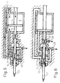
- Fig. 1 illustrates the linear motor according to the invention in the middle of a stroke.
- the direction of movement of the various parts and the driving fluid are indicated by arrows.
- the driving fluid is supplied to the slide valve device 8 through an inlet duct 29. It will be seen that this inlet duct has an internal side branch 30.
- the driving fluid flows from the inlet duct 29 through openings in the slide chamber sleeve 11 into a cavity defined by the slender section 17 of the slide 9 and out through openings in the sleeve 11 to the duct 6 and onwards to the drive cylinder 5 on the left-hand side of the piston 4.
- Driving fluid from the cylinder 5 on the right-hand side of the piston is forced out through the duct 7, through holes in the sleeve 11 into a cavity defined by the slender section 16 of the slide and through further holes in the sleeve 11 into an exhaust duct 31 leading to an appropriate place according to the application of the linear motor and the type of driving fluid employed.
- the slide 9 which, during the movement of the piston 4 to the right, is in its right-hand position, has its slender section 15 placed opposite to the side branch 30 of the inlet duct for the driving fluid. Consequently, this communicates with the internal cavity 12 of the slide through the bore 19 in the slide.
- FIG. 3 illustrates the same situation as fig. 1.
- driving fluid is supplied to the right-hand end of the slide chamber, to create a pressure against the right-hand end of the slide, forcing the slide to the left. While the slide makes this movement, driving fluid is constantly being supplied via the cavity 12 of the slide. During the initial part of the movement of the slide, the cavity 12 has driving fluid added through the bore 19 and the side branch 30, while during the latter part of the movement, the supply will be through the bore 20 in the slide and the inlet duct 29.
- the distance between the holes in the sleeve 11 of the slide chamber opposite to the inlet duct 29 and the side branch 30 is approximately equal to the distance between the outermost slender sections 15 and 18 of the slide 9.
- the left-hand side of the slide chamber 10 will be open during the entire movement of the slide to the left so that no resistance of pressure is created here, and because the slender section 23 of the pilot rod 22 is somewhat longer than the stroke of the slide, full pressure of driving fluid will exist on the right-hand side of the slide, even after the slide has completed its movement.
- FIG. 6 This situation is illustrated in Fig. 6.
- the third slender section 25 of the pilot rod 22 has arrived at a position opposite to the seal in the end wall 27 of the slide chamber, so that the left-hand end section of the slide chamber 10 is vented through the duct 28.
- the first slender section 23 is in a position opposite to the seal 13 in the left-hand end of the slide.
- driving fluid is added through the inlet duct 29, the bore 20 and the internal cavity 12 of the slide to the left-hand end section of the slide chamber 10, the end wall 26 of which is now closed to its surroundings by the pilot rod 22.
- the pressure being built up on the left-hand side of the slide thereby forces it towards the right, so that the situation as described in Fig. 3 is again reached, after which the cycle is repeated.
Landscapes
- Engineering & Computer Science (AREA)
- Mechanical Engineering (AREA)
- General Engineering & Computer Science (AREA)
- Actuator (AREA)
- Reciprocating Pumps (AREA)
- Apparatus For Radiation Diagnosis (AREA)
- Developing Agents For Electrophotography (AREA)
- Fittings On The Vehicle Exterior For Carrying Loads, And Devices For Holding Or Mounting Articles (AREA)
- Linear Motors (AREA)
Abstract
Description
- The present invention relates to an arrangement in a fluid driven linear motor, for instance for operating a high pressure pump, comprising a cylinder and a piston the two opposite sides of which are being supplied with driving fluid from a slide valve device having a slide which is moved between its terminal positions in a slide chamber under the effect of an elongate pilot member which is moved in step with the movements of the piston, the slide being provided with an axially continuous cavity in which said pilot member is slidingly received and arranged to alternately bring the cavity in fluid communication with the ends of the slide chamber when the piston is at its terminal positions, the slide further being provided with means for the supply of driving fluid to the cavity.
- Such linear motors may be used for driving for instance pumps for high pressure washing machines, water jet cutting, injection and dosage of chemicals, hydraulic systems, or for pumping most types of liquids and gases.
- A linear motor of the type mentioned above is known from US patent 3.374.713. In this motor the connection between the pilot member and the piston has considerable axial lost motion so that the pilot member is moved only when the piston approaches its end positions. This results in impacts causing wear and noise. The slide valve device is dependent upon continuous leakage from the high pressure side to the low pressure side in order to function. This leakage must be increased for increasing operating speed. The motor also has relatively many moving parts.
- The aim of the present invention is to provide an arrangement of the type mentioned initially which makes it possible to achieve a quicker stroke rate in the linear motor and at the same time makes its structure simpler, less costly and more reliable.
- This is achieved according to the invention by an arrangement of the type mentioned initially which is characterized in that the cavity of the slide at its axially separated ends is provided with inwardly protruding seals which interact with the pilot member, and that the pilot member has a first section of reduced cross section which opens the said cavity towards the respective end of the slide chamber when it is in a position opposite one or the other of the seals.
- By arranging the slide and pilot device in this manner, rapid and reliable shifting of the position of the slide is achieved without the need to use appreciable force or a complicated, noisy and costly mechanism which could wear or would have springs which might sag. The rate of stroke of the motor may be increased in order thereby to yield improved performance for the same size and weight, and the increased rate of stroke, moreover, will also make it easier to dampen the noise from the driving fluid let out by the motor if this is e.g. compressed air.
- Advantageous embodiments of the invention are defined in the dependent claims.
- To further the understanding of the invention it will be described below with reference to the exemplifying embodiment shown in the attached drawings.
- Fig. 1 shows an axial section through a high pressure pump driven by means of a linear motor controlled according to the invention.
- Fig. 2 shows in larger scale and partial section a slide for use in the linear motor of Fig. 1.
- Figs. 3 - 6 are schematic sections through the motor of Fig. 1 which illustrate the various stages of its control.
- In Fig. 1 is shown a high pressure pump, generally designated by 1. this comprises a high pressure piston 2, connected to a piston rod 3. Connected to the piston rod 3 is a
driving piston 4 which, together with acylinder 5, constitute the working parts of the linear motor. Throughducts drive cylinder 5. - Control of the flow of the driving fluid in the
ducts slide 9, arranged slidingly in aslide chamber 10. The cylinder wall of the slide chamber is formed by a slide chamber sleeve 11, in which port openings are provided at mutually correct positions opposite to the various ducts of the sliding valve device. - As will be further evident from Fig. 2, the
slide 9 is equipped with an axiallycontinuous cavity 12 which at its ends is terminated by means of aseal 13, respectively 14. On its outside the slide has four sections of reduced diameter, designated 15, 16, 17, and 18, respectively. The middle two of these, 16 and 17, are active when driving fluid is added to and let out of thecylinder 5, while the outer two, 15 and 18, assist in supplying driving fluid to theinternal cavity 12 of the slide, as will be explained in greater detail below. For this purpose, these sections are provided withradial bores 19 and 20. The sections of reduced diameter 15 - 18 are all confined by means of O-rings 21. - Reference is again made to Fig. 1. A
pilot rod 22 is fixedly connected to the piston rod in its continuation on the side opposite to thedriving piston 4. The pilot rod will be glidingly received into the axiallycontinuous cavity 12 of theslide 9, the diameter of the pilot rod and theseals cavity 12 at its ends. Thepilot rod 22 has aninitial section 23 of reduced diameter. The length of this section is somewhat greater than the stroke of theslide 9, and the diameter is smaller than the internal diameter of theend seals section 23 is opposite to one or the other of theseseals internal cavity 12 of the slide will be open at the corresponding end of the slide. - The
pilot rod 22 is also provided with a second and a third section of reduced diameter, described respectively as 24 and 25. These sections will in a similar manner form openings past the seals in theend walls slide 9, when thepiston 4 and thus thepilot rod 22 are at their terminal positions. In the case of theend wall 26, theslide chamber 10 will be open directly to its ambient surroundings, while as far as theend wall 27 is concerned, it will be open to its ambient surroundings by means of aduct 28. - Fig. 1 illustrates the linear motor according to the invention in the middle of a stroke. The direction of movement of the various parts and the driving fluid are indicated by arrows. The driving fluid is supplied to the slide valve device 8 through an
inlet duct 29. It will be seen that this inlet duct has aninternal side branch 30. The driving fluid flows from theinlet duct 29 through openings in the slide chamber sleeve 11 into a cavity defined by theslender section 17 of theslide 9 and out through openings in the sleeve 11 to theduct 6 and onwards to thedrive cylinder 5 on the left-hand side of thepiston 4. Driving fluid from thecylinder 5 on the right-hand side of the piston is forced out through theduct 7, through holes in the sleeve 11 into a cavity defined by the slender section 16 of the slide and through further holes in the sleeve 11 into anexhaust duct 31 leading to an appropriate place according to the application of the linear motor and the type of driving fluid employed. - The
slide 9 which, during the movement of thepiston 4 to the right, is in its right-hand position, has its slender section 15 placed opposite to theside branch 30 of the inlet duct for the driving fluid. Consequently, this communicates with theinternal cavity 12 of the slide through thebore 19 in the slide. - How the linear motor further works will be explained in greater detail with reference to Fig. 3 - 6. Here, Fig. 3 illustrates the same situation as fig. 1.
- In Fig. 4 the
piston 4 has arrived at its right-hand terminal position. This causes theslender section 23 of thepilot rod 22 to be positioned opposite to theseal 14 at the right-hand end of theslide 9. Consequently, flow communication is established between thecavity 12 of the slide and the right-hand end of theslide chamber 10, so that this is pressurized by the driving fluid. At the same time, theslender section 24 of thepilot rod 22 is in a position opposite to the seal in theend wall 26 of the slide chamber, so that an opening is created here which vents the left-hand end of theslide chamber 10 to the ambient surroundings. As indicated by the arrows in Fig. 4, driving fluid is supplied to the right-hand end of the slide chamber, to create a pressure against the right-hand end of the slide, forcing the slide to the left. While the slide makes this movement, driving fluid is constantly being supplied via thecavity 12 of the slide. During the initial part of the movement of the slide, thecavity 12 has driving fluid added through thebore 19 and theside branch 30, while during the latter part of the movement, the supply will be through the bore 20 in the slide and theinlet duct 29. For this purpose, the distance between the holes in the sleeve 11 of the slide chamber opposite to theinlet duct 29 and theside branch 30 is approximately equal to the distance between the outermost slender sections 15 and 18 of theslide 9. The left-hand side of theslide chamber 10 will be open during the entire movement of the slide to the left so that no resistance of pressure is created here, and because theslender section 23 of thepilot rod 22 is somewhat longer than the stroke of the slide, full pressure of driving fluid will exist on the right-hand side of the slide, even after the slide has completed its movement. - When the slide has arrived at its left-hand position as shown in Fig. 5, the direction of flow has been reversed in the
ducts piston 4 and thepilot rod 22 will move towards the left. The movement of the pilot rod causes thecavity 12 of the slide to close again at both ends, so that the pressure built up on the right-hand side of the slide remains trapped and ensures that the slide is retained in its left-hand position until thepiston 4 has reached its left-hand position. - This situation is illustrated in Fig. 6. Here the
third slender section 25 of thepilot rod 22 has arrived at a position opposite to the seal in theend wall 27 of the slide chamber, so that the left-hand end section of theslide chamber 10 is vented through theduct 28. At the same time, thefirst slender section 23 is in a position opposite to theseal 13 in the left-hand end of the slide. This entails that driving fluid is added through theinlet duct 29, the bore 20 and theinternal cavity 12 of the slide to the left-hand end section of theslide chamber 10, theend wall 26 of which is now closed to its surroundings by thepilot rod 22. The pressure being built up on the left-hand side of the slide thereby forces it towards the right, so that the situation as described in Fig. 3 is again reached, after which the cycle is repeated.
Claims (7)
- An arrangement in a fluid driven linear motor, for instance for operating a high pressure pump (1), comprising a cylinder (5) and a piston (4) the two opposite sides of which are being supplied with driving fluid from a slide valve device (8) having a slide (9) which is moved between its terminal positions in a slide chamber (10) under the effect of an elongate pilot member (22) which is moved in step with the movements of the piston (4), the slide (9) being provided with an axially continuous cavity (12) in which said pilot member (22) is slidingly received and arranged to alternately bring the cavity (12) in fluid communication with the ends of the slide chamber (10) when the piston (4) is at its terminal positions, the slide (9) further being provided with means (15, 19 - 21) for the supply of driving fluid to the cavity (12), characterized in that the cavity (12) of the slide (9) at its axially separated ends is provided with inwardly protruding seals (13, 14) which interact with the pilot member (22), and that the pilot member (22) has a first section (23) of reduced cross section which opens the said cavity (12) towards the respective end of the slide chamber when it is in a position opposite one or the other of the seals (13, 14).
- An arrangement according to claim 1
characterized in that the end walls (26, 27) of the slide chamber (10) have seal-equipped openings which also receive the pilot member (22) slidingly, and that the pilot member (22) has a second and a third section (24, 25) of reduced cross section designed to vent the slide chamber (10) through the said openings when they are in position opposite to these in the respective terminal positions of the pilot member (22). - An arrangement according to claim 1 or 2,
characterized in that the length of the said first section (23) of reduced cross section is somewhat greater than the stroke of the slide (9). - An arrangement according to any one of the preceding claims, characterized in that the pilot member (22) comprises a rod having substantially constant diameter, said rod having reduced diameter sections constituting said sections (23, 24, 25) of reduced cross section.
- An arrangement according to claim 4,
characterized in that the rod is axially aligned with said piston (4) and is fixed thereto. - An arrangement according to any one of the preceding claims, characterized in that the slide (9) is provided with at least four axially arranged sections (15 - 18) separated by seals (21) and of reduced outer diameter, the outer two of which (15, 18) are provided with some (19, 20) of the said means for supplying driving fluid to the cavity (12) of the slide (9).
- An arrangement according to claim 6,
characterized in that the slide chamber (10) is provided with inlet openings for driving fluid in two axially separated areas (29, 30), the distance between these areas being approximately equal to the distance between the outermost two sections (15, 18) of reduced diameter of the slide.
Priority Applications (1)
| Application Number | Priority Date | Filing Date | Title |
|---|---|---|---|
| AT90905707T ATE100524T1 (en) | 1989-04-06 | 1990-03-30 | ARRANGEMENT FOR CONTROLLING A LINEAR MOTOR. |
Applications Claiming Priority (2)
| Application Number | Priority Date | Filing Date | Title |
|---|---|---|---|
| NO891427 | 1989-04-06 | ||
| NO891427A NO170236C (en) | 1989-04-06 | 1989-04-06 | LINEAERMOTOR |
Publications (2)
| Publication Number | Publication Date |
|---|---|
| EP0466764A1 EP0466764A1 (en) | 1992-01-22 |
| EP0466764B1 true EP0466764B1 (en) | 1994-01-19 |
Family
ID=19891909
Family Applications (1)
| Application Number | Title | Priority Date | Filing Date |
|---|---|---|---|
| EP90905707A Expired - Lifetime EP0466764B1 (en) | 1989-04-06 | 1990-03-30 | An arrangement for controlling a linear motor |
Country Status (9)
| Country | Link |
|---|---|
| US (1) | US5173036A (en) |
| EP (1) | EP0466764B1 (en) |
| AU (1) | AU5413190A (en) |
| CA (1) | CA2049352C (en) |
| CS (1) | CS168790A3 (en) |
| DE (1) | DE69006212T2 (en) |
| NO (1) | NO170236C (en) |
| PL (1) | PL284676A1 (en) |
| WO (1) | WO1990012197A1 (en) |
Families Citing this family (19)
| Publication number | Priority date | Publication date | Assignee | Title |
|---|---|---|---|---|
| JP3077940B2 (en) † | 1993-04-26 | 2000-08-21 | エクソン・ケミカル・パテンツ・インク | A method for determining stable operating conditions for fluidized bed polymerization. |
| JP2763736B2 (en) * | 1993-06-29 | 1998-06-11 | 幸彦 唐澤 | High pressure pump |
| US5328339A (en) * | 1993-09-27 | 1994-07-12 | Jong Huey Jeng | Pump driven by air pressure |
| US5433240A (en) * | 1994-01-21 | 1995-07-18 | Crown Technology Corporation | Low-ratio proportioner |
| AUPM597094A0 (en) * | 1994-05-31 | 1994-06-23 | Hansen, A.M. | Dynamic linear mass accelerator |
| AU664531B3 (en) * | 1994-05-31 | 1995-11-16 | Anthony Maurice Hansen | A gas driven mechanical oscillator and method |
| AU705580B2 (en) * | 1994-05-31 | 1999-05-27 | Thermo-Dynamic Systems Limited | A gas driven mechanical oscillator and method |
| GB9522793D0 (en) * | 1995-11-07 | 1996-01-10 | Double Seven Ltd | Compressed gas motor |
| FR2745858B1 (en) * | 1996-03-07 | 2000-12-22 | Ile De Rech Ody Soc Civ | IMPROVEMENTS ON DOSE PUMPS |
| US6152706A (en) * | 1996-07-03 | 2000-11-28 | Lund; Gustav Andrew | Pneumatic pump and control means therefor |
| DK0841380T3 (en) | 1996-11-07 | 2000-02-21 | Witco Gmbh | Process for the preparation of polymeric binders and their use in antifouling dye systems |
| US6769884B2 (en) * | 2000-12-11 | 2004-08-03 | Cory L. Miller | Hydraulic drive system for piston pumps |
| US6485272B2 (en) * | 2001-01-23 | 2002-11-26 | Thomas D. Mueller | Fluid proportioner |
| US6676386B2 (en) * | 2001-09-18 | 2004-01-13 | Southern California Hydraulic Engineering, Inc. | Oilless air motor assembly for hydraulic pumps |
| KR20090040444A (en) * | 2006-07-19 | 2009-04-24 | 플루이드-오-테크 에스.알.엘 | System for distributing fluids, including fluid power allocation pumps and pumps |
| US8087345B2 (en) | 2007-04-27 | 2012-01-03 | Checkpoint Fluidic Systems International, Ltd. | Positive displacement injection pump |
| US9670921B2 (en) | 2015-09-17 | 2017-06-06 | Monkey Pumps, LLC | Reciprocating drive mechanism with a spool vent |
| EP3377763B1 (en) * | 2015-11-19 | 2020-12-09 | Monkey Pumps, LLC | Reciprocating drive mechanism with a spool vent |
| NO345264B1 (en) | 2019-02-22 | 2020-11-23 | Flapump As | A fluid-driven linear motor |
Citations (1)
| Publication number | Priority date | Publication date | Assignee | Title |
|---|---|---|---|---|
| US3374713A (en) * | 1966-12-30 | 1968-03-26 | Broughton Corp | Reciprocating fluid motor |
Family Cites Families (11)
| Publication number | Priority date | Publication date | Assignee | Title |
|---|---|---|---|---|
| US2731953A (en) * | 1956-01-24 | Hydraulic oscillators | ||
| US2361757A (en) * | 1943-05-17 | 1944-10-31 | Charles A Fink | Fluid pressure operated device |
| DE875179C (en) * | 1950-11-21 | 1953-04-30 | Wilhelm Plass | Water column machine with slide control |
| US2751889A (en) * | 1954-04-05 | 1956-06-26 | John Vedder | Air operated motor |
| US3071118A (en) * | 1960-05-03 | 1963-01-01 | James K Wilden | Actuator valve means |
| US3272081A (en) * | 1965-01-04 | 1966-09-13 | Vedder Borgert | Air motor |
| BE758504A (en) * | 1969-11-07 | 1971-04-16 | Atlas Copco Ab | ELASTIC PRESSURE FLUID MOTOR |
| SE380195C (en) * | 1974-02-22 | 1985-09-09 | Atlas Copco Ab | SETTING TO REDUCE THE OIL AMOUNT IN THE OUTLET AIR FROM A PNEUMATIC DRIVE SHOCK AND SHIPPING FOR IMPLEMENTATION OF THIS SET |
| SE380194B (en) * | 1974-02-22 | 1975-11-03 | Atlas Copco Ab | PNEUMATICALLY DRIVEN PENCIL |
| JPS55151180A (en) * | 1979-05-11 | 1980-11-25 | Takayoshi Sasa | Pressurized fluid utilizing reciprocating engine |
| JPS63130904A (en) * | 1986-11-17 | 1988-06-03 | Kosumetsuku:Kk | Hydraulic piston engine |
-
1989
- 1989-04-06 NO NO891427A patent/NO170236C/en not_active IP Right Cessation
-
1990
- 1990-03-30 CA CA002049352A patent/CA2049352C/en not_active Expired - Fee Related
- 1990-03-30 EP EP90905707A patent/EP0466764B1/en not_active Expired - Lifetime
- 1990-03-30 US US07/768,312 patent/US5173036A/en not_active Expired - Fee Related
- 1990-03-30 WO PCT/NO1990/000058 patent/WO1990012197A1/en not_active Ceased
- 1990-03-30 AU AU54131/90A patent/AU5413190A/en not_active Abandoned
- 1990-03-30 DE DE69006212T patent/DE69006212T2/en not_active Expired - Fee Related
- 1990-04-04 CS CS901687A patent/CS168790A3/en unknown
- 1990-04-06 PL PL28467690A patent/PL284676A1/en unknown
Patent Citations (1)
| Publication number | Priority date | Publication date | Assignee | Title |
|---|---|---|---|---|
| US3374713A (en) * | 1966-12-30 | 1968-03-26 | Broughton Corp | Reciprocating fluid motor |
Also Published As
| Publication number | Publication date |
|---|---|
| WO1990012197A1 (en) | 1990-10-18 |
| NO891427L (en) | 1990-10-08 |
| CS168790A3 (en) | 1992-06-17 |
| NO170236C (en) | 1992-09-23 |
| DE69006212D1 (en) | 1994-03-03 |
| CA2049352C (en) | 1999-07-27 |
| NO170236B (en) | 1992-06-15 |
| AU5413190A (en) | 1990-11-05 |
| NO891427D0 (en) | 1989-04-06 |
| DE69006212T2 (en) | 1994-05-26 |
| EP0466764A1 (en) | 1992-01-22 |
| CA2049352A1 (en) | 1990-10-07 |
| US5173036A (en) | 1992-12-22 |
| PL284676A1 (en) | 1991-08-26 |
Similar Documents
| Publication | Publication Date | Title |
|---|---|---|
| US5173036A (en) | Method and an arrangement for controlling a linear motor | |
| EP0304210B1 (en) | Double diaphragm pumps | |
| EP0711905B1 (en) | Improved mechanical shift, pneumatic assist pilot valve | |
| US5362212A (en) | Air driven diaphragm pump | |
| EP0708244B1 (en) | Double diaphragm pump | |
| US4971531A (en) | Pump arrangement driven by compressed-air | |
| US3597121A (en) | Air-driven hydraulic pump | |
| US4242941A (en) | Actuator valve | |
| US3548716A (en) | Actuator valve system for two-stage fluid-operated unit | |
| EP0609044A1 (en) | An air valving mechanism, in combination with a double diaphragm pump subassembly | |
| US4339985A (en) | Air driven reciprocating device | |
| US5664417A (en) | Control valve for prime mover speed control in hydraulic systems | |
| WO1996012108A1 (en) | Hydraulic operating device and gearbox provided with such an operating device | |
| EP0102311A2 (en) | Fluid motor | |
| JP3538426B2 (en) | Pressure medium drive device that performs linear motion | |
| US4702147A (en) | Engine with pneumatic valve actuation | |
| EP0067048B1 (en) | A pump | |
| JPH08504498A (en) | Pneumatic piston / cylinder unit with hydraulic control means | |
| KR100394540B1 (en) | Switching Valves for Reversible Hydraulic Drives and Reversible Hydraulic Drives | |
| EP0773346A1 (en) | Compressed gas motor | |
| WO2020171715A1 (en) | A fluid-driven linear motor | |
| US3901129A (en) | Fluid pressure operated reciprocating motors | |
| GB2302712A (en) | Air-operated hydraulic motor | |
| EP1074750A2 (en) | Pressure fluid actuator with damping and speed control device | |
| SU1143890A1 (en) | Hydraulic drive |
Legal Events
| Date | Code | Title | Description |
|---|---|---|---|
| PUAI | Public reference made under article 153(3) epc to a published international application that has entered the european phase |
Free format text: ORIGINAL CODE: 0009012 |
|
| 17P | Request for examination filed |
Effective date: 19911001 |
|
| AK | Designated contracting states |
Kind code of ref document: A1 Designated state(s): AT BE CH DE DK FR GB IT LI NL SE |
|
| 17Q | First examination report despatched |
Effective date: 19921020 |
|
| GRAA | (expected) grant |
Free format text: ORIGINAL CODE: 0009210 |
|
| AK | Designated contracting states |
Kind code of ref document: B1 Designated state(s): AT BE CH DE DK FR GB IT LI NL SE |
|
| PG25 | Lapsed in a contracting state [announced via postgrant information from national office to epo] |
Ref country code: IT Free format text: LAPSE BECAUSE OF FAILURE TO SUBMIT A TRANSLATION OF THE DESCRIPTION OR TO PAY THE FEE WITHIN THE PRESCRIBED TIME-LIMIT;WARNING: LAPSES OF ITALIAN PATENTS WITH EFFECTIVE DATE BEFORE 2007 MAY HAVE OCCURRED AT ANY TIME BEFORE 2007. THE CORRECT EFFECTIVE DATE MAY BE DIFFERENT FROM THE ONE RECORDED. Effective date: 19940119 Ref country code: SE Effective date: 19940119 Ref country code: LI Effective date: 19940119 Ref country code: DK Effective date: 19940119 Ref country code: FR Effective date: 19940119 Ref country code: NL Effective date: 19940119 Ref country code: CH Effective date: 19940119 Ref country code: AT Effective date: 19940119 Ref country code: BE Effective date: 19940119 |
|
| REF | Corresponds to: |
Ref document number: 100524 Country of ref document: AT Date of ref document: 19940215 Kind code of ref document: T |
|
| REF | Corresponds to: |
Ref document number: 69006212 Country of ref document: DE Date of ref document: 19940303 |
|
| REG | Reference to a national code |
Ref country code: CH Ref legal event code: PL |
|
| EN | Fr: translation not filed | ||
| NLV1 | Nl: lapsed or annulled due to failure to fulfill the requirements of art. 29p and 29m of the patents act | ||
| PLBE | No opposition filed within time limit |
Free format text: ORIGINAL CODE: 0009261 |
|
| STAA | Information on the status of an ep patent application or granted ep patent |
Free format text: STATUS: NO OPPOSITION FILED WITHIN TIME LIMIT |
|
| 26N | No opposition filed | ||
| PGFP | Annual fee paid to national office [announced via postgrant information from national office to epo] |
Ref country code: DE Payment date: 20010309 Year of fee payment: 12 |
|
| REG | Reference to a national code |
Ref country code: GB Ref legal event code: IF02 |
|
| PG25 | Lapsed in a contracting state [announced via postgrant information from national office to epo] |
Ref country code: DE Free format text: LAPSE BECAUSE OF NON-PAYMENT OF DUE FEES Effective date: 20021001 |
|
| PGFP | Annual fee paid to national office [announced via postgrant information from national office to epo] |
Ref country code: GB Payment date: 20060320 Year of fee payment: 17 |
|
| GBPC | Gb: european patent ceased through non-payment of renewal fee |
Effective date: 20070330 |
|
| PG25 | Lapsed in a contracting state [announced via postgrant information from national office to epo] |
Ref country code: GB Free format text: LAPSE BECAUSE OF NON-PAYMENT OF DUE FEES Effective date: 20070330 |