EP0466655A1 - Watch case and device for fastening a bracelet - Google Patents
Watch case and device for fastening a bracelet Download PDFInfo
- Publication number
- EP0466655A1 EP0466655A1 EP91810553A EP91810553A EP0466655A1 EP 0466655 A1 EP0466655 A1 EP 0466655A1 EP 91810553 A EP91810553 A EP 91810553A EP 91810553 A EP91810553 A EP 91810553A EP 0466655 A1 EP0466655 A1 EP 0466655A1
- Authority
- EP
- European Patent Office
- Prior art keywords
- case
- watch case
- bracelet
- fixing device
- bracelet strand
- Prior art date
- Legal status (The legal status is an assumption and is not a legal conclusion. Google has not performed a legal analysis and makes no representation as to the accuracy of the status listed.)
- Withdrawn
Links
Images


Classifications
-
- G—PHYSICS
- G04—HOROLOGY
- G04B—MECHANICALLY-DRIVEN CLOCKS OR WATCHES; MECHANICAL PARTS OF CLOCKS OR WATCHES IN GENERAL; TIME PIECES USING THE POSITION OF THE SUN, MOON OR STARS
- G04B37/00—Cases
- G04B37/08—Hermetic sealing of openings, joints, passages or slits
- G04B37/11—Hermetic sealing of openings, joints, passages or slits of the back cover of pocket or wrist watches
-
- G—PHYSICS
- G04—HOROLOGY
- G04B—MECHANICALLY-DRIVEN CLOCKS OR WATCHES; MECHANICAL PARTS OF CLOCKS OR WATCHES IN GENERAL; TIME PIECES USING THE POSITION OF THE SUN, MOON OR STARS
- G04B37/00—Cases
- G04B37/14—Suspending devices, supports or stands for time-pieces insofar as they form part of the case
- G04B37/1486—Arrangements for fixing to a bracelet
-
- Y—GENERAL TAGGING OF NEW TECHNOLOGICAL DEVELOPMENTS; GENERAL TAGGING OF CROSS-SECTIONAL TECHNOLOGIES SPANNING OVER SEVERAL SECTIONS OF THE IPC; TECHNICAL SUBJECTS COVERED BY FORMER USPC CROSS-REFERENCE ART COLLECTIONS [XRACs] AND DIGESTS
- Y10—TECHNICAL SUBJECTS COVERED BY FORMER USPC
- Y10S—TECHNICAL SUBJECTS COVERED BY FORMER USPC CROSS-REFERENCE ART COLLECTIONS [XRACs] AND DIGESTS
- Y10S29/00—Metal working
- Y10S29/037—Stamping with other step
-
- Y—GENERAL TAGGING OF NEW TECHNOLOGICAL DEVELOPMENTS; GENERAL TAGGING OF CROSS-SECTIONAL TECHNOLOGIES SPANNING OVER SEVERAL SECTIONS OF THE IPC; TECHNICAL SUBJECTS COVERED BY FORMER USPC CROSS-REFERENCE ART COLLECTIONS [XRACs] AND DIGESTS
- Y10—TECHNICAL SUBJECTS COVERED BY FORMER USPC
- Y10T—TECHNICAL SUBJECTS COVERED BY FORMER US CLASSIFICATION
- Y10T29/00—Metal working
- Y10T29/49—Method of mechanical manufacture
- Y10T29/49579—Watch or clock making
- Y10T29/49584—Watch or clock making having case, cover, or back
Definitions
- the present invention relates to a watch case and more particularly to a device for fixing a bracelet to said watch case.
- the device for attaching a bracelet to a watch case is generally quite complicated, as much by the number of different parts it requires as by the complexity of these different parts as well as their difficulty in machining; in particular the ends of each bracelet strand as well as the watch case must be specially formed and machined to be able to assemble. In addition the assembly of these various elements is also quite long and therefore expensive.
- the current usual fixing system is based on the presence of two horns or other projecting elements for each strand of bracelet to be fixed to the case, a transverse bar, the ends of which are fixed to each of these horns, coming to be housed in a transverse haulage hole at the end of the bracelet strand.
- These horns or other elements protruding around the circumference of the middle, prevent the automation of many machining or finishing operations, thus conducive to significant and costly manual work.
- Conventional cases provided with horns or other elements are generally hot stamped; for this, it is necessary to make several strikes to allow sufficient flow of the material, intermediate annealing being necessary.
- bracelets which must be specially shaped in order to understand the transverse hauling hole responsible for receiving the bar for fixing to the horns.
- a first object of the invention is therefore to propose a watch case and a device for fixing a bracelet of very simple design, requiring few parts, and the manufacture of which is easy, which can be entirely automated by means conventional and not requiring rework for subsequent turning or milling operations.
- the case or middle part has neither horns, nor any other projecting element, which makes it possible to have a completely symmetrical case.
- the case back can be worked in a single pass from a sheet metal strip while the strands of the bracelet are also very simple to manufacture.
- a second object of the invention is that said device is removable and that one or other of its components, the bracelet for example, is exchangeable in case of wear or change of mode for example.
- a third object of the invention is to propose a system of high aesthetic value, certain elements of which can be easily transformed or added, according to the fashion or the desire of the wearer of the watch.
- the housing and the fixing device according to the invention include the characters mentioned in the characterizing parts of the claims.
- FIG. 1A it can be seen that the middle part 2 comprises a recess 20, intended to receive the end of the bracelet strand 4, arranged on a crown portion of the bottom of the middle part.
- the general shape of this recess 20, cut as a crown sector, is visible in FIG. 1C.
- the recess 20 can also be cut with parallel faces. It is understood that the middle part also includes a second obviously, arranged symmetrically on the other side. It is therefore found that the middle part, unlike the other middle parts of the prior art, does not have any projecting element preventing or making difficult its complete machining by automatic means, and in particular a cold stamping in a closed matrix, the inputs for the strap and the bottom fixing holes being executed on a linear or circular machine with multi-spindle heads.
- the end of the bracelet 4 has a shape adapted to be housed in the recess 20 and there take up all the space.
- the latter is partially hollowed out by one or more notches 40 in which one or more claws 30 are housed, consisting of one or more extensions of the bottom 3, and which are folded to the top.
- the bottom of the housing 3, which is of uniform thickness, can therefore be obtained very easily from a sheet metal strip for example, which can be cut and the claws 30 of which can be folded back in a single automatic machining operation. , for example by a linear machine with multiple stations.
- FIGS. 2A and 2B represent another embodiment which lends itself very well to the attachment of a bracelet of synthetic material; the middle part 2 comprises a recess 20 identical to that described for the previous embodiment, while the base 3 no longer has claws, but one or more transverse openings 32, in which one or more will be housed one or more protuberances 41 fitted at the end of the bracelet strand 4. It is obvious that in this embodiment, the case back 3 can also be obtained from a sheet metal strip by automatic production means. This or these protuberances 41 are directly obtained during the molding of the bracelet 4.
- the middle part 2 is also shown in FIG. 2A; instead of being formed in one piece as before, it is formed here of three pieces, the middle part itself 22, a cartridge or container 21 of the movement and a packing ring 23.
- These three pieces can be metallic, in ceramic or synthetic material, the three parts being of the same or different materials; they are assembled and fixed to each other and to the housing by known means, by driving out, crimping or bonding.
- the trim ring 23 can be fixed or rotating, in order to move a reference mark or a mobile scale, or else it can constitute a decoration that can be interchangeable.
- the advantage of providing the middle part in three separate parts comprising in particular a cartridge or container containing the movement, is that the injection of such a plastic container is very easy, and does not require any additional machining, this container also playing the role of gasket for glass.
- FIG. 3 Another embodiment is shown in FIG. 3, an L-shaped intermediate piece 50, the long side of which is slightly curved and is pierced with a hole, with its short side engaged in the opening 32 in the bottom 3 , while the bracelet 4 is fixed to said L-shaped part by a rivet 51 or by any other suitable means which keeps it in place bottom of the recess arranged in the middle.
- Another embodiment of the middle part 2 is also shown in this figure, the middle part being here formed of two parts, the middle part itself also serving as a cartridge or container as well as the packing ring 23. As before, these parts may be metallic or made of synthetic material, of the same material or of different materials, the packing ring 23 being able to be fixed, rotating or interchangeable.
- FIG. 4 lends itself very well to the attachment of a bracelet 4 made up of metal links, the last link of which occupies the recess 20 arranged in the middle part 2.
- an L-shaped intermediate piece 50 has its long side welded to the underside of the last and second-to-last link, while its short side engages in the opening 32 in the bottom 3.
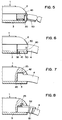
- Figure 5 shows another embodiment for attaching a bracelet made of metal links; the last link, which may be of synthetic or metallic material, has a notch 40 in which is housed a claw 30 arranged as above on an extension of the bottom 3. An intermediate piece 50, also held by the claw 30, is welded to the undersides of the last and the penultimate link of the bracelet to strengthen them.
- Figure 6 the embodiment shown is a juxtaposition of the first and the second embodiment described above; an intermediate piece with two opposite fins 56 sees its first fin used as the claw 30 housed in the notch 40 of the bracelet 4 while its second fin is housed in the opening 32 of the bottom 3, like the projection 41.
- Figure 7 lends itself well to a synthetic strap; the end of the latter has a protrusion 42 directed towards the bottom of the recess 20 which itself has a second recess 25 making it possible to retain the protrusion 42.
- the bottom 3 is flat having no claw or retaining opening.
- FIG. 8 The embodiment of FIG. 8 is derived from the previous one and makes it possible to adapt it to a leather strap: a retaining piece 52 comprises a small fin coming to be housed in the second recess 25 and an elongated body, slightly bent , attached to the bracelet 4 by any suitable means, for example using a rivet 51. Since part of this retaining piece 52 is visible above the bracelet, said part is designed to be of aesthetic presentation.
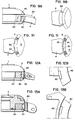
- FIGS. 9A and 9B show an embodiment derived from the first embodiment; or the claws 30 completely pass through the bracelet 4 in through notches 40, an aesthetic cover plate 53, held by one of its ends curved in the recess 20, hides the ends of the claw (s) 30.
- the cover plate 53 we see an example of the aesthetic appearance that the cover plate 53 can have on the bracelet 4.
- Figures 10 and 11 show two different embodiments, in which the claws 30 for Figure 10 or the opening 32 for Figure 11 are not made on a part in extension of the bottom 3, but on a bar 33 fixed by two screws at the bottom of the middle part 2.
- the bottom 3 of the case is absolutely circular and can be screwed by an external thread in the housing to be fixed to the middle part or to the container by known sealing and fixing means.
- FIGS. 12A and 12B there is a intermediate fixing part 43, a first part of which is housed in the recess 20, being held by claws 30 in the notches 40 arranged in this first part, while the second part is in the form of a hinge, making it possible to fix n ' any bracelet intended to be attached using this known technique.
- the fixing piece 44 visible in FIGS. 13A and 13B is similar to the previous one, except that its second part comprises two horns making it possible to fix any bracelet intended to be fixed according to this known technique.
- intermediate parts 43 and 44 described above as comprising notches 40 for receiving the claws 30, can just as easily be arranged with protuberances coming to be housed in openings in the bottom.
- hinge fastening system is shown with a single hinge, but any hinge fastening system, possibly comprising several hinges can be envisaged.
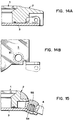
- a variant of these latter embodiments consists in placing these fastening elements directly on the bottom 3 of the box, as shown in FIGS. 14A and 14B for an execution with ears, obtained by folding down two extensions of the bottom 3.
- FIG. 15 Yet another embodiment is shown in FIG. 15, this embodiment making it possible in particular to change the strap without it being necessary to unscrew the case back 3.
- an extension of the case 3 is slightly bent in order to accommodate the curvature wrist; this extension is pierced with one or more holes in which one or more screws 54, cooperating with one or more threaded plugs 55, hold the strap 4, drilled so as to receive said threaded plugs. The upper ends of these being visible, their appearance will be treated.
- FIGS 16A and 16B show yet another embodiment of the bottom 3, adapted to the embodiment of the fixing device shown in Figures 1A and 1B.
- the bottom 3 here consists of three parts, a first central part 34, of generally circular shape and having two bearing surfaces 34A, arranged symmetrically and against which two support flanges 35 are supported, each of them comprising a bearing surface of a shape complementary to that of the corresponding bearing surface 34A and fixed to the middle part 2 by means of the screws 36 engaged in the holes 31 arranged in the flanges 35.
- This particular embodiment of the base 3 described here for the first embodiment of the fixing device, can obviously be adapted and used for all the other described embodiments of said device for fixing a bracelet to a case.
- the invention is particularly well suited to metal cases, specifically made of stainless steel; the additional machining operation to arrange the recess (s) to receive the end of the bracelet strand can easily be carried out by plunge milling, using automatic machines with multiple stations and with conventional linear or circular cycles.
- the case backs, also metallic, respectively made of stainless steel, can easily be obtained in a single machining operation by stamping possibly followed by folding for making the claws, and this, whatever the shape of execution retained.
- the fixing system according to the invention mainly for aesthetic reasons, nothing prevents the fixing system according to the invention from being used for cases and / or bottoms made of other materials, such as simple or precious metals, composites, ceramics, sintered metals or synthetic materials, in this case the advantage of the invention lies in the fact that it is possible to use molds or dies which are simple and easy to execute.
- the case and the device for attaching a strap to a watch case according to the invention perfectly meet the requirements set, that is to greatly facilitate the machining and finishing of the watch case since the latter is entirely symmetrical, without any element projecting, which allows it to be mounted on a machining or automatic finishing machine, which results in a significantly reduced manufacturing cost.
- some of the embodiments described make it possible to renew the aesthetics of the attachment of the bracelet to the case, which is an additional advantage of the invention.
- the fixing of the bracelet is absolutely secure, is not subject to wear and allows easy changing of the bracelet and even, passing from one embodiment to another, while keeping the same case, to change the type of bracelet, going from a synthetic bracelet to a leather bracelet or a metallic bracelet or vice versa, and even to use bracelets of classic design.
Abstract
Description
La présente invention concerne un boîtier de montre et plus particulièrement un dispositif de fixation d'un bracelet audit boîtier de montre.The present invention relates to a watch case and more particularly to a device for fixing a bracelet to said watch case.
Le dispositif de fixation d'un bracelet à un boîtier de montre est en général assez compliqué, tant par le nombre de pièces différentes qu'il requiert que par la complexité de ces différentes pièces ainsi que leur difficulté d'usinage; en particulier les extrémités de chaque brin de bracelet ainsi que le boîtier de la montre doivent être spécialement formés et usinés pour pouvoir s'assembler. De plus le montage de ces divers éléments est aussi assez long et par conséquent coûteux.The device for attaching a bracelet to a watch case is generally quite complicated, as much by the number of different parts it requires as by the complexity of these different parts as well as their difficulty in machining; in particular the ends of each bracelet strand as well as the watch case must be specially formed and machined to be able to assemble. In addition the assembly of these various elements is also quite long and therefore expensive.
En particulier, le système de fixation habituel courant est basé sur la présence de deux cornes ou autres éléments en saillie pour chaque brin de bracelet à fixer au boîtier, une barrette transversale, dont les extrémités sont fixées à chacune de ces cornes, venant se loger dans un trou de halage transversal aménagé à l'extrémité du brin de bracelet. Ces cornes ou autres éléments, venant en saillie sur le pourtour de la carrure, empêchent l'automatisation de nombreuses opérations d'usinage ou de finition, condamnant ainsi à un travail manuel important et coûteux. Les boîtiers classiques munis de cornes ou autres éléments sont généralement frappés à chaud; pour ceci, il est nécessaire de procéder à plusieurs frappes afin de permettre un écoulement suffisant de la matière, des recuits intermédiaires étant nécessaires. De plus, il est impossible de procéder à une frappe en matrice fermée ce qui permettrait d'éviter des surplus de matière, qui devront alors être éliminés par des opérations ultérieures de découpage, de fraisage ou de tournage, opérations supplémentaires longues et coûteuses. Enfin, lors de la finition du boîtier, la présence des même cornes ou autres éléments empêche de recourir à des moyens automatiques de lapidage, facettage, diamantage ou de polissage, une partie de ces opérations devant se faire manuellement afin d'éviter d'endommager les cornes ou autres éléments en saillie.In particular, the current usual fixing system is based on the presence of two horns or other projecting elements for each strand of bracelet to be fixed to the case, a transverse bar, the ends of which are fixed to each of these horns, coming to be housed in a transverse haulage hole at the end of the bracelet strand. These horns or other elements, protruding around the circumference of the middle, prevent the automation of many machining or finishing operations, thus conducive to significant and costly manual work. Conventional cases provided with horns or other elements are generally hot stamped; for this, it is necessary to make several strikes to allow sufficient flow of the material, intermediate annealing being necessary. In addition, it is impossible to strike in a closed matrix which would avoid excess material, which will then have to be removed by subsequent operations of cutting, milling or turning, long and costly additional operations. Finally, during the finishing of the case, the presence of the same horns or other elements prevents the use of automatic stoning, faceting, diamond or polishing means, part of these operations having to be done manually to avoid damaging horns or other protruding elements.
Ces différents facteurs, propres en particulier aux boîtiers métalliques, renchérissent considérablement le coût desdits boîtiers.These various factors, specific in particular to metal housings, considerably increase the cost of said housings.
Il en est de même des bracelets qui doivent être spécialement façonnés afin de comprendre le trou de halage transversal chargé de recevoir la barrette de fixation aux cornes.It is the same for bracelets which must be specially shaped in order to understand the transverse hauling hole responsible for receiving the bar for fixing to the horns.
Divers documents publiés montrent que l'industrie horlogère recherche activement une solution satisfaisante au problème évoqué; la plupart d'entre eux butent sur la nécessité de reporter la complexité de l'usinage soit sur la carrure, soit sur le fond du boîtier. En particulier, les documents US-A-4.034.552, DE-U-8.136.009, EP-A-264.875, EP-A-52.316, CH-A-647.123, CH-A-355.095, CH-A-347.490, US-A-2.225.474, JP-A-57.86.776, et DE-A-3.309.094 décrivent des systèmes de fixation impliquant des carrures et/ou des fonds de boîtier difficiles à usiner. Les fonds de boîtier décrits dans la plupart des documents ci-dessus ne peuvent pas être usinés en un seul passage et nécessitent tous des reprises d'usinage, ce qui en augmente notablement le coût. D'autre part, le système décrit dans le document DE-A-2.530.154, n'est pas davantage satisfaisant; l'usinage de la boîte est très coûteux, de par le grand nombre d'opérations d'usinage et de reprise nécessaires. De plus, l'aménagement des évidements nécessaires à la tenue des extrémités des brins de bracelets nécessite des opérations de fraisage en bout, opérations qui sont toujours délicates. Enfin, les brins de bracelet ne sont pas maintenus par le fond du boîtier, mais sont collés dans les évidements, ce qui rend le système indémontable.Various published documents show that the watch industry is actively seeking a satisfactory solution to the problem mentioned; most of them come up against the need to transfer the complexity of the machining either to the middle or to the bottom of the case. In particular, documents US-A-4,034,552, DE-U-8,136.009, EP-A-264.875, EP-A-52.316, CH-A-647.123, CH-A-355.095, CH-A-347.490 , US-A-2.225.474, JP-A-57.86.776, and DE-A-3.309.094 describe fastening systems involving shoulders and / or case backs which are difficult to machine. The case backs described in most of the above documents cannot be machined in a single pass and all require reworking, which significantly increases the cost. On the other hand, the system described in document DE-A-2,530,154 is not more satisfactory; machining the box is very expensive, due to the large number of machining and rework operations required. In addition, the arrangement of the recesses necessary to hold the ends of the strands of bracelets require end milling operations, operations which are always delicate. Finally, the bracelet strands are not held by the bottom of the case, but are glued into the recesses, which makes the system non-removable.
Un premier but de l'invention est donc de proposer un boîtier de montre et un dispositif de fixation d'un bracelet de conception très simple, nécessitant peu de pièces, et dont la fabrication desdites pièces est facile, pouvant être entièrement automatisée par des moyens classiques et ne nécessitant pas de reprise pour des opérations ultérieures de tournage ou de fraisage. Le boîtier ou la carrure ne comporte ni cornes, ni aucun autre élément en saillie, ce qui permet d'avoir un boîtier entièrement symétrique. Le fond de boîtier peut être travaillé en un seul passage à partir d'une bande de tôle alors que les brins du bracelet sont eux aussi très simples de fabrication. Ces divers facteurs doivent réduire considérablement le prix de revient de la boîte complète.A first object of the invention is therefore to propose a watch case and a device for fixing a bracelet of very simple design, requiring few parts, and the manufacture of which is easy, which can be entirely automated by means conventional and not requiring rework for subsequent turning or milling operations. The case or middle part has neither horns, nor any other projecting element, which makes it possible to have a completely symmetrical case. The case back can be worked in a single pass from a sheet metal strip while the strands of the bracelet are also very simple to manufacture. These various factors must considerably reduce the cost price of the complete box.
Un deuxième but de l'invention est que ledit dispositif soit démontable et que l'un ou l'autre de ses composants, le bracelet par exemple, soit échangeable en cas d'usure ou de changement de mode par exemple.A second object of the invention is that said device is removable and that one or other of its components, the bracelet for example, is exchangeable in case of wear or change of mode for example.
Un troisième but de l'invention est de proposer un système de haute valeur esthétique dont certains éléments peuvent être facilement transformés ou ajoutés, selon la mode ou le désir du porteur de la montre.A third object of the invention is to propose a system of high aesthetic value, certain elements of which can be easily transformed or added, according to the fashion or the desire of the wearer of the watch.
Afin d'atteindre les buts fixés, tout en évitant les inconvénients des dispositifs de l'art antérieur, le boîtier et le dispositif de fixation selon l'invention comportent les caractères mentionnés dans les parties caractérisantes des revendications.In order to achieve the goals set, while avoiding the drawbacks of the devices of the prior art, the housing and the fixing device according to the invention include the characters mentioned in the characterizing parts of the claims.
Le boîtier de montre et le dispositif de fixation d'un bracelet selon l'invention, comportant différentes formes d'exécution, sont particulièrement compréhensibles à partir du dessin d'accompagnement avec les figures où:
- la figure 1 représente une première forme d'exécution du système de fixation selon l'invention, la figure 1A étant une coupe, la figure 1B une vue de dessous d'une portion du fond du boîtier, et la figure 1C une vue de dessous d'une portion du boîtier,
- la figure 2 représente une deuxième forme d'exécution du système de fixation selon l'invention, la figure 2A étant une coupe alors que la figure 2B est une vue de dessous d'une portion du fond du boîtier,
- les figures 3 à 8 représentent encore d'autres formes d'exécution de l'invention vue en coupe,
- la figure 9 représente encore une autre forme d'exécution de l'invention, la figure 9A étant une coupe alors que la figure 9B en est une vue par dessus,
- les figures 10 et 11 représentent encore d'autres formes d'exécution de l'invention vues par dessous,
- la figure 12 représente encore une autre forme d'exécution de l'invention, la figure 12A étant une coupe alors que la figure 12B est une vue par dessus d'une pièce constitutive,
- la figure 13 représente encore une autre forme d'exécution de l'invention, la figure 13A étant une coupe alors que la figure 13B est une vue par dessus d'une pièce constitutive,
- la figure 14 représente encore une autre forme d'exécution de l'invention, la figure 14A étant une coupe alors que la figure 14B est une vue par dessous d'une portion du fond du boîtier,
- la figure 15 représente encore une autre forme d'exécution de l'invention, vue en coupe, et
- la figure 16 représente une autre forme d'exécution du fond de boîtier, adaptée à la première forme d'exécution de l'invention, la figure 16A étant une coupe et la figure 16B une vue par dessous d'une portion du fond.
- FIG. 1 represents a first embodiment of the fixing system according to the invention, FIG. 1A being a section, FIG. 1B a view from below of a portion of the bottom of the housing, and FIG. 1C a view from below a portion of the housing,
- FIG. 2 represents a second embodiment of the fastening system according to the invention, FIG. 2A being a section while FIG. 2B is a view from below of a portion of the bottom of the housing,
- FIGS. 3 to 8 show still other embodiments of the invention seen in section,
- FIG. 9 represents yet another embodiment of the invention, FIG. 9A being a section while FIG. 9B is a view from above,
- FIGS. 10 and 11 show still other embodiments of the invention seen from below,
- FIG. 12 represents yet another embodiment of the invention, FIG. 12A being a section while FIG. 12B is a view from above of a component part,
- FIG. 13 represents yet another embodiment of the invention, FIG. 13A being a section while FIG. 13B is a view from above of a component part,
- FIG. 14 represents yet another embodiment of the invention, FIG. 14A being a section while FIG. 14B is a view from below of a portion of the bottom of the housing,
- FIG. 15 shows yet another embodiment of the invention, seen in section, and
- FIG. 16 represents another embodiment of the bottom of the housing, adapted to the first embodiment of the invention, FIG. 16A being a section and FIG. 16B a view from below of a portion of the bottom.
La forme d'exécution représentée aux figures 1A, 1B et 1C se prête particulièrement bien à la fixation d'un bracelet de cuir, de matière synthétique ou métallique; on a tout d'abord un boîtier 1 comprenant une carrure 2, maintenant un mouvement d'horlogerie 10, pouvant être de n'importe quel type connu de la technique, ainsi qu'un verre 11. Un fond de boîtier 3 ferme le boîtier 1 par dessous, l'étanchéité étant assurée par un joint 12 disposé dans une rainure faite dans le fond de la carrure 2. Un bracelet 4 est fixé audit boîtier. Sur la figure 1A, on voit que la carrure 2 comprend un évidement 20, destiné à recevoir l'extrémité du brin de bracelet 4, aménagé sur une portion de couronne du fond de la carrure. La forme générale de cet évidement 20, taillé comme un secteur de couronne, est visible sur la figure 1C. L'évidement 20 peut aussi être taillé avec des faces parallèles. Il est bien entendu que la carrure comprend aussi un second évidemment, disposé symétriquement de l'autre côté. On constate donc que la carrure, contrairement aux autres carrures de l'art antérieur, ne comporte aucun élément en saillie empêchant ou rendant difficile son usinage complet par des moyens automatiques, et en particulier une frappe à froid en matrice fermée, les entrées pour le bracelet et les trous de fixation du fond étant exécutés sur machine linéaire ou circulaire à têtes multi-broches. L'extrémité du bracelet 4 a une forme adaptée pour venir se loger dans l'évidement 20 et y occuper toute la place. Un peu en retrait de cette extrémité du brin de bracelet, celui-ci est partiellement creusé par une ou plusieurs encoches 40 dans lesquelles viennent se loger une ou plusieurs griffes 30, constituées d'un ou plusieurs prolongements du fond 3, et qui sont repliées vers le haut. Le fond de boîtier 3, qui est d'épaisseur uniforme, peut donc être obtenu très facilement à partir d'une bande de tôle par exemple, qui peut être découpée et dont les griffes 30 peuvent être repliées en une seule opération d'usinage automatique, par exemple par une machine linéaire à postes multiples. Pour le montage du bracelet 4, il suffit d'introduire ses extrémités par dessous dans les évidements 20 prévus de chaque côté de la montre, les encoches 40 étant dirigées vers le fond de la montre, puis de présenter le fond 3 avec les griffes 30 qui viennent s'engager dans les encoches 40 et de visser le fond 3 au boîtier 1 au-moyen de vis s'engageant dans des trous 31 du fond puis dans des trous taraudés aménagés dans le boîtier ou la carrure. Vu la bonne tenue du bracelet entre les griffes 30 et le fond de l'évidement 20 contre lequel il s'appuie, il n'est pas nécessaire de renforcer les encoches 40 du bracelet.The embodiment shown in Figures 1A, 1B and 1C lends itself particularly well to the attachment of a leather strap, synthetic or metallic; first of all there is a
Les figures 2A et 2B représentent une autre forme d'exécution qui se prête très bien à la fixation d'un bracelet de matière synthétique; la carrure 2 comprend un évidement 20 identique à celui décrit pour la forme d'exécution précédente, alors que le fond 3 ne comporte plus de griffes, mais une ou plusieurs ouvertures transversales 32, dans laquelle ou lesquelles viendront se loger une ou plusieurs excroissances 41 aménagées à l'extrémité du brin du bracelet 4. Il est évident que dans cette forme d'exécution, le fond de boîtier 3 peut aussi être obtenu à partir d'une bande de tôle par des moyens automatiques de production. Cette ou ces excroissances 41 sont directement obtenues lors du moulage du bracelet 4. Comme précédemment, après introduction des extrémités du bracelet 4 dans les évidements 20, les excroissances 41 étant dirigées vers le fond du boîtier, il suffit de poser le fond 3 avec ses ouvertures 32 entourant les excroissance 41 et de le visser au boîtier 1. Une autre forme d'exécution de la carrure 2 est aussi représentée à la figure 2A; au-lieu d'être formée en une seule pièce comme précédemment, elle est formée ici de trois pièces, la carrure proprement dite 22, une cartouche ou container 21 du mouvement et une bague de garniture 23. Ces trois pièces peuvent être métalliques, en céramique ou en matériau synthétique, les trois pièces étant du même ou de matériaux différents; elles sont assemblées et fixées les unes sur les autres et sur le boîtier par des moyens connus, par chassage, sertissage ou collage. En particulier la bague de garniture 23 peut être fixe ou tournante, afin de déplacer un repère ou une graduation mobile, ou alors elle peut constituer un décor pouvant être interchangeable.FIGS. 2A and 2B represent another embodiment which lends itself very well to the attachment of a bracelet of synthetic material; the
L'intérêt de prévoir la carrure en trois pièces distinctes comprenant en particulier une cartouche ou container contenant le mouvement, est que l'injection d'un tel container en matière synthétique est très facile, et ne nécessite aucun usinage complémentaire, ce container jouant aussi le rôle de joint d'étanchéité pour le verre.The advantage of providing the middle part in three separate parts comprising in particular a cartridge or container containing the movement, is that the injection of such a plastic container is very easy, and does not require any additional machining, this container also playing the role of gasket for glass.
Une autre forme d'exécution est représentée à la figure 3, une pièce intermédiaire 50 en forme de L, dont le grand côté est légèrement recourbé et est percé d'un trou, a son petit côté engagé dans l'ouverture 32 du fond 3, alors que le bracelet 4 est fixé à ladite pièce en forme de L par un rivet 51 ou par n'importe quel autre moyen convenable qui le maintient au fond de l'évidement aménagé dans la carrure. Une autre forme d'exécution de la carrure 2 est aussi représentée sur cette figure, ladite carrure étant ici formée de deux pièces, la carrure proprement dite 24 faisant aussi office de cartouche ou container ainsi que de la bague de garniture 23. Comme précédemment, ces pièces peuvent être métalliques ou en matériau synthétique, du même matériau ou de matériaux différents, la bague de garniture 23 pouvant être fixe, tournante ou interchangeable.Another embodiment is shown in FIG. 3, an L-shaped
La forme d'exécution de la figure 4 se prête très bien à la fixation d'un bracelet 4 constitué de maillons métalliques, dont le dernier maillon occupe l'évidement 20 aménagé dans la carrure 2. Comme dans la forme d'exécution précédente, une pièce intermédiaire 50 en forme de L a son grand côté soudé sur la face inférieure du dernier et de l'avant-dernier maillon, alors que son petit côté s'engage dans l'ouverture 32 du fond 3.The embodiment of FIG. 4 lends itself very well to the attachment of a
La figure 5 représente une autre forme d'exécution permettant de fixer un bracelet constitué de maillons métalliques; le dernier maillon, pouvant être en matériau synthétique ou métallique, comporte une encoche 40 dans laquelle vient se loger une griffe 30 aménagée comme plus haut sur un prolongement du fond 3. Une pièce intermédiaire 50, aussi maintenue par la griffe 30, est soudée sur les faces inférieures du dernier et de l'avant dernier maillon du bracelet afin de les renforcer.Figure 5 shows another embodiment for attaching a bracelet made of metal links; the last link, which may be of synthetic or metallic material, has a
A la figure 6, la forme d'exécution représentée est une juxtaposition de la première et de la deuxième forme d'exécution décrites plus haut; une pièce intermédiaire à deux ailettes opposées 56 voit sa première ailette utilisée comme la griffe 30 logée dans l'encoche 40 du bracelet 4 alors que sa seconde ailette est logée dans l'ouverture 32 du fond 3, comme l'excroissance 41.In Figure 6, the embodiment shown is a juxtaposition of the first and the second embodiment described above; an intermediate piece with two opposite fins 56 sees its first fin used as the
La forme d'exécution de la figure 7 se prête bien à un bracelet en matière synthétique; l'extrémité de celui-ci comporte une excroissance 42 dirigée vers le fond de l'évidement 20 qui comporte lui un second évidement 25 permettant de retenir l'excroissance 42. Dans cette forme d'exécution, le fond 3 est plat ne comportant aucune griffe ou ouverture de retenue.The embodiment of Figure 7 lends itself well to a synthetic strap; the end of the latter has a
La forme d'exécution de la figure 8 est dérivée de la précédente et permet de l'adapter à un bracelet de cuir: une pièce de retenue 52 comporte une petite ailette venant se loger dans le second évidement 25 et un corps allongé, légèrement coudé, fixé au bracelet 4 par n'importe quel moyen convenable, par exemple à l'aide d'un rivet 51. Vu qu'une partie de cette pièce de retenue 52 est visible par dessus le bracelet, ladite partie est conçue pour être de présentation esthétique.The embodiment of FIG. 8 is derived from the previous one and makes it possible to adapt it to a leather strap: a retaining
Les figures 9A et 9B montrent une forme d'exécution dérivée de la première forme d'exécution; la ou les griffes 30 traversent complètement le bracelet 4 dans des encoches traversantes 40, une plaque de recouvrement esthétique 53, maintenue par une de ses extrémités recourbée dans l'évidement 20, vient cacher les extrémités de la ou des griffes 30. A la figure 9B, on voit un exemple de l'aspect esthétique que peut avoir la plaque de recouvrement 53 sur le bracelet 4.FIGS. 9A and 9B show an embodiment derived from the first embodiment; or the
Les figures 10 et 11 montrent deux formes d'exécution différentes, dans lesquelles les griffes 30 pour la figure 10 ou l'ouverture 32 pour la figure 11 ne sont pas faites sur une partie en prolongement du fond 3, mais sur une barrette 33 fixée par deux vis au fond de la carrure 2. De cette manière, le fond 3 du boîtier est absolument circulaire et peut être vissé par un filetage extérieur dans le boîtier pour être fixé à la carrure ou au container par des moyens d'étanchéité et de fixation connus.Figures 10 and 11 show two different embodiments, in which the
Au cas où pour des raisons d'exigences commerciales ou de mode, on désire retrouver un système de fixation habituel par cornes ou gonds, on peut adopter les formes d'exécution des figures 12 et 13. Aux figures 12A et 12B, on a une pièce intermédiaire de fixation 43 dont une première partie vient se loger dans l'évidement 20, étant maintenue par des griffes 30 dans les encoches 40 aménagées dans cette première partie, alors que la seconde partie est en forme de gond, permettant de fixer n'importe quel bracelet prévu pour être fixé selon cette technique connue. La pièce de fixation 44, visible aux figures 13A et 13B est semblable à la précédente, si ce n'est que sa seconde partie comprend deux cornes permettant de fixer n'importe quel bracelet prévu pour être fixé selon cette technique connue.If for reasons of commercial or fashion requirements, we wish to find a usual fixing system by horns or hinges, we can adopt the embodiments of FIGS. 12 and 13. In FIGS. 12A and 12B, there is a intermediate fixing
Il est bien entendu que les pièces intermédiaires 43 et 44 décrites plus haut comme comprenant des encoches 40 pour recevoir les griffes 30, peuvent tout aussi bien être aménagées avec des excroissances venant se loger dans des ouvertures du fond. De même, le système de fixation à gond est représenté avec une seul gond, mais n'importe quel système de fixation à gond, comprenant éventuellement plusieurs gonds peut être envisagé.It is understood that the
Une variante de ces dernières formes d'exécution consiste à disposer ces éléments d'attache directement sur le fond 3 de la boîte, comme représenté aux figures 14A et 14B pour une exécution avec des oreilles, obtenues par rabattement de deux prolongements du fond 3.A variant of these latter embodiments consists in placing these fastening elements directly on the
Encore une autre forme d'exécution est représentée à la figure 15, cette forme d'exécution permettant en particulier de changer de bracelet sans qu'il soit nécessaire de dévisser le fond de boîtier 3. Pour ceci, un prolongement du fond 3 est légèrement coudé afin de s'accommoder de la courbure du poignet; ce prolongement est percé d'un ou plusieurs trous dans lesquels une ou plusieurs vis 54, coopérant avec un ou plusieurs bouchons taraudés 55, maintiennent le bracelet 4, percé afin de recevoir lesdits bouchons taraudés. Les extrémités supérieures de ceux-ci étant visibles, leur aspect en sera soigné.Yet another embodiment is shown in FIG. 15, this embodiment making it possible in particular to change the strap without it being necessary to unscrew the case back 3. For this, an extension of the
Les figures 16A et 16B représentent encore une autre forme d'exécution du fond 3, adapté à la forme d'exécution du dispositif de fixation représenté aux figures 1A et 1B. Le fond 3 est ici constitué de trois parties, une première partie centrale 34, de forme généralement circulaire et comportant deux portées d'appui 34A, disposées symétriquement et contre lesquelles viennent s'appuyer deux brides d'appui 35, chacune d'entre elles comportant une portée d'appui de forme complémentaire à celle de la portée d'appui 34A correspondante et fixée à la carrure 2 au moyen des vis 36 engagées dans les trous 31 aménagés dans les brides 35. Cette forme d'exécution particulière du fond 3, décrite ici pour la première forme d'exécution du dispositif de fixation, peut évidemment être adaptée et utilisée pour toutes les autres formes d'exécution décrites dudit dispositif de fixation d'un bracelet à un boîtier.Figures 16A and 16B show yet another embodiment of the
Les différentes formes d'exécution du boîtier et du dispositif de fixation d'un bracelet à un boîtier de montre ont été décrites adaptées à un boîtier de montre circulaire; il est bien entendu que l'invention s'adapte aussi parfaitement bien à des boîtiers ovales ou alors carrés ou rectangulaires; plus généralement, le système selon l'invention peut être prévu pour un boîtier de montre de n'importe quelle forme. Dans certains cas d'application où la montre n'est pas mise autour du poignet mais est suspendue, il est évident que ce dispositif s'applique tout aussi bien en ne prévoyant qu'un seul dispositif de fixation reliant le boîtier au brin de suspension.The different embodiments of the case and of the device for attaching a bracelet to a watch case have been described adapted to a circular watch case; it is understood that the invention also adapts perfectly well to oval or square or rectangular boxes; more generally, the system according to the invention can be intended for a watch case of any shape. In certain application cases where the watch is not put around the wrist but is suspended, it is obvious that this device applies just as well by providing only one fixing device connecting the housing to the suspension strand .
Pour les raisons de simplification des procédés de fabrication ou de finition mentionnées plus haut, l'invention est particulièrement bien adaptée à des boîtiers métalliques, spécifiquement en acier inoxydable; l'opération d'usinage supplémentaire pour aménager le ou les évidements devant recevoir l'extrémité du brin de bracelet peut facilement être exécutée par fraisage en plongée, en utilisant des machines automatiques à postes multiples et à cycles linéaires ou circulaires classiques. Les fonds de boîtier, eux aussi métalliques, respectivement en acier inoxydable, peuvent facilement être obtenus en une seule opération d'usinage par un étampage suivi éventuellement d'un pliage pour la confection des griffes, et ceci, quelle que soit la forme d'exécution retenue.For reasons of simplification of the manufacturing or finishing processes mentioned above, the invention is particularly well suited to metal cases, specifically made of stainless steel; the additional machining operation to arrange the recess (s) to receive the end of the bracelet strand can easily be carried out by plunge milling, using automatic machines with multiple stations and with conventional linear or circular cycles. The case backs, also metallic, respectively made of stainless steel, can easily be obtained in a single machining operation by stamping possibly followed by folding for making the claws, and this, whatever the shape of execution retained.
Néanmoins, principalement pour des raisons esthétiques, rien n'empêche d'utiliser le système de fixation selon l'invention pour des boîtiers et/ou des fonds en d'autres matériaux, comme par exemple des métaux simples ou précieux, des composites, des céramiques, des métaux frittés ou des matières synthétiques, dans ce cas l'avantage de l'invention réside dans le fait que l'on peut utiliser des moules ou des matrices simples et faciles à exécuter.However, mainly for aesthetic reasons, nothing prevents the fixing system according to the invention from being used for cases and / or bottoms made of other materials, such as simple or precious metals, composites, ceramics, sintered metals or synthetic materials, in this case the advantage of the invention lies in the fact that it is possible to use molds or dies which are simple and easy to execute.
Bien que plusieurs formes d'exécution du boîtier et du dispositif de fixation selon l'invention ont été décrites, il est évident que d'autres formes d'exécution, dérivant des précédentes, sont possibles; par conséquent ces autres formes d'exécution, ainsi que celles résultant de légères modifications des formes d'exécution décrites, restent protégées par la présente demande.Although several embodiments of the housing and of the fixing device according to the invention have been described, it is obvious that other embodiments, deriving from the preceding ones, are possible; therefore these other embodiments, as well as those resulting from slight modifications of the described embodiments, remain protected by the present request.
Le boîtier et le dispositif de fixation d'un bracelet à un boîtier de montre selon l'invention répondent parfaitement aux exigences fixées, soit de faciliter grandement l'usinage et la finition du boîtier de montre puisque ce dernier est entièrement symétrique, sans aucun élément faisant saillie, ce qui permet de le monter sur une machine d'usinage ou de finition automatique, d'où il en résulte un coût de fabrication nettement diminué. De plus, certaines des formes d'exécution décrites permettent de renouveler l'esthétique de la fixation du bracelet au boîtier, ce qui est un avantage supplémentaire de l'invention. D'autre part, la fixation du bracelet est absolument sûre, n'est pas soumise à usure et permet facilement de changer le bracelet et même, en passant d'une forme d'exécution à une autre, tout en conservant le même boîtier, de changer de type de bracelet, passant d'un bracelet en matière synthétique à un bracelet en cuir ou à un bracelet métallique ou vice versa, et même d'utiliser des bracelets de conception classique.The case and the device for attaching a strap to a watch case according to the invention perfectly meet the requirements set, that is to greatly facilitate the machining and finishing of the watch case since the latter is entirely symmetrical, without any element projecting, which allows it to be mounted on a machining or automatic finishing machine, which results in a significantly reduced manufacturing cost. In addition, some of the embodiments described make it possible to renew the aesthetics of the attachment of the bracelet to the case, which is an additional advantage of the invention. On the other hand, the fixing of the bracelet is absolutely secure, is not subject to wear and allows easy changing of the bracelet and even, passing from one embodiment to another, while keeping the same case, to change the type of bracelet, going from a synthetic bracelet to a leather bracelet or a metallic bracelet or vice versa, and even to use bracelets of classic design.
Claims (16)
Applications Claiming Priority (2)
| Application Number | Priority Date | Filing Date | Title |
|---|---|---|---|
| CH2346/90 | 1990-07-13 | ||
| CH234690 | 1990-07-13 |
Publications (1)
| Publication Number | Publication Date |
|---|---|
| EP0466655A1 true EP0466655A1 (en) | 1992-01-15 |
Family
ID=4231652
Family Applications (1)
| Application Number | Title | Priority Date | Filing Date |
|---|---|---|---|
| EP91810553A Withdrawn EP0466655A1 (en) | 1990-07-13 | 1991-07-11 | Watch case and device for fastening a bracelet |
Country Status (3)
| Country | Link |
|---|---|
| US (1) | US5341552A (en) |
| EP (1) | EP0466655A1 (en) |
| JP (1) | JPH0666960A (en) |
Cited By (6)
| Publication number | Priority date | Publication date | Assignee | Title |
|---|---|---|---|---|
| EP1012676A1 (en) * | 1996-11-13 | 2000-06-28 | Bonneville Watches, a division of Bonneville Worldwide, Inc. | Modular wristwatch assembly and case assembly for same |
| EP3231313A1 (en) * | 2016-04-15 | 2017-10-18 | J.R. International GmbH | Casing for wrist watches |
| CN109799691A (en) * | 2019-03-31 | 2019-05-24 | 翁琦 | It is a kind of to splice the wrist-watch for realizing watchband replacement based on track |
| EP3798742A1 (en) | 2019-09-24 | 2021-03-31 | ETA SA Manufacture Horlogère Suisse | Device for connecting case body and lugs for a watch |
| WO2021058213A1 (en) | 2019-09-24 | 2021-04-01 | Eta Sa Manufacture Horlogère Suisse | Device for horn/middle connection for a watch |
| FR3104006A1 (en) * | 2019-12-10 | 2021-06-11 | Red Earl | Watch comprising at least one case, one bracelet and means for removable connection of said bracelet to said case |
Families Citing this family (10)
| Publication number | Priority date | Publication date | Assignee | Title |
|---|---|---|---|---|
| JP4571292B2 (en) * | 2000-09-27 | 2010-10-27 | シチズンホールディングス株式会社 | Connecting structure of watch case and band |
| EP1269879B1 (en) * | 2001-06-27 | 2006-08-02 | The Swatch Group Management Services AG | Device for fixing bracelet strap to wrist watch |
| TW517181B (en) * | 2001-06-27 | 2003-01-11 | Swatch Group Man Serv Ag | Device for attaching wristband strands to a case |
| FI120957B (en) * | 2005-02-17 | 2010-05-31 | Suunto Oy | the fixing mechanism |
| US7300201B2 (en) * | 2005-03-01 | 2007-11-27 | Skagen Designs Ltd. | Wristwatch and coupling assembly for releasably joining a wristwatch case to a wristband |
| US7654732B2 (en) * | 2007-08-31 | 2010-02-02 | Nike, Inc. | Timepiece incorporating wristband contact elements |
| US8007165B1 (en) * | 2010-02-19 | 2011-08-30 | Invicta Watch Company Of America, Inc. | Coupling assembly for a wristwatch |
| CH708815B1 (en) * | 2013-11-06 | 2017-12-29 | The Swatch Group Man Services Ag | Cladding element for a middle part of a wristwatch. |
| RU2582885C1 (en) * | 2014-09-30 | 2016-04-27 | Общество С Ограниченной Ответственностью "Часовой Завод Ника" | Clock with decorative case and replaceable decorative framework on strap, clock housing with replaceable decorative frame, rear cover for clock with replaceable decorative frame and replaceable decorative frame for clock with decorative housing |
| RU172161U1 (en) * | 2017-01-20 | 2017-06-29 | Общество С Ограниченной Ответственностью "Часовой Завод Ника" | CUTTING WATCHES |
Citations (11)
| Publication number | Priority date | Publication date | Assignee | Title |
|---|---|---|---|---|
| US2225474A (en) * | 1938-07-30 | 1940-12-17 | Waterbury Clock Company | Wrist-watch case |
| CH347490A (en) * | 1959-06-18 | 1960-06-30 | Voumard Bertrand | Device for attaching a flat strap to a watch case |
| CH355094A (en) * | 1959-06-02 | 1961-06-15 | Morf Ernest | Wrist watch box |
| CH355095A (en) * | 1959-06-10 | 1961-06-15 | Sorna Watch Sa | Wristwatch |
| DE2530154A1 (en) * | 1975-07-05 | 1977-02-03 | Hartmut Kuehn | Wrist watch casing - is circular frame having fixing apertures for flible watch bracelet |
| US4034552A (en) * | 1976-04-05 | 1977-07-12 | Charles Davidson | Wrist watch |
| DE8136009U1 (en) * | 1981-12-10 | 1982-03-11 | Richard Pfisterer Gmbh & Co, 7530 Pforzheim | clock |
| EP0052316A1 (en) * | 1980-11-15 | 1982-05-26 | RODI & WIENENBERGER Aktiengesellschaft | Wrist-watch |
| DE3309409A1 (en) * | 1983-03-16 | 1984-09-27 | IWC International Watch Co AG, Schaffhausen | Fastening device |
| EP0264875A1 (en) * | 1986-10-22 | 1988-04-27 | Eta SA Fabriques d'Ebauches | Attachment of a bracelet to a watch case |
| EP0150746B1 (en) * | 1984-01-26 | 1989-10-04 | Montres Rado S.A. | Watch case |
Family Cites Families (13)
| Publication number | Priority date | Publication date | Assignee | Title |
|---|---|---|---|---|
| US1380812A (en) * | 1920-08-13 | 1921-06-07 | Waterbury Clock Co | Clock-dial back and mat |
| US3242664A (en) * | 1961-11-08 | 1966-03-29 | Schlup & Cie S A | Watch case |
| JPS5316362A (en) * | 1976-07-30 | 1978-02-15 | Nippon Kokan Kk <Nkk> | Dry distillation treating method for dust |
| JPS5495359A (en) * | 1978-01-13 | 1979-07-27 | Hitachi Ltd | Method of thin film condenser |
| DE3043263A1 (en) * | 1980-11-15 | 1982-07-01 | Rodi & Wienenberger Ag, 7530 Pforzheim | Watertight wrist-watch - has timing unit pressed by upper part of casing against foam elastic buffer in lower part |
| JPS5786776A (en) * | 1980-11-20 | 1982-05-29 | Citizen Watch Co Ltd | Construction to connect watch band to case of wrist watch |
| JPS5796604A (en) * | 1980-12-08 | 1982-06-16 | Citizen Watch Co Ltd | Attachment structure of case and band of wrist watch |
| GB2123330B (en) * | 1982-05-06 | 1986-05-21 | Citizen Watch Co Ltd | Method of making a watchcase |
| JPS59180484A (en) * | 1983-03-31 | 1984-10-13 | Citizen Watch Co Ltd | Method and construction for soldering wrist watch case |
| JPS59183390A (en) * | 1983-04-01 | 1984-10-18 | Citizen Watch Co Ltd | Manufacture of watch case |
| JPS61104965A (en) * | 1984-10-26 | 1986-05-23 | 洲崎 謙吉 | Protective body for pipe end |
| CH672225B5 (en) * | 1987-12-23 | 1990-05-15 | Ebauchesfabrik Eta Ag | |
| JPH04301586A (en) * | 1991-03-29 | 1992-10-26 | Seiko Instr Inc | Band with case and manufacture thereof |
-
1991
- 1991-07-11 EP EP91810553A patent/EP0466655A1/en not_active Withdrawn
- 1991-07-12 JP JP3198516A patent/JPH0666960A/en not_active Ceased
-
1993
- 1993-03-29 US US08/038,078 patent/US5341552A/en not_active Expired - Fee Related
Patent Citations (11)
| Publication number | Priority date | Publication date | Assignee | Title |
|---|---|---|---|---|
| US2225474A (en) * | 1938-07-30 | 1940-12-17 | Waterbury Clock Company | Wrist-watch case |
| CH355094A (en) * | 1959-06-02 | 1961-06-15 | Morf Ernest | Wrist watch box |
| CH355095A (en) * | 1959-06-10 | 1961-06-15 | Sorna Watch Sa | Wristwatch |
| CH347490A (en) * | 1959-06-18 | 1960-06-30 | Voumard Bertrand | Device for attaching a flat strap to a watch case |
| DE2530154A1 (en) * | 1975-07-05 | 1977-02-03 | Hartmut Kuehn | Wrist watch casing - is circular frame having fixing apertures for flible watch bracelet |
| US4034552A (en) * | 1976-04-05 | 1977-07-12 | Charles Davidson | Wrist watch |
| EP0052316A1 (en) * | 1980-11-15 | 1982-05-26 | RODI & WIENENBERGER Aktiengesellschaft | Wrist-watch |
| DE8136009U1 (en) * | 1981-12-10 | 1982-03-11 | Richard Pfisterer Gmbh & Co, 7530 Pforzheim | clock |
| DE3309409A1 (en) * | 1983-03-16 | 1984-09-27 | IWC International Watch Co AG, Schaffhausen | Fastening device |
| EP0150746B1 (en) * | 1984-01-26 | 1989-10-04 | Montres Rado S.A. | Watch case |
| EP0264875A1 (en) * | 1986-10-22 | 1988-04-27 | Eta SA Fabriques d'Ebauches | Attachment of a bracelet to a watch case |
Non-Patent Citations (1)
| Title |
|---|
| PATENT ABSTRACTS OF JAPAN vol. 6, no. 168 (P-139)(1046) 2 Septembre 1982 & JP-A-57 086 776 ( CITIZEN TOKEI K.K. ) 29 Mai 1982 * |
Cited By (10)
| Publication number | Priority date | Publication date | Assignee | Title |
|---|---|---|---|---|
| EP1012676A1 (en) * | 1996-11-13 | 2000-06-28 | Bonneville Watches, a division of Bonneville Worldwide, Inc. | Modular wristwatch assembly and case assembly for same |
| EP1012676A4 (en) * | 1996-11-13 | 2000-06-28 | Bonneville Watches A Division | Modular wristwatch assembly and case assembly for same |
| EP3231313A1 (en) * | 2016-04-15 | 2017-10-18 | J.R. International GmbH | Casing for wrist watches |
| CN109799691A (en) * | 2019-03-31 | 2019-05-24 | 翁琦 | It is a kind of to splice the wrist-watch for realizing watchband replacement based on track |
| CN109799691B (en) * | 2019-03-31 | 2021-03-16 | 翁琦 | Watch capable of realizing watchband replacement based on track splicing |
| EP3798742A1 (en) | 2019-09-24 | 2021-03-31 | ETA SA Manufacture Horlogère Suisse | Device for connecting case body and lugs for a watch |
| WO2021058213A1 (en) | 2019-09-24 | 2021-04-01 | Eta Sa Manufacture Horlogère Suisse | Device for horn/middle connection for a watch |
| CN112631110A (en) * | 2019-09-24 | 2021-04-09 | 伊塔瑞士钟表制造股份有限公司 | Middle part/ear connection device for a wristwatch |
| US11517082B2 (en) | 2019-09-24 | 2022-12-06 | Eta Sa Manufacture Horlogere Suisse | Case middle/horn connection device for a watch |
| FR3104006A1 (en) * | 2019-12-10 | 2021-06-11 | Red Earl | Watch comprising at least one case, one bracelet and means for removable connection of said bracelet to said case |
Also Published As
| Publication number | Publication date |
|---|---|
| US5341552A (en) | 1994-08-30 |
| JPH0666960A (en) | 1994-03-11 |
Similar Documents
| Publication | Publication Date | Title |
|---|---|---|
| EP0466655A1 (en) | Watch case and device for fastening a bracelet | |
| EP0264875B1 (en) | Attachment of a bracelet to a watch case | |
| EP0226533A1 (en) | Watch mounted on a clip | |
| FR2579780A1 (en) | ASSEMBLY CONSISTING OF A WATCHBOX ELEMENT AND A BRACELET | |
| EP3680729B1 (en) | Rotatably adjustable back for a clock piece | |
| EP0541001B1 (en) | Watch-case with a removable back cover | |
| CH684861B5 (en) | watchcase to middle recessed. | |
| EP1098233A1 (en) | Metallic case element with protusions made of synthetic material | |
| EP0109601B1 (en) | Water-proof case for a thin watch movement | |
| CH672225B5 (en) | ||
| EP3958069A1 (en) | Watch case provided with a trim component | |
| EP0626625B1 (en) | Watch case made of precious metal | |
| CA1227346A (en) | Wristwatch case with integrated armband | |
| EP1354247B1 (en) | Watch case with watchband | |
| EP1785784A2 (en) | Device for fixing a watch bracelet | |
| EP1189117B1 (en) | Wristwatch with reversible case | |
| EP3432087B1 (en) | Attachment device | |
| WO2015018718A1 (en) | Exterior casing element and a cap made of metallic glass | |
| CH708418B1 (en) | Cladding element for a timepiece comprising a metal glass cap. | |
| CH682290A5 (en) | Wrist watch bracelet - has holder between two sections of bracelet on opposite side to watch, designed to hold second instrument or container | |
| EP1104894A1 (en) | Wrist watch | |
| CH681413B5 (en) | Wristwatch. | |
| CH717762A2 (en) | Watch case provided with a covering element. | |
| CH686472B5 (en) | Watch case likely to receive a choice of two dials of different sizes. | |
| EP0439081A1 (en) | Arrangement for attaching the strands of a bracelet to a watch case |
Legal Events
| Date | Code | Title | Description |
|---|---|---|---|
| PUAI | Public reference made under article 153(3) epc to a published international application that has entered the european phase |
Free format text: ORIGINAL CODE: 0009012 |
|
| AK | Designated contracting states |
Kind code of ref document: A1 Designated state(s): CH DE FR GB IT LI |
|
| 17P | Request for examination filed |
Effective date: 19920611 |
|
| 17Q | First examination report despatched |
Effective date: 19940311 |
|
| STAA | Information on the status of an ep patent application or granted ep patent |
Free format text: STATUS: THE APPLICATION HAS BEEN WITHDRAWN |
|
| 18W | Application withdrawn |
Withdrawal date: 19950718 |