EP0466167B1 - Verfahren und Anwendung einer Vorrichtung zum Pumpen eines Mediums - Google Patents
Verfahren und Anwendung einer Vorrichtung zum Pumpen eines Mediums Download PDFInfo
- Publication number
- EP0466167B1 EP0466167B1 EP91111619A EP91111619A EP0466167B1 EP 0466167 B1 EP0466167 B1 EP 0466167B1 EP 91111619 A EP91111619 A EP 91111619A EP 91111619 A EP91111619 A EP 91111619A EP 0466167 B1 EP0466167 B1 EP 0466167B1
- Authority
- EP
- European Patent Office
- Prior art keywords
- outlets
- recited
- centrifugal pump
- suspension
- housing
- Prior art date
- Legal status (The legal status is an assumption and is not a legal conclusion. Google has not performed a legal analysis and makes no representation as to the accuracy of the status listed.)
- Expired - Lifetime
Links
- 238000000034 method Methods 0.000 title claims abstract description 20
- 238000005086 pumping Methods 0.000 title claims abstract description 14
- 239000000725 suspension Substances 0.000 claims abstract description 66
- 239000000835 fiber Substances 0.000 claims abstract description 63
- 230000001105 regulatory effect Effects 0.000 claims abstract description 14
- 238000007599 discharging Methods 0.000 claims description 4
- 239000000203 mixture Substances 0.000 claims description 4
- 230000001276 controlling effect Effects 0.000 claims 1
- 239000012530 fluid Substances 0.000 claims 1
- 230000002093 peripheral effect Effects 0.000 claims 1
- 239000007788 liquid Substances 0.000 description 12
- 239000007787 solid Substances 0.000 description 3
- 238000004061 bleaching Methods 0.000 description 2
- 238000010790 dilution Methods 0.000 description 2
- 239000012895 dilution Substances 0.000 description 2
- 239000007789 gas Substances 0.000 description 2
- 239000000126 substance Substances 0.000 description 2
- 230000004048 modification Effects 0.000 description 1
- 238000012986 modification Methods 0.000 description 1
- 239000002245 particle Substances 0.000 description 1
Images

Classifications
-
- F—MECHANICAL ENGINEERING; LIGHTING; HEATING; WEAPONS; BLASTING
- F04—POSITIVE - DISPLACEMENT MACHINES FOR LIQUIDS; PUMPS FOR LIQUIDS OR ELASTIC FLUIDS
- F04D—NON-POSITIVE-DISPLACEMENT PUMPS
- F04D29/00—Details, component parts, or accessories
- F04D29/40—Casings; Connections of working fluid
- F04D29/42—Casings; Connections of working fluid for radial or helico-centrifugal pumps
- F04D29/426—Casings; Connections of working fluid for radial or helico-centrifugal pumps especially adapted for liquid pumps
-
- F—MECHANICAL ENGINEERING; LIGHTING; HEATING; WEAPONS; BLASTING
- F04—POSITIVE - DISPLACEMENT MACHINES FOR LIQUIDS; PUMPS FOR LIQUIDS OR ELASTIC FLUIDS
- F04D—NON-POSITIVE-DISPLACEMENT PUMPS
- F04D15/00—Control, e.g. regulation, of pumps, pumping installations or systems
-
- F—MECHANICAL ENGINEERING; LIGHTING; HEATING; WEAPONS; BLASTING
- F04—POSITIVE - DISPLACEMENT MACHINES FOR LIQUIDS; PUMPS FOR LIQUIDS OR ELASTIC FLUIDS
- F04D—NON-POSITIVE-DISPLACEMENT PUMPS
- F04D15/00—Control, e.g. regulation, of pumps, pumping installations or systems
- F04D15/0005—Control, e.g. regulation, of pumps, pumping installations or systems by using valves
- F04D15/0022—Control, e.g. regulation, of pumps, pumping installations or systems by using valves throttling valves or valves varying the pump inlet opening or the outlet opening
-
- F—MECHANICAL ENGINEERING; LIGHTING; HEATING; WEAPONS; BLASTING
- F04—POSITIVE - DISPLACEMENT MACHINES FOR LIQUIDS; PUMPS FOR LIQUIDS OR ELASTIC FLUIDS
- F04D—NON-POSITIVE-DISPLACEMENT PUMPS
- F04D29/00—Details, component parts, or accessories
- F04D29/18—Rotors
- F04D29/22—Rotors specially for centrifugal pumps
- F04D29/2261—Rotors specially for centrifugal pumps with special measures
- F04D29/2288—Rotors specially for centrifugal pumps with special measures for comminuting, mixing or separating
-
- F—MECHANICAL ENGINEERING; LIGHTING; HEATING; WEAPONS; BLASTING
- F04—POSITIVE - DISPLACEMENT MACHINES FOR LIQUIDS; PUMPS FOR LIQUIDS OR ELASTIC FLUIDS
- F04D—NON-POSITIVE-DISPLACEMENT PUMPS
- F04D29/00—Details, component parts, or accessories
- F04D29/58—Cooling; Heating; Diminishing heat transfer
- F04D29/586—Cooling; Heating; Diminishing heat transfer specially adapted for liquid pumps
- F04D29/5866—Cooling at last part of the working fluid in a heat exchanger
-
- F—MECHANICAL ENGINEERING; LIGHTING; HEATING; WEAPONS; BLASTING
- F04—POSITIVE - DISPLACEMENT MACHINES FOR LIQUIDS; PUMPS FOR LIQUIDS OR ELASTIC FLUIDS
- F04D—NON-POSITIVE-DISPLACEMENT PUMPS
- F04D7/00—Pumps adapted for handling specific fluids, e.g. by selection of specific materials for pumps or pump parts
- F04D7/02—Pumps adapted for handling specific fluids, e.g. by selection of specific materials for pumps or pump parts of centrifugal type
- F04D7/04—Pumps adapted for handling specific fluids, e.g. by selection of specific materials for pumps or pump parts of centrifugal type the fluids being viscous or non-homogenous
- F04D7/045—Pumps adapted for handling specific fluids, e.g. by selection of specific materials for pumps or pump parts of centrifugal type the fluids being viscous or non-homogenous with means for comminuting, mixing stirring or otherwise treating
-
- F—MECHANICAL ENGINEERING; LIGHTING; HEATING; WEAPONS; BLASTING
- F05—INDEXING SCHEMES RELATING TO ENGINES OR PUMPS IN VARIOUS SUBCLASSES OF CLASSES F01-F04
- F05B—INDEXING SCHEME RELATING TO WIND, SPRING, WEIGHT, INERTIA OR LIKE MOTORS, TO MACHINES OR ENGINES FOR LIQUIDS COVERED BY SUBCLASSES F03B, F03D AND F03G
- F05B2210/00—Working fluid
- F05B2210/10—Kind or type
- F05B2210/13—Kind or type mixed, e.g. two-phase fluid
- F05B2210/132—Pumps with means for separating and evacuating the gaseous phase
Definitions
- the present invention relates to a method of pumping a 5% to 25% consistency fiber suspension of a pulp and paper industry by means of a centrifugal pump.
- the present invention relates further to the use of a centrifugal pump for pumping a 5 % to 25 % consistency fiber suspension of a pulp and paper industry and for dividing said medium consistency fiber suspension into at least two partial streams of said medium consistency fiber suspension.
- a method according to the preamble of claim 1 and a centrifugal pump having a housing, an inlet channel, an impeller arranged on a shaft within the housing and a fluidizing rotor arranged substantially coaxially with the housing on the shaft and extending into the inlet channel, are known from EP-A-0 300 251.
- the pulp and paper industry often requires that a fiber suspension is conveyed from a vessel or a pipe continuously or intermittently to several places, e.g. from a storage tank simultaneously to two or more processing devices.
- a consistency of the suspension is low, i.e. up to about 5 per cent, dividing of the flow itself does not cause any problems, but when the consistency is higher than about 5% there is only a small amount of free liquid between the fibers and the fibers form a strong fiber network.
- the strength of the network depends mainly on the consistency.
- the characteristics of medium or high consistency fiber suspensions are quite different from those of a true liquid and the handling thereof becomes more difficult the higher the consistency is.
- the fiber network is not of sufficient strength to prevent the flow from dividing in a junction point.
- the fiber suspension forms a strong fiber network and dividing the fiber suspension in a pipeline into several branch pipes or other conduits is mostly impossible without special measures.
- a high consistency fiber suspension arrives, usually in form of a plug flow, at a junction point in the pipeline, the fiber network is too strong to be dispersed.
- the rigid fiber network tends also to adhere to the pipe resulting in clogging of the pipeline.
- the known apparatus may work satisfactorily when all the branch pipes are open, i.e. valves are kept open and the pulp may flow freely through the valves. But problems are to be expected when one should decrease the flow i.e. adjust the opening of the valve, as there may be a need to change the flow depending on different factors in a pulp mill. There may also be a need to vary the pressure.
- SU-1 571 299 A1 discloses a pump which separates abrasive particles from a liquid by centrifugal force.
- EP-A-0 300 251 discloses a pump having one fiber suspension outlet and several outlets for liquid only. Each of these liquid outlets is provided with a filter surface so that no fibers can be discharged through these liquid outlets.
- the object of this known pump is to separate liquid and to thicken the pulp.
- An object of the present invention is to provide a method of pumping a 5% to 25% consistency fiber suspension of a pulp and paper industry by means of a centrifugal pump by which the flow of a fiber suspension may be divided and the suspension be transferred in a controlled and reliable manner.
- the object of the present invention is to provide a method by which the flow of a fiber suspension may be divided into several partial streams and be simultaneously moved by said pump via several flow channels to different places or locations in the pulp treating system.
- the applications for such a pump are numerous.
- the pump may be used, for instance, to transfer fiber suspensions simultaneously to a number of storage tanks, to a number of feed pipes or to recirculate a portion of the pulp.
- centrifugal pump for pumping a 5 % to 25 % consistency fiber suspension of a pulp and paper industry and for dividing said medium consistency fiber suspension into at least two partial streams of said medium consistency fiber suspension.
- the invention is particularly useful in applications where there is a need to have a by-pass flow of a desired volume or of a desired pressure from a device to some other place in the process or, for instance, back to the suction piping of the pump or to the suction vessel of the device.
- the method of the present invention comprises the steps of connecting an inlet channel of the pump to the source of the suspension; introducing the flow of the suspension through the inlet channel into the housing of the pump; fluidizing the suspension being pumped in the inlet channel; pumping the suspension out of the pump; dividing the 5% to 25% consistency fibre suspension into partial streams of substantially equal composition by creating a pressure difference between the inlet and each of the at least two pulp outlets of the pump for discharging the suspension as substantially homogenous partial streams through said pulp outlets; and creating a field of turbulence sufficient for ensuring that local fibre concentrations, e.g. plugs or settled fibres, are avoided in the pump housing from the inlet channel to each of the outlets.
- the centrifugal pump used is provided with a housing, an inlet channel, an impeller arranged on a shaft within the housing, and a fluidizing rotor arranged substantially coaxially with the housing on the shaft and extending into the inlet channel, at least two fiber suspension outlets for discharging the fiber suspension, and wherein the fiber suspension outlets are disposed in the housing at different axial locations and/or radial locations and/or circumferential locations with respect to the rotational axis of the pump for dividing the suspension being pumped into partial streams of substantially equal composition.
- the method and also the use of a centrifugal pump in accordance with the present invention result in a number of additional advantages.
- One advantage of providing a great number of outlet openings in the vortex chamber is that the most suitable outlet can be chosen and the rest closed. In other words, as the outlets are non-symmetrically arranged, one is able to choose the outlet giving just the correct pressure and/or volume flow.
- any solid, liquid or gas can be fed through one or more of the openings or ducts into the vortex chamber.
- the medium to be fed may, for instance, be dilution liquid or chemicals. Accordingly, it is not necessary that all the openings or ducts in the vortex chamber, excluding the inlet opening for the pulp, are used as outlet openings for the pulp.
- the flow regulating means may be arranged so close to the housing that the risk of clogging is practically negligible, also the power consumption of this type of centrifugal pump is significantly lower than that of an ordinary pump in combination with the dividing apparatus of the prior art.
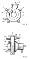
- Figs. 1 and 2 illustrate a preferred embodiment of a centrifugal pump which can be used in accordance with the present invention.
- This kind of a pump is very suitable for pumping medium consistency fiber suspensions.
- this embodiment is a novel modification of a fluidizing centrifugal pump, so called MC-pump, sold and manufactured by A. Ahlstrom Corporation, Finland.
- the housing of the centrifugal pump comprises two axially spaced housing portions, i.e. spiral portions 88 and 90, the radii of which preferably increase towards the respective outlet openings 94, 92.
- said spiral portions may well be circular except the outlets extending from said portions in a preferably tangential direction.
- the spiral portion 90 houses the impeller 80 of the centrifugal pump, whereby the pressure in the outlet opening 92 is much higher than that in the outlet 94.
- the pressure in outlet 92 corresponds to the pressure of an ordinary MC pump.
- the other outlet 94 is arranged in front of the impeller 80, whereby only the rotation created by both the suction of the centrifugal impeller and the fluidizing rotor 78 causes the pulp to flow through the outlet 94, the pressure remaining very low.
- the outlet openings 94, 92 may also be provided with valves 76, as shown in Fig. 1, or the valves may be omitted.
- Fig. 2 shows clearly how to arrange several outlet openings 92, 94 in a centrifugal pump such that the pressure in the outlet openings varies.
- the spiral portions 88 and 90 are equal or different in size, each including at least one outlet opening 92, 94 and optionally a valve (not shown) in connection with said opening.
- Spiral portion 88 is arranged in connection with the inlet channel 22 of the pump, said channel 22 having a clearly smaller diameter than that of the impeller 80.
- the fluidizing rotor 78 which preferably extends through said inlet channel 22 into the pulp vessel.
- the fluidizing rotor 78 is not necessary if the pump impeller is capable of pumping the medium without the aid of the rotor 78.
- the fluidizing rotor is only needed when a medium consistency fiber suspension or like medium is to be pumped by the centrifugal pump.
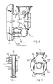
- Fig. 3 shows how the pump housing 96 may be provided with one or more substantially tangential 97 and 98 and/or radial 100 outlet duct or that the duct or ducts may be directioned half tangentially/half radially 102, whereby the direction of the outlets 98, 100, 102 may be chosen such that they extend always toward the free sides of the centrifugal pump and not downwardly towards the floor or towards some apparatus located near the pump. Also, the diameter of the outlets 100, 102 and/or 98 may differ as shown.
- Fig. 3 also shows an outlet 99 arranged in connection with the inlet channel 22 of the centrifugal pump.
- the different ducts receive pulp from the pump in different pressures and as the diameter of the ducts also varies the volume flows in the ducts are seldom equal. It is worthwhile noticing that the volume flow from a duct may be set constant by means of arranging the diameter of the duct to give a certain volume flow at a certain pressure.
- Fig. 4 shows how the outlet openings may extend from the housing 104 not only in a radial direction, as illustrated in Fig. 3, but also in an axial direction 108 or in a direction 110 between radial and axial.
- Figs. 3 and 4 show that the outlet openings 98, 100, 102, 106, 108, 110 may have any desired direction and that the outlet 99 may also be connected to the inlet channel 22 instead of to the volute of housing.
- Fig. 5 shows schematically how one of the branch ducts 112 from the housing 114 may be directly connected to the suction vessel 116, drop leg or like device.
- a portion of the medium introduced into the centrifugal pump is returned via said duct 112 back to the suction vessel 116, for instance, for keeping the bottom layer in said vessel moving, i.e. for preventing the solids of the medium from accumulating at the bottom of the vessel 116.
- Another application for a duct 112 is where the capacity of the pump exceeds the need in the processing line, whereby a portion of the pulp has to be returned back to the pulp vessel.
- a duct leading back to the suction vessel is where the pulp is to be heated by steam, whereby the branch pipe 112 from the vortex chamber could be led through a steam heater back to the suction vessel 116.
- the heated pulp does not necessarily need to be introduced into the bottom portion of the vessel 116.
- the recirculation may be used for compressing the pulp in the vessel 116 downwardly by means of feeding the recirculated, preferably degassed pulp on top of the pulp in said vessel.
- Fig. 6 shows two outlet ducts 119, 120 arranged in the spiral 122 at different radial distances from the axis of the centrifugal pump, leading to different pressures in the outlet ducts.
- Fig. 7 shows four outlet ducts 124, 126, 128, 130 arranged in the housing 132 at different locations along the outline of an imaginary spiral so that different pressures result in addition to the radial location also at different circumferential locations.
- the regulating means i.e. valves or other throttling means, in case they are used, are disposed at a short distance from the inner surface of the vortex chamber.
- the suitable distance has proven to be less than d and preferably less than d/2, when d represents the diameter of the respective outlet.
- a thick fiber suspension for instance, a high consistency pulp, tends to form a rigid fiber plug inside the outlet openings i.e. inside the outlet channel leading from the outlet opening to the valve while the valve is closed or greatly throttled.
- the valves are preferably located in close vicinity to the vortex chamber.
- outlets or outlet openings may be different in size (Fig. 1) or they may be arranged in the vortex chamber such that the pressures acting in the openings are different in magnitude (Figs. 6, 7).
- Figs. 1 to 7 are only exemplary as the number, location and direction of the outlets may greatly differ from the ones shown. Also the direction of the shaft 40 of the centrifugal pump may be either vertical, horizontal or inclined depending on the location of the centrifugal pump. The centrifugal pump may be secured to any convenient part of the vessel containing the medium to be pumped.
- the method and the centrifugal pump in accordance with the invention are intended to cover embodiments wherein the number of regulating means, i.e. valves, is less than the number of outlets.
- the direction of the outlet channels may also vary greatly as they may be arranged, not only as illustrated either radially or tangentially, but also in any direction therebetween.
- the ducts shown may also be used to feed gas, liquid or solids into the pump housing, to be mixed with the medium to be pumped.
- bleaching chemicals of a pulp mill are introduced into the pump and the pulp is pumped further so that the main flow goes to the bleaching tower and a smaller flow is introduced back to the pulp vessel to keep the pulp in the bottom thereof movable.
- dilution liquid may be fed into the pump to lower the consistency of the pulp.
- the pump in accordance with the invention may well be used for pumping all kinds of liquid mediums that need to be delivered from a vessel or the like to a number of different locations.
Landscapes
- Engineering & Computer Science (AREA)
- Mechanical Engineering (AREA)
- General Engineering & Computer Science (AREA)
- Physics & Mathematics (AREA)
- Thermal Sciences (AREA)
- Paper (AREA)
- Structures Of Non-Positive Displacement Pumps (AREA)
- Application Of Or Painting With Fluid Materials (AREA)
Claims (26)
- Verfahren fürs Pumpen einer Fasersuspension mit einer Konsistenz von 5 % bis 25 % in der Papier- und Zellstoffindustrie mittels einer Kreiselpumpe, das folgende Schritte umfaßtgekennzeichnet durchVerbinden eines Einlaßkanals der Pumpe mit der Suspensionsquelle;Einführen der Suspensionsströmung durch den Einlaßkanal in das Pumpengehäuse;Fluidisieren der zu pumpenden Suspension im Einlaßkanal; undHerauspumpen der Suspension aus der Pumpe;Aufteilen der Fasersuspension mit einer Konsistenz von 5 % bis 25 % in Teilströme von wesentlich gleicher Zusammensetzung durchErzeugen einer Druckdifferenz zwischen dem Einlaß und jedem der zumindest zwei Halbstoffauslässe der Pumpe, um die Suspension als wesentlich homogene Teilströme durch die Halbstoffauslässe abzuleiten; undErzeugen eines ausreichend starken Turbulenzfelds um sicherzustellen, daß örtliche Faserkonzentrationen, zum Beispiel Pfropfen oder abgelagerte Fasern, im Pumpengehäuse vom Einlaßkanal zu jedem der Auslässe vermieden werden.
- Verfahren nach Anspruch 1, dadurch gekennzeichnet, daß die Fasersuspension eine mittelkonsistente (8- bis 25-%ige) Fasersuspension der Papier- und Zellstoffindustrie ist.
- Verfahren nach Anspruch 1 oder 2, gekennzeichnet durch den Schritt zur Regelung der Suspensionsströmung durch die Auslässe durch Versehen zumindest eines der Auslässe mit Mitteln zur Regelung der Fasersuspensionsströmung durch den Auslaß.
- Verfahren nach Anspruch 3, dadurch gekennzeichnet, daß sich das Turbulenzfeld zu den Regelungsmitteln hin erstreckt, wodurch verhindert wird, daß die Teil-Faserströmung nahe der Regelungsmittel ein Fasernetzwerk bildet.
- Verfahren nach Anspruch 3, dadurch gekennzeichnet, daß die Strömung durch die Auslässe durch Versehen der Auslässe mit ungleichen Durchmessern geregelt wird.
- Verfahren nach Anspruch 3, dadurch gekennzeichnet, daß die Strömung durch die Auslässe durch Zustandebringen unterschiedlich hoher Drücke in den Auslässen geregelt wird.
- Verfahren nach Anspruch 1 oder 2, gekennzeichnet durch den Schritt zur Rückführung einer Teilströmung der Fasersuspension vom Gehäuse zur Fasersuspensionsquelle.
- Verfahren nach Anspruch 7, dadurch gekennzeichnet, daß die zur Halbstoffquelle rückgeführte Teilströmung durch einen Wärmetauscher fließt.
- Anwendung einer Kreiselpumpe zum Pumpen einer Fasersuspension mit einer Konsistenz von 5 % bis 25 % in der Papier- und Zellstoffindustrie und zum Aufteilen der mittelkonsistenten Fasersuspension in zumindest zwei Teilströme besagter mittelkonsistenter Fasersuspension, welche Pumpe umfaßtein Gehäuse (86, 96, 104, 122, 132),einen Einlaßkanal (22),ein Laufrad (80), das auf einer Welle innerhalb des Gehäuses (86, 96, 104, 122, 132) angeordnet ist, undeinen Fluidisierungsläufer (78), der wesentlich koaxial mit dem Gehäuse (86, 96, 104, 122, 132) auf der Welle angeordnet ist und sich bis in den Einlaßkanal (22) hinein erstreckt,zumindest zwei Fasersuspensionsauslässe (92, 94, 97, 98, 99, 100, 102, 106, 108, 110, 112, 119, 120, 124, 126, 128, 130, 134) fürs Ableiten der Fasersuspension, und wodie Fasersuspensionsauslässe im Gehäuse (86, 96, 104, 122, 132) in verschiedenen Axialpositionen und/oder Radialpositionen und/oder Umfangspositionen in hinsicht auf die Rotationsachse der Pumpe angeordnet sind fürs Aufteilen der zu pumpenden Suspension in Teilströme von wesentlich gleicher Zusammensetzung.
- Anwendung einer Kreiselpumpe nach Anspruch 9, dadurch gekennzeichnet, daß die Fasersuspension eine Konsistenz von 8 % bis 25 % hat.
- Anwendung einer Kreiselpumpe nach Anspruch 9 oder 10, gekennzeichnet durch einen Fluidisierungsläufer (78), der sich im wesentlichen koaxial zum Gehäuse und in den Einlaßkanal (22) hinein erstreckt.
- Anwendung einer Kreiselpumpe nach Anspruch 11, dadurch gekennzeichnet, daß der Fluidisierungsläufer (78) an der Welle befestigt ist.
- Anwendung einer Kreiselpumpe nach Anspruch 11, dadurch gekennzeichnet, daß der Fluidisierungsläufer (78) und/oder das Laufrad (80) Flügel umfassen, die sich von der Welle zu den Auslässen (92, 94) hin erstrecken, um eine Turbulenz im Gehäuse und eine Druckdifferenz zwischen dem Gehäuse und den Auslässen (92, 94) zu erzeugen.
- Anwendung einer Kreiselpumpe nach Anspruch 9 oder 10, dadurch gekennzeichnet, daß zumindest einer der Auslässe (94, 98, 99, 100, 102, 108, 110, 112, 119, 120, 124, 126, 128, 130) mit Mitteln (76) zur Regelung der Fasersuspensionsströmung versehen ist.
- Anwendung einer Kreiselpumpe nach Anspruch 14, dadurch gekennzeichnet, daß die Mittel (76) nahe an den Auslässen (94, 98, 99, 100, 102, 108, 110, 112, 119, 120, 124, 126, 128, 130) zur Regelung der Fasersuspensionsströmung angeordnet sind.
- Anwendung einer Kreiselpumpe nach Anspruch 9 oder 10, dadurch gekennzeichnet, daß die Durchmesser der Auslässe (94, 98, 99, 100, 102, 108, 110, 112, 119, 120, 124, 126, 128, 130) jeweils unterschiedlich groß sind.
- Anwendung einer Kreiselpumpe nach Anspruch 9 oder 10, dadurch gekennzeichnet, daß das Gehäuse (86, 96, 104, 122, 132) einen Gehäuseabschnitt (88, 90) umfaßt, der einen kreisförmigen Querschnitt hat.
- Anwendung einer Kreiselpumpe nach Anspruch 15, dadurch gekennzeichnet, daß die Regelungsmittel (76) derart angeordnet sind, daß der Abstand zwischen den Regelungsmitteln (76) und Auslaß (94, 98, 99, 100, 102, 108, 110, 112, 119, 120, 124, 126, 128, 130) kleiner als der Durchmesser des Auslasses (94, 98, 99, 100, 102, 108, 110, 112, 119, 120, 124, 126, 128, 130) ist.
- Anwendung einer Kreiselpumpe nach Anspruch 9 oder 10, dadurch gekennzeichnet, daß das Gehäuse (86, 96, 104, 122, 132) einen Gehäuseabschnitt (88, 90) umfaßt, der die Form einer Spirale hat, und daß die Auslässe (94, 98, 99, 100, 102, 108, 110, 112, 119, 120, 124, 126, 128, 130) in verschiedenen Umfangspositionen längs der Spirale angeordnet sind.
- Anwendung einer Kreiselpumpe nach Anspruch 9 oder 10, gekennzeichnet durch eine Vielzahl zweiter Auslässe (94, 98, 99, 100, 102, 108, 110, 112, 119, 120, 124, 126, 128, 130), die mit unterschiedlichen Radialabständen zur Achse des Gehäuses angeordnet sind.
- Anwendung einer Kreiselpumpe nach Anspruch 9 oder 10, dadurch gekennzeichnet, daß zumindest einer der Auslässe (99) mit dem Einlaßkanal der Kreiselpumpe (22) verbunden ist.
- Anwendung einer Kreiselpumpe nach Anspruch 9 oder 10, gekennzeichnet durch einen anderen Gehäuseabschnitt (88), der axial im Verhältnis zum Gehäuseabschnitt (90) und in Verbindung damit angeordnet ist, wobei jeder Gehäuseabschnitt (88, 90) zumindest einen Auslaß (92, 94) hat.
- Anwendung einer Kreiselpumpe nach Anspruch 9, 10 oder 22, dadurch gekennzeichnet, daß der Gehäuseabschnitt (88, 90) kreisförmigen, spiraligen Querschnitts oder aus einer Anzahl spiraliger Abschnitte oder einer Kombination davon gebildet ist.
- Anwendung einer Kreiselpumpe nach Anspruch 9, 10 oder 22, dadurch gekennzeichnet, daß zumindest einer der Auslässe (94, 98, 99, 100, 102, 108, 110, 112, 119, 120, 124, 126, 128, 130) des Gehäuses (86, 96, 104, 122, 132) zur Einführung eines Fluids in das Gehäuse (86, 96, 104, 122, 132) benutzt wird.
- Anwendung einer Kreiselpumpe nach Anspruch 11, dadurch gekennzeichnet, daß sich der Fluidisierungsläufer (78) durch den Einlaßkanal (22) hindurch bis in die Fasersuspensionsquelle erstreckt.
- Anwendung einer Kreiselpumpe nach Anspruch 9 oder 22, dadurch gekennzeichnet, daß sich die Auslässe (94, 98, 99, 100, 102, 108, 110, 112, 119, 120, 124, 126, 128, 130) vom Gehäuse (86, 96, 104, 122, 132) in eine tangentiale, axiale oder radiale oder eine dazwischen liegende Richtung erstrecken.
Applications Claiming Priority (2)
| Application Number | Priority Date | Filing Date | Title |
|---|---|---|---|
| US551398 | 1990-07-12 | ||
| US07/551,398 US5228829A (en) | 1986-08-20 | 1990-07-12 | Method and apparatus for dividing flow of high-consistency fiber suspension |
Publications (3)
| Publication Number | Publication Date |
|---|---|
| EP0466167A2 EP0466167A2 (de) | 1992-01-15 |
| EP0466167A3 EP0466167A3 (en) | 1992-10-28 |
| EP0466167B1 true EP0466167B1 (de) | 1999-10-06 |
Family
ID=24201113
Family Applications (1)
| Application Number | Title | Priority Date | Filing Date |
|---|---|---|---|
| EP91111619A Expired - Lifetime EP0466167B1 (de) | 1990-07-12 | 1991-07-12 | Verfahren und Anwendung einer Vorrichtung zum Pumpen eines Mediums |
Country Status (4)
| Country | Link |
|---|---|
| US (1) | US5228829A (de) |
| EP (1) | EP0466167B1 (de) |
| AT (1) | ATE185405T1 (de) |
| DE (1) | DE69131676D1 (de) |
Families Citing this family (11)
| Publication number | Priority date | Publication date | Assignee | Title |
|---|---|---|---|---|
| NO300436B1 (no) * | 1994-10-28 | 1997-05-26 | Norsk Hydro As | Anordning ved utstyr for forbrenning av væsker med höyt partikkelinnhold |
| US7156617B2 (en) * | 2004-09-08 | 2007-01-02 | Attwood Corporation | Dual outlet port pump |
| FI122972B (fi) * | 2005-04-21 | 2012-09-28 | Andritz Oy | Laite massavirtauksen jakamiseksi |
| JP5064012B2 (ja) * | 2005-12-26 | 2012-10-31 | 信越化学工業株式会社 | フッ素含有オルガノポリシロキサン及びこれを含む表面処理剤並びに該表面処理剤で表面処理された物品 |
| WO2010150379A1 (ja) * | 2009-06-25 | 2010-12-29 | 株式会社Tbk | 可変流量式ポンプ |
| FI20135156L (fi) | 2013-02-22 | 2014-08-23 | Wetend Technologies Oy | Järjestely nesteen syöttämiseksi ainakin yhdelle sekoitusasemalle ja menetelmä järjestelyn käyttämiseksi |
| WO2016025259A1 (en) * | 2014-08-15 | 2016-02-18 | Imo Industries, Inc. | Centrifugal pump with integral filter system |
| CN106140766A (zh) * | 2015-04-23 | 2016-11-23 | 北京信智天成科技有限公司 | 循环泵、喷洗系统、清洗机及清洗方法 |
| EP3211245A1 (de) * | 2016-02-23 | 2017-08-30 | Sulzer Management AG | Spiralgehäuse für eine kreiselpumpe |
| DE102016205647B4 (de) * | 2016-04-06 | 2018-11-29 | Voith Patent Gmbh | Ringgatter für eine hydraulische Maschine und Verfahren zum Schließen |
| CN115538120A (zh) * | 2021-06-29 | 2022-12-30 | 博西华电器(江苏)有限公司 | 泵以及具有泵的洗衣装置 |
Family Cites Families (22)
| Publication number | Priority date | Publication date | Assignee | Title |
|---|---|---|---|---|
| GB499357A (en) * | 1938-07-04 | 1939-01-23 | Daimler Benz Ag | Improvements relating to centrifugal blowers |
| US2372538A (en) * | 1943-09-06 | 1945-03-27 | James C White | Flushing means for centrifugal pumps |
| US2504140A (en) * | 1945-04-12 | 1950-04-18 | Lawrence Machine And Pump Corp | Pumping apparatus |
| US2627812A (en) * | 1945-05-21 | 1953-02-10 | Goulds Pumps | Pump |
| US2780490A (en) * | 1952-12-04 | 1957-02-05 | R Sigvardt As | Device for subdividing an airstream |
| US3136254A (en) * | 1961-06-05 | 1964-06-09 | Blackstone Corp | Bi-directional pump |
| US3446151A (en) * | 1967-06-08 | 1969-05-27 | Osby Pump Ind | Submersible centrifugal pump |
| US3540834A (en) * | 1968-09-12 | 1970-11-17 | Worthington Corp | Apparatus for pumping liquids containing solids |
| DE1961272A1 (de) * | 1969-12-06 | 1971-06-16 | Klein Schanzlin & Becker Ag | Verfahren zum selbsttaetigen Axialschubausgleich bei doppelflutigen Kreiselmaschinen |
| US3698830A (en) * | 1971-02-02 | 1972-10-17 | Goyne Pump Co | Vertical centrifugal suction pump |
| US3851993A (en) * | 1973-04-16 | 1974-12-03 | Franklin Mfg Co | Washing machine pump |
| US3928187A (en) * | 1974-11-13 | 1975-12-23 | Ingersoll Rand Canada | Suspension flow control apparatus |
| GB1493205A (en) * | 1976-02-18 | 1977-11-30 | Hill H | Ducted fan arrangement |
| US4596511A (en) * | 1984-06-05 | 1986-06-24 | Eddy Pump Corporation | Eddy pump |
| US4815929A (en) * | 1984-06-05 | 1989-03-28 | Eddy Pump Corporation | Eddy pump |
| SE443007B (sv) * | 1985-03-04 | 1986-02-10 | Kamyr Ab | Silanordning |
| JPS63266193A (ja) * | 1986-09-30 | 1988-11-02 | Jun Taga | ポンプ |
| FI88536C (fi) * | 1987-07-02 | 1995-05-24 | Ahlstroem Oy | Foerfarande och anordning foer pumpning av hoegkonsistent massa |
| US4776758A (en) * | 1987-07-06 | 1988-10-11 | Kamyr Ab | Combined fluidizing and vacuum pump |
| SU1525326A1 (ru) * | 1988-03-10 | 1989-11-30 | Всесоюзный научно-исследовательский институт гидромеханизации, санитарно-технических и специальных строительных работ | Центробежный насос дл перекачивани пульпы |
| SU1571299A1 (ru) * | 1988-05-23 | 1990-06-15 | Комсомольский-на-Амуре политехнический институт | Шнекоцентробежный насос |
| US4981413A (en) * | 1989-04-27 | 1991-01-01 | Ahlstrom Corporation | Pump for and method of separating gas from a fluid to be pumped |
-
1990
- 1990-07-12 US US07/551,398 patent/US5228829A/en not_active Expired - Lifetime
-
1991
- 1991-07-12 DE DE69131676T patent/DE69131676D1/de not_active Expired - Lifetime
- 1991-07-12 AT AT91111619T patent/ATE185405T1/de not_active IP Right Cessation
- 1991-07-12 EP EP91111619A patent/EP0466167B1/de not_active Expired - Lifetime
Also Published As
| Publication number | Publication date |
|---|---|
| EP0466167A2 (de) | 1992-01-15 |
| ATE185405T1 (de) | 1999-10-15 |
| DE69131676D1 (de) | 1999-11-11 |
| US5228829A (en) | 1993-07-20 |
| EP0466167A3 (en) | 1992-10-28 |
Similar Documents
| Publication | Publication Date | Title |
|---|---|---|
| EP0466167B1 (de) | Verfahren und Anwendung einer Vorrichtung zum Pumpen eines Mediums | |
| US4498819A (en) | Multipoint slurry injection junction | |
| US8333825B2 (en) | Apparatus for and method of separating multi-phase fluids | |
| EP0478228B1 (de) | Verfahren und Apparat zur Freisetzung von Gas aus einem Flüssigkeit/Feststoff-Gemisch | |
| US4770604A (en) | Pulp centrifugal pump | |
| US5002671A (en) | Hydro-cyclone with circulation outlet for boundary layer flow | |
| EP0972136B1 (de) | Kreiselflüssigkeitspumpe mit interner gasinjektion | |
| GB1589348A (en) | Hydrocyclone separator arrangement | |
| SE8804009A0 (sv) | Anordning för att sönderdela respektive mala fibermaterial, företrädesvis flis | |
| CN1201048C (zh) | 精碎机 | |
| US4976586A (en) | Pump with separate fluidizing vaned shaft adjacent impeller | |
| CA1183523A (en) | Level seeking vertex free multilevel decantation draft tube mixer | |
| US3152617A (en) | Stream flow valve | |
| EP0597815B1 (de) | Pumpengehäuse Vorrichtung | |
| US4233160A (en) | Hydrocyclone separator arrangement | |
| CA2306374C (en) | Method and apparatus for heating pulps | |
| CN219010805U (zh) | 稀释混合装置和废纸制浆系统 | |
| EP0475985B1 (de) | Verfahren und vorrichtung zum abscheiden schwerer verunreinigungen aus faseraufschwemmungen während des pumpens | |
| GB2266750A (en) | Sheet-metal centrifugal pump casing. | |
| WO1999043439A1 (en) | Device and method for the separation of fluids | |
| WO1996003583A1 (en) | A pulp slurry-handling, centrifugal pump | |
| CN209621621U (zh) | 一种离心泵 | |
| SU1414437A1 (ru) | Центробежный диспергатор дл приготовлени эмульсии гидрофобизирующего вещества | |
| CN1079276A (zh) | 离心泵 | |
| GB2233473A (en) | Fluidic control devices |
Legal Events
| Date | Code | Title | Description |
|---|---|---|---|
| PUAI | Public reference made under article 153(3) epc to a published international application that has entered the european phase |
Free format text: ORIGINAL CODE: 0009012 |
|
| 17P | Request for examination filed |
Effective date: 19910712 |
|
| AK | Designated contracting states |
Kind code of ref document: A2 Designated state(s): AT DE ES FR GB SE |
|
| PUAL | Search report despatched |
Free format text: ORIGINAL CODE: 0009013 |
|
| AK | Designated contracting states |
Kind code of ref document: A3 Designated state(s): AT DE ES FR GB SE |
|
| 17Q | First examination report despatched |
Effective date: 19940209 |
|
| GRAG | Despatch of communication of intention to grant |
Free format text: ORIGINAL CODE: EPIDOS AGRA |
|
| GRAG | Despatch of communication of intention to grant |
Free format text: ORIGINAL CODE: EPIDOS AGRA |
|
| GRAG | Despatch of communication of intention to grant |
Free format text: ORIGINAL CODE: EPIDOS AGRA |
|
| GRAH | Despatch of communication of intention to grant a patent |
Free format text: ORIGINAL CODE: EPIDOS IGRA |
|
| GRAH | Despatch of communication of intention to grant a patent |
Free format text: ORIGINAL CODE: EPIDOS IGRA |
|
| GRAA | (expected) grant |
Free format text: ORIGINAL CODE: 0009210 |
|
| AK | Designated contracting states |
Kind code of ref document: B1 Designated state(s): AT DE ES FR GB SE |
|
| PG25 | Lapsed in a contracting state [announced via postgrant information from national office to epo] |
Ref country code: FR Free format text: LAPSE BECAUSE OF FAILURE TO SUBMIT A TRANSLATION OF THE DESCRIPTION OR TO PAY THE FEE WITHIN THE PRESCRIBED TIME-LIMIT Effective date: 19991006 Ref country code: ES Free format text: THE PATENT HAS BEEN ANNULLED BY A DECISION OF A NATIONAL AUTHORITY Effective date: 19991006 |
|
| REF | Corresponds to: |
Ref document number: 185405 Country of ref document: AT Date of ref document: 19991015 Kind code of ref document: T |
|
| REF | Corresponds to: |
Ref document number: 69131676 Country of ref document: DE Date of ref document: 19991111 |
|
| PG25 | Lapsed in a contracting state [announced via postgrant information from national office to epo] |
Ref country code: DE Free format text: LAPSE BECAUSE OF FAILURE TO SUBMIT A TRANSLATION OF THE DESCRIPTION OR TO PAY THE FEE WITHIN THE PRESCRIBED TIME-LIMIT Effective date: 20000108 |
|
| EN | Fr: translation not filed | ||
| PG25 | Lapsed in a contracting state [announced via postgrant information from national office to epo] |
Ref country code: GB Free format text: LAPSE BECAUSE OF NON-PAYMENT OF DUE FEES Effective date: 20000712 |
|
| PLBE | No opposition filed within time limit |
Free format text: ORIGINAL CODE: 0009261 |
|
| STAA | Information on the status of an ep patent application or granted ep patent |
Free format text: STATUS: NO OPPOSITION FILED WITHIN TIME LIMIT |
|
| 26N | No opposition filed | ||
| GBPC | Gb: european patent ceased through non-payment of renewal fee |
Effective date: 20000712 |
|
| PGFP | Annual fee paid to national office [announced via postgrant information from national office to epo] |
Ref country code: AT Payment date: 20100714 Year of fee payment: 20 Ref country code: SE Payment date: 20100715 Year of fee payment: 20 |
|
| REG | Reference to a national code |
Ref country code: SE Ref legal event code: EUG |