EP0465745A2 - A sailing boat model adapted for exhibition and for sailing on the water - Google Patents
A sailing boat model adapted for exhibition and for sailing on the water Download PDFInfo
- Publication number
- EP0465745A2 EP0465745A2 EP90311911A EP90311911A EP0465745A2 EP 0465745 A2 EP0465745 A2 EP 0465745A2 EP 90311911 A EP90311911 A EP 90311911A EP 90311911 A EP90311911 A EP 90311911A EP 0465745 A2 EP0465745 A2 EP 0465745A2
- Authority
- EP
- European Patent Office
- Prior art keywords
- hull
- model
- keel
- sailing boat
- rudder
- Prior art date
- Legal status (The legal status is an assumption and is not a legal conclusion. Google has not performed a legal analysis and makes no representation as to the accuracy of the status listed.)
- Granted
Links
Images


Classifications
-
- A—HUMAN NECESSITIES
- A63—SPORTS; GAMES; AMUSEMENTS
- A63H—TOYS, e.g. TOPS, DOLLS, HOOPS OR BUILDING BLOCKS
- A63H23/00—Toy boats; Floating toys; Other aquatic toy devices
- A63H23/02—Boats; Sailing boats
Definitions
- the present invention relates to a sailing boat model having auxiliary members which are detachably connected on the model, and more specifically to a sailing boat model which can be sailed on the water by mounting auxiliary members on the hull body of the model adapted for exhibition.
- a sailing boat model for example a yacht model, adapted for exhibition, which has a configuration similar to an actual sailing boat that is pars of the model such as a hull, a mast, a rudder, etc. have relative dimensions which simulate an actual sailing boat, is apt to turn over on its side as the weight of its sail is large compared with the size of the hull of the model. Moreover, the rudder area of the model is small compared with the weight of the model so that sufficient maneuverability can not be obtained.
- a sailing boat model adapted for exhibition must have a configuration similar to an actual sailing boat. But the sail area of the model is small compared with the weight of the model so that, when the wind is gentle, the model can not sail unless the weight of the model is reduced. On the contrary, if the weight of the model is reduced, the model is apt to sway under a strong wind and to turn over on its side.
- the sailing boat model adapted for exhibition is not suitable for actual sailing on the water.
- a sailing boat model adapted for actual sailing must have a configuration remarkably different from that of a model adapted for exhibition.
- a sailing boat model adapted for exhibition and for actual sailing on water, comprising a hull, keel means provided on a bottom portion of a midship of the hull to extend downward from the hull, rudder means provided on a bottom portion of a stern of the hull, mast means provided on the hull to extend upward from the hull, sail means connected to the mast means, the hull, the keel means, the rudder means, the mast means and the sail means having relative dimensions which simulate an actual sailing boat, and balancing weight means detachably attached to the bottom portion of the midship of the hull to lower a center of gravity of the sailing boat model when it is sailed on the water.
- the balancing weight means comprises auxiliary keel means including keel body means to extend downward from the bottom of the hull and having balancing mass means provided on a lower end portion of the keel body means.
- the model further comprises adjusting means to adjust a posision of the balancing mass means along a line extending toward a bow of the sailing boat model with an up-grade.
- said model further comprises stabilizing fin means provided on a lower end of the keel body means.
- said model further comprises auxiliary buoyant means provided on an upper part of the keel body means.
- said model further comprises annular wire means provided on a fore end of the keel body means.
- a sailing boat model adapted for exhibition and for actual sailing on water, comprising a hull, keel means provided on a bottom portion of of a midship of the hull to extend downward from the hull, rudder means provided on a bottom portion of a stern of the hull, mast means provided on the hull to extend upward from the hull, sail means connected to the mast means, the hull, the keel means, the rudder means, the mast means and the sail means having relative dimensions which simulate an actual sailing boat, and auxiliary rudder means detachably attached to the rudder means.
- At least a part of the auxiliary keel means and at least a part of the auxiliary rudder means are made of a transparent material.
- a sailing boat model which has a configuration similar to an actual sailing boat and is adapted for exhibition is provided.
- balancing weight means is detachably attached to the bottom portion of the midship of the hull so as to increase the stability of the model against rolling.
- the balancing weight means comprises auxiliary keel means including keel body means to extend downward from the bottom of the hull and having balancing mass means provided on a lower end portion of the keel body means, the keel body means prevents the model from swaying, while the balancing mass means increases the stability of the model against rolling.
- the model can sail on the water.
- the auxiliary rudder means helps to improve the model's ability to maintain its course.
- the model rolls excessively so that the center of the wind force acting on the sail means moves toward the stern of the model and thus it does not coincide with the yaw axis of the model any more.
- the model turns windward, and thus the model can not maintain its course any more.
- adjusting means to adjust the position of the balancing mass means along a line extending toward a bow of the sailing boat model with an up-grade so as to prevent such an above phenomenon from occuring.
- the balancing mass means provided on the lower end of the keel body means is lowered.
- the position of the balancing mass means moves downward, which increases the stability of the model against rolling, and at the same time, the position of the balancing mass means moves toward the stern of the model, which causes the aft trim of the model to increase and causes the yaw axis of the model to move tward the stern of the model.
- the yaw axis of the model coincides with the center of the wind force acting on the sail, and thus the model has improved ability to maintain its course.
- Stabilizing fin means provided on the lower end of the keel body means decreases the pitching and the rolling of the model so that the sailing speed of the model is kept high.
- the auxiliary buoyant means provided on an upper part of the keel body means keeps a proper model draft so that the hydraulic resistance on the hull of the model decreases.
- the auxiliary buoyant means also increases the stability of the model against rolling.
- the auxiliary rudder means detachably attached to the rudder means compensates for the insufficient rudder area of the model so that the maneuverability of the model is improved.
- the annular wire means provide on a fore end of the keel body means operates as follows. When the annular wire means contacts with an obstacle during the sailing of the model on the water, the model turns around the contact point between the annular wire means and the obstacle so that the model can easily get away from the obstacle.
- the sailing boat model becomes even more similar to an actual sailing boat even if it is provided with the auxiliary keel means or the auxiliary rudder means if at least a part of the auxiliary keel means or the auxiliary rudder means is made of a transparent material, as they then could not be seen in the water.
- the yacht model has a hull 1 , a keel 2 provided on the bottom of the midship portion of the hull 1, and a rudder 3 provided on the bottom of the stern portion of the hull 1.
- the hull 1 is provided with a mast 4 extending upward.
- the mast 4 is provided with a main sail 5 at its rear side, and a jib sail 6 at its front side.
- the above mentioned model has a configuration similar to that of an actual yacht, that is the hull 1, the keel 2, the rudder 3, the mast 4, the sails 5 and 6 have relative dimension which simulate an actual sailing yacht.
- the model is exhibited on a proper base frame or hung on a wall.
- an auxiliary keel 7 having a weight 8 on its lower end is provided so as to prevent the hull 1 from turning over on its side.
- the auxiliary keel 7 has connecting members 7a, 7b, each having a flange-like configuration, at its upper portion, and a cutout disposed between the connecting members 7a, 7b for preventing the auxiliary keel 7 from interfering with the keel 2.
- the auxiliary keel 7 is mounted on the hull 1 by screwing connecting screws 1b into tapped holes 1a provided on the bottom of the hull 1 and each having a construction of a cap nut for waterproofing, so as to fix the flange-like connecting members 7a, 7b on the hull 1 from its outside along the center line of the hull 1 with the cutout between connecting members 7a, 7b facing the keel 2.
- the auxiliary keel 7 can be easily connected to and disconnected from the hull 1.
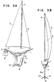
- FIGS 3A, 3B show another embodiment of the present invention.
- the auxiliary keel 7 is provided with stabilizing fins 10, 10 on both sides of the lower end of its rear portion.
- Fixed to the fore part of the auxiliary keel 7 is a connecting member 8a which is adapted to hold the weight 8 and is able to adjust the height at which the weight 8 is mounted to the keel 7.
- the stabilizing fins 10, 10 and the weight 8 can be used as a tripod to make the model stand up straight, with the auxiliary keel 7 being mounted on the hull 1.
- the connecting member 8a is mounted to the fore part of the auxiliary keel 7 by screwing the connecting member 8a on the fore part of the auxiliary keel 7 using a pair of upper tapped holes 8b, 8b or a pair of lower tapped holes 8c, 8c which are disposed on the the auxiliary keel 7 along the leading edge of the keel 7, in accordance with the height at which the weight 8 is to be mounted on the keel 7.
- the height at which the weight 8 is mounted to the keel 7 can be adjusted.
- the leading edge of the keel 7 is inclined to form a line extending toward a bow of the model with an up-grade as shown in Figure 3A so that the position of the weight 8 moves toward the stern of the model 1 as the position of the weight 8 moves downward.
- an auxiliary rudder 9 is connected to the rudder 3 by inserting the rudder 3 into a channel 9a disposed on the upper portion of the auxiliary rudder 9. Maneuverability of the model yacht is improved by using the auxiliary rudder 9.
- Figures 7A, 7B show still another embodiment of the present invention.
- the auxiliary keel 7 is provided with auxiliary buoyant means 11 made of a foaming material on both sides of its upper portion.
- the auxiliary buoyant means 11 may be made of a hollow material.
- Figure 8 shows still another embodiment of the present invention.
- the auxiliary keel 7 is provided with an annular wire 12 on its fore end.
- the yacht model becomes even more similar to the actual yacht even if it is provided with the auxiliary keel 7 and the auxiliary rudder 9 if the auxiliary keel 7 and the auxiliary rudder 9 are made of a transparent material such as transparent plastic, as they then could not be seen in the water.
Abstract
Description
- The present invention relates to a sailing boat model having auxiliary members which are detachably connected on the model, and more specifically to a sailing boat model which can be sailed on the water by mounting auxiliary members on the hull body of the model adapted for exhibition.
- A sailing boat model, for example a yacht model, adapted for exhibition, which has a configuration similar to an actual sailing boat that is pars of the model such as a hull, a mast, a rudder, etc. have relative dimensions which simulate an actual sailing boat, is apt to turn over on its side as the weight of its sail is large compared with the size of the hull of the model. Moreover, the rudder area of the model is small compared with the weight of the model so that sufficient maneuverability can not be obtained.
- A sailing boat model adapted for exhibition must have a configuration similar to an actual sailing boat. But the sail area of the model is small compared with the weight of the model so that, when the wind is gentle, the model can not sail unless the weight of the model is reduced. On the contrary, if the weight of the model is reduced, the model is apt to sway under a strong wind and to turn over on its side.
- As described above, the sailing boat model adapted for exhibition is not suitable for actual sailing on the water. As a result, a sailing boat model adapted for actual sailing must have a configuration remarkably different from that of a model adapted for exhibition.
- It is therefore the object of the present invention to provide a sailing boat model which is adapted for exhibition and also adapted for actual sailing on the water.
- In accordance with the present invention, there is provided a sailing boat model adapted for exhibition and for actual sailing on water, comprising a hull, keel means provided on a bottom portion of a midship of the hull to extend downward from the hull, rudder means provided on a bottom portion of a stern of the hull, mast means provided on the hull to extend upward from the hull, sail means connected to the mast means, the hull, the keel means, the rudder means, the mast means and the sail means having relative dimensions which simulate an actual sailing boat, and balancing weight means detachably attached to the bottom portion of the midship of the hull to lower a center of gravity of the sailing boat model when it is sailed on the water.
- In a preferable embodiment of the present invention, the balancing weight means comprises auxiliary keel means including keel body means to extend downward from the bottom of the hull and having balancing mass means provided on a lower end portion of the keel body means.
- In another preferable embodiment of the present invention, the model further comprises adjusting means to adjust a posision of the balancing mass means along a line extending toward a bow of the sailing boat model with an up-grade.
- In still another preferable embodiment of the present invention, said model further comprises stabilizing fin means provided on a lower end of the keel body means.
- In another preferable embodiment of the present invention, said model further comprises auxiliary buoyant means provided on an upper part of the keel body means.
- In still another preferable embodiment of the present invention, said model further comprises annular wire means provided on a fore end of the keel body means.
- In a preferable aspect of the present invention, there is provided a sailing boat model adapted for exhibition and for actual sailing on water, comprising a hull, keel means provided on a bottom portion of of a midship of the hull to extend downward from the hull, rudder means provided on a bottom portion of a stern of the hull, mast means provided on the hull to extend upward from the hull, sail means connected to the mast means, the hull, the keel means, the rudder means, the mast means and the sail means having relative dimensions which simulate an actual sailing boat, and auxiliary rudder means detachably attached to the rudder means.
- In a preferable embodiment of the present invention, at least a part of the auxiliary keel means and at least a part of the auxiliary rudder means are made of a transparent material.
- According to the features of the present invention, a sailing boat model which has a configuration similar to an actual sailing boat and is adapted for exhibition is provided. When the model is sailed on the water, balancing weight means is detachably attached to the bottom portion of the midship of the hull so as to increase the stability of the model against rolling. Provided the balancing weight means comprises auxiliary keel means including keel body means to extend downward from the bottom of the hull and having balancing mass means provided on a lower end portion of the keel body means, the keel body means prevents the model from swaying, while the balancing mass means increases the stability of the model against rolling. Thus the model can sail on the water. The auxiliary rudder means helps to improve the model's ability to maintain its course. When the wind is strong, the model rolls excessively so that the center of the wind force acting on the sail means moves toward the stern of the model and thus it does not coincide with the yaw axis of the model any more. As a result, the model turns windward, and thus the model can not maintain its course any more. In accordance with the present invention, there is provided adjusting means to adjust the position of the balancing mass means along a line extending toward a bow of the sailing boat model with an up-grade so as to prevent such an above phenomenon from occuring. When the wind is strong, the balancing mass means provided on the lower end of the keel body means is lowered. Thus the position of the balancing mass means moves downward, which increases the stability of the model against rolling, and at the same time, the position of the balancing mass means moves toward the stern of the model, which causes the aft trim of the model to increase and causes the yaw axis of the model to move tward the stern of the model. As a result, the yaw axis of the model coincides with the center of the wind force acting on the sail, and thus the model has improved ability to maintain its course. Stabilizing fin means provided on the lower end of the keel body means decreases the pitching and the rolling of the model so that the sailing speed of the model is kept high. The auxiliary buoyant means provided on an upper part of the keel body means keeps a proper model draft so that the hydraulic resistance on the hull of the model decreases. The auxiliary buoyant means also increases the stability of the model against rolling. The auxiliary rudder means detachably attached to the rudder means compensates for the insufficient rudder area of the model so that the maneuverability of the model is improved. The annular wire means provide on a fore end of the keel body means operates as follows. When the annular wire means contacts with an obstacle during the sailing of the model on the water, the model turns around the contact point between the annular wire means and the obstacle so that the model can easily get away from the obstacle. The sailing boat model becomes even more similar to an actual sailing boat even if it is provided with the auxiliary keel means or the auxiliary rudder means if at least a part of the auxiliary keel means or the auxiliary rudder means is made of a transparent material, as they then could not be seen in the water.
- The above and other objects and features of the present invention will become apparent from the following description of the preferred embodiments when taken in conjunction with the acocompanying drawings, in which,
- Figure 1 is a side view showing a yacht model in accordance with an embodiment of the present invention.
- Figure 2 is a cross sectional view of a part connecting the auxiliary keel to the hull of the model.
- Figure 3A is a side view showing a yacht model in accordance with another embodiment of the present invention.
- Figure 3B is a front view of the model in Figure 3A.
- Figure 4 is a perspective view showing a procedure for connecting the weight to the auxiliary keel in the embodiment of Figure 3A.
- Figure 5 is a perspective view showing an auxiliary rudder in accordance with the present invention.
- Figure 6 is a side view showing a procedure for connecting the auxiliary rudder of Figure 5 to the rudder of the model.
- Figure 7A is a side view showing another embodiment of the present invention which is provided with the auxiliary buoyant means.
- Figure 7B is a front view of the model in Figure 7A.
- Figure 8 is a perspective view showing another embodiment of the present invention which is provided with the annular wire at its auxiliary keel.
- Referring to Figure 1, there is shown a yacht model. The yacht model has a hull 1 , a
keel 2 provided on the bottom of the midship portion of the hull 1, and arudder 3 provided on the bottom of the stern portion of the hull 1. The hull 1 is provided with amast 4 extending upward. Themast 4 is provided with amain sail 5 at its rear side, and ajib sail 6 at its front side. The above mentioned model has a configuration similar to that of an actual yacht, that is the hull 1, thekeel 2, therudder 3, themast 4, thesails auxiliary keel 7 having aweight 8 on its lower end is provided so as to prevent the hull 1 from turning over on its side. Theauxiliary keel 7 has connectingmembers members auxiliary keel 7 from interfering with thekeel 2. As shown in Figure 2, theauxiliary keel 7 is mounted on the hull 1 by screwing connectingscrews 1b into tappedholes 1a provided on the bottom of the hull 1 and each having a construction of a cap nut for waterproofing, so as to fix the flange-like connectingmembers members keel 2. Thus, theauxiliary keel 7 can be easily connected to and disconnected from the hull 1. - Figures 3A, 3B show another embodiment of the present invention. In this embodiment, the
auxiliary keel 7 is provided with stabilizingfins auxiliary keel 7 is a connectingmember 8a which is adapted to hold theweight 8 and is able to adjust the height at which theweight 8 is mounted to thekeel 7. By this construction, the stabilizingfins weight 8 can be used as a tripod to make the model stand up straight, with theauxiliary keel 7 being mounted on the hull 1. As shown in Figure 4, the connectingmember 8a is mounted to the fore part of theauxiliary keel 7 by screwing the connectingmember 8a on the fore part of theauxiliary keel 7 using a pair of upper tappedholes holes auxiliary keel 7 along the leading edge of thekeel 7, in accordance with the height at which theweight 8 is to be mounted on thekeel 7. Thus, the height at which theweight 8 is mounted to thekeel 7 can be adjusted. Moreover, the leading edge of thekeel 7 is inclined to form a line extending toward a bow of the model with an up-grade as shown in Figure 3A so that the position of theweight 8 moves toward the stern of the model 1 as the position of theweight 8 moves downward. As shown in Figures 5 and 6, anauxiliary rudder 9 is connected to therudder 3 by inserting therudder 3 into achannel 9a disposed on the upper portion of theauxiliary rudder 9. Maneuverability of the model yacht is improved by using theauxiliary rudder 9. - Figures 7A, 7B show still another embodiment of the present invention. In this embodiment, the
auxiliary keel 7 is provided with auxiliary buoyant means 11 made of a foaming material on both sides of its upper portion. By this construction, the yacht model draft becomes shallow so that the hydraulic resistance of the hull 1 becomes small, and at the same time, stability against rolling by a strong wind increases. The auxiliary buoyant means 11 may be made of a hollow material. - Figure 8 shows still another embodiment of the present invention. In this embodiment, the
auxiliary keel 7 is provided with anannular wire 12 on its fore end. By this construction, when theannular wire 12 contacts with an obstacle during the sailing of the yacht model on the water, the yacht model turns around the contact point between theannular wire 12 and the obstacle so that the yacht model can easily get away from the obstacle. - In the aforementioned embodiments, the yacht model becomes even more similar to the actual yacht even if it is provided with the
auxiliary keel 7 and theauxiliary rudder 9 if theauxiliary keel 7 and theauxiliary rudder 9 are made of a transparent material such as transparent plastic, as they then could not be seen in the water.
Claims (9)
- A sailing boat model adapted for exhibition and for actual sailing on water, and comprising a hull (1); keel means (2) provided on a bottom portion of a midship of the hull to extend downward from the hull; rudder means (3) provided on a bottom portion of a stern of the hull; mast means (4) provided on the hull to extend upward from the hull; sail means (5) connected to the mast means; the hull, the keel means, the rudder means, the mast means and the sail means having relative dimensions which simulate an actual sailing boat; and, balancing weight means (7,8) detachably attached to the bottom portion of the midship of the hull to lower a center of gravity of the sailing boat model when it is sailed on the water.
- A sailing boat model in accordance with claim 1, wherein the balancing weight means comprises auxiliary keel means including keel body means (7) to extend downward from the bottom of the hull and having balancing mass means (8) provided on a lower end portion of the keel body means.
- A sailing boat model in accordance with claim 2, further comprising adjusting means (8a) to adjust a position of the balancing mass means (8) along a line extending toward a bow of the sailing boat model with an up-grade.
- A sailing boat model in accordance with claim 2 or claim 3, further comprising stabilizing fin means (10) provided on the lower end portion of the keel body means (7).
- A sailing boat model in accordance with any one of claims 2 to 4, further comprising auxiliary buoyant means (11) provided on an upper part of the keel body means (7).
- A sailing boat model 1n accordance with any one of claims 2 to 5, further comprising annular wire means (12) provided on a fore end of the keel body means (7).
- A sailing boat model in accordance with any one of claims 2 to 6, wherein at least a part of the auxiliary keel means (7) is made of a transparent material.
- A sailing boat model adapted for exhibition and for actual sailing on water, and comprising a hull (1); keel means (2) provided on a bottom portion of a midship of the hull to extend downward from the hull; rudder means (3) provided on a bottom portion of a stern of the hull; mast means (4) provided on the hull to extend upward from the hull; sail means (5) connected to the mast means; the hull, the keel means, the rudder means, the mast means and the sail means having relative dimensions which simulate an actual sailing boat; and, auxiliary rudder means (9) detachably attached to the rudder means.
- A sailing boat model in accordance with claim 8, wherein at least a part of the auxiliary rudder means (9) is made of a transparent material.
Applications Claiming Priority (2)
| Application Number | Priority Date | Filing Date | Title |
|---|---|---|---|
| JP2181744A JPH0661393B2 (en) | 1990-07-10 | 1990-07-10 | A sailboat model suitable for water sailing and exhibition |
| JP181744/90 | 1990-07-10 |
Publications (3)
| Publication Number | Publication Date |
|---|---|
| EP0465745A2 true EP0465745A2 (en) | 1992-01-15 |
| EP0465745A3 EP0465745A3 (en) | 1992-03-18 |
| EP0465745B1 EP0465745B1 (en) | 1994-12-28 |
Family
ID=16106129
Family Applications (1)
| Application Number | Title | Priority Date | Filing Date |
|---|---|---|---|
| EP90311911A Expired - Lifetime EP0465745B1 (en) | 1990-07-10 | 1990-10-31 | A sailing boat model adapted for exhibition and for sailing on the water |
Country Status (4)
| Country | Link |
|---|---|
| US (1) | US5069648A (en) |
| EP (1) | EP0465745B1 (en) |
| JP (1) | JPH0661393B2 (en) |
| DE (1) | DE69015628T2 (en) |
Cited By (1)
| Publication number | Priority date | Publication date | Assignee | Title |
|---|---|---|---|---|
| CN109612632A (en) * | 2018-11-02 | 2019-04-12 | 中国航空工业集团公司西安飞机设计研究所 | A kind of general-purpose aircraft rudder weight balancing inspection method |
Families Citing this family (11)
| Publication number | Priority date | Publication date | Assignee | Title |
|---|---|---|---|---|
| US5784976A (en) * | 1997-02-05 | 1998-07-28 | Burdick; James F. | Weighted daggerboard stabilizer for wind surfing apparatus |
| WO1998033701A1 (en) * | 1997-02-05 | 1998-08-06 | Burdick James F | Weighted daggerboard stabilizer for windsurfing apparatus |
| NZ336760A (en) * | 1999-07-12 | 2002-09-27 | Dianne Conroy | Water craft for fishing with sail that can be moved from raised to lowered position by operator from shore |
| JP2002369745A (en) * | 2001-06-15 | 2002-12-24 | Taimatsu Shokuhin Kk | Decoration set for rice cake offering |
| CN101475051B (en) * | 2008-01-02 | 2010-11-10 | 北京有色金属研究总院 | Ship hull externally hung anti-wind wave tungsten alloy bob-weight for sailing vessel |
| US7784417B2 (en) * | 2008-11-13 | 2010-08-31 | Jensen Christian H | Sailboat with a canting ballast system |
| JP5316607B2 (en) | 2010-08-11 | 2013-10-16 | 横浜ゴム株式会社 | Tire puncture sealant |
| US10525369B2 (en) | 2012-05-16 | 2020-01-07 | Toyosity, LLC | Interchangeable components for water and convertible toys |
| US9474983B2 (en) | 2012-05-16 | 2016-10-25 | Toyosity, LLC | Surfing toy |
| US9352239B2 (en) | 2012-05-16 | 2016-05-31 | Toyosity, LLC | Toy surfboard |
| US8894460B1 (en) | 2012-05-16 | 2014-11-25 | Toyosity, LLC | Toy surfboard |
Citations (3)
| Publication number | Priority date | Publication date | Assignee | Title |
|---|---|---|---|---|
| GB234280A (en) * | 1924-05-22 | 1925-05-28 | George Stevenson | Improvements in toy or model vessels |
| DE3227348A1 (en) * | 1982-07-22 | 1984-02-02 | Harald 3015 Wennigsen Diesinger | Lifting and rescue apparatus for ships |
| US4599964A (en) * | 1984-12-21 | 1986-07-15 | Kenney Thomas A | Sailboat hull |
Family Cites Families (7)
| Publication number | Priority date | Publication date | Assignee | Title |
|---|---|---|---|---|
| US685648A (en) * | 1901-06-04 | 1901-10-29 | Albert Schoenhut | Boat. |
| DE443786C (en) * | 1925-02-19 | 1927-05-06 | Carl August Hefter | Folding boat for play purposes |
| US1918543A (en) * | 1931-07-27 | 1933-07-18 | Chein & Company J | Sail boat |
| GB413930A (en) * | 1933-11-13 | 1934-07-26 | Alfred Mallory Todd | Improvements relating to toy boats |
| GB1115663A (en) * | 1966-03-01 | 1968-05-29 | Willem Frederik Vonck | Improvements in yachts having centre-boards |
| US3871127A (en) * | 1973-01-04 | 1975-03-18 | Desmond Heath | Model sailing ship |
| US4548149A (en) * | 1983-11-04 | 1985-10-22 | Del Raso Americo | Rudder for aquatic craft |
-
1990
- 1990-07-10 JP JP2181744A patent/JPH0661393B2/en not_active Expired - Lifetime
- 1990-10-30 US US07/605,375 patent/US5069648A/en not_active Expired - Fee Related
- 1990-10-31 DE DE69015628T patent/DE69015628T2/en not_active Expired - Fee Related
- 1990-10-31 EP EP90311911A patent/EP0465745B1/en not_active Expired - Lifetime
Patent Citations (3)
| Publication number | Priority date | Publication date | Assignee | Title |
|---|---|---|---|---|
| GB234280A (en) * | 1924-05-22 | 1925-05-28 | George Stevenson | Improvements in toy or model vessels |
| DE3227348A1 (en) * | 1982-07-22 | 1984-02-02 | Harald 3015 Wennigsen Diesinger | Lifting and rescue apparatus for ships |
| US4599964A (en) * | 1984-12-21 | 1986-07-15 | Kenney Thomas A | Sailboat hull |
Cited By (1)
| Publication number | Priority date | Publication date | Assignee | Title |
|---|---|---|---|---|
| CN109612632A (en) * | 2018-11-02 | 2019-04-12 | 中国航空工业集团公司西安飞机设计研究所 | A kind of general-purpose aircraft rudder weight balancing inspection method |
Also Published As
| Publication number | Publication date |
|---|---|
| DE69015628T2 (en) | 1995-05-11 |
| JPH0471587A (en) | 1992-03-06 |
| JPH0661393B2 (en) | 1994-08-17 |
| EP0465745A3 (en) | 1992-03-18 |
| DE69015628D1 (en) | 1995-02-09 |
| EP0465745B1 (en) | 1994-12-28 |
| US5069648A (en) | 1991-12-03 |
Similar Documents
| Publication | Publication Date | Title |
|---|---|---|
| EP0465745B1 (en) | A sailing boat model adapted for exhibition and for sailing on the water | |
| US4819576A (en) | Hydrofoil - submarine vessel system | |
| US3762353A (en) | High speed sailboat | |
| US5471942A (en) | Hydrofoil sailboard with supercavitating canard hydrofoil | |
| WO1987002320A1 (en) | Fast self righting catamaran | |
| US5063869A (en) | Wing type sailing yacht | |
| US6789490B2 (en) | Ship constructions for achieving stability at high speed through the use of multiple, low wave-making resistance, submerged hullform pods and control fins | |
| US6789489B1 (en) | Sailboat with gimbaled mast and keel | |
| WO2001000483A8 (en) | Sailing boat | |
| JPH0788199B2 (en) | Sailboats and sailboat propulsion devices | |
| US4843987A (en) | Heel counteracting airfoil | |
| EP0855984B1 (en) | Hydrofoil assisted trimaran | |
| US6070544A (en) | Boat with outriggers | |
| US4280428A (en) | Non-heeling sailboat | |
| US4599964A (en) | Sailboat hull | |
| US6073568A (en) | Boat with outriggers | |
| US4784075A (en) | Watercraft with righting aid | |
| US5647294A (en) | Boat with adjustable outriggers | |
| US6325009B1 (en) | Sailboat for sailing in shallow water | |
| EP0152461B1 (en) | Keel structures for sailing vessels | |
| US4686923A (en) | Sailboat keel having a cantilevered trailing edge flap | |
| US7677190B2 (en) | Slotted hulls for boats | |
| US6382121B2 (en) | Boat ballast system | |
| JP2615348B2 (en) | Rollover prevention device with wing ring on hull | |
| JP3208544B2 (en) | Semi-submerged catamaran |
Legal Events
| Date | Code | Title | Description |
|---|---|---|---|
| PUAI | Public reference made under article 153(3) epc to a published international application that has entered the european phase |
Free format text: ORIGINAL CODE: 0009012 |
|
| 17P | Request for examination filed |
Effective date: 19901221 |
|
| AK | Designated contracting states |
Kind code of ref document: A2 Designated state(s): DE GB |
|
| PUAL | Search report despatched |
Free format text: ORIGINAL CODE: 0009013 |
|
| AK | Designated contracting states |
Kind code of ref document: A3 Designated state(s): DE GB |
|
| 17Q | First examination report despatched |
Effective date: 19930928 |
|
| GRAA | (expected) grant |
Free format text: ORIGINAL CODE: 0009210 |
|
| AK | Designated contracting states |
Kind code of ref document: B1 Designated state(s): DE GB |
|
| REF | Corresponds to: |
Ref document number: 69015628 Country of ref document: DE Date of ref document: 19950209 |
|
| PLBE | No opposition filed within time limit |
Free format text: ORIGINAL CODE: 0009261 |
|
| STAA | Information on the status of an ep patent application or granted ep patent |
Free format text: STATUS: NO OPPOSITION FILED WITHIN TIME LIMIT |
|
| 26N | No opposition filed | ||
| PGFP | Annual fee paid to national office [announced via postgrant information from national office to epo] |
Ref country code: DE Payment date: 19981030 Year of fee payment: 9 |
|
| PGFP | Annual fee paid to national office [announced via postgrant information from national office to epo] |
Ref country code: GB Payment date: 19981106 Year of fee payment: 9 |
|
| PG25 | Lapsed in a contracting state [announced via postgrant information from national office to epo] |
Ref country code: GB Free format text: LAPSE BECAUSE OF NON-PAYMENT OF DUE FEES Effective date: 19991031 |
|
| GBPC | Gb: european patent ceased through non-payment of renewal fee |
Effective date: 19991031 |
|
| PG25 | Lapsed in a contracting state [announced via postgrant information from national office to epo] |
Ref country code: DE Free format text: LAPSE BECAUSE OF NON-PAYMENT OF DUE FEES Effective date: 20000801 |