EP0464411B1 - Apparatus for the manufacture of plastic pipes - Google Patents
Apparatus for the manufacture of plastic pipes Download PDFInfo
- Publication number
- EP0464411B1 EP0464411B1 EP91109580A EP91109580A EP0464411B1 EP 0464411 B1 EP0464411 B1 EP 0464411B1 EP 91109580 A EP91109580 A EP 91109580A EP 91109580 A EP91109580 A EP 91109580A EP 0464411 B1 EP0464411 B1 EP 0464411B1
- Authority
- EP
- European Patent Office
- Prior art keywords
- vacuum
- mold
- mold space
- section
- axis
- Prior art date
- Legal status (The legal status is an assumption and is not a legal conclusion. Google has not performed a legal analysis and makes no representation as to the accuracy of the status listed.)
- Expired - Lifetime
Links
Images


Classifications
-
- B—PERFORMING OPERATIONS; TRANSPORTING
- B29—WORKING OF PLASTICS; WORKING OF SUBSTANCES IN A PLASTIC STATE IN GENERAL
- B29C—SHAPING OR JOINING OF PLASTICS; SHAPING OF MATERIAL IN A PLASTIC STATE, NOT OTHERWISE PROVIDED FOR; AFTER-TREATMENT OF THE SHAPED PRODUCTS, e.g. REPAIRING
- B29C49/00—Blow-moulding, i.e. blowing a preform or parison to a desired shape within a mould; Apparatus therefor
- B29C49/0015—Making articles of indefinite length, e.g. corrugated tubes
- B29C49/0021—Making articles of indefinite length, e.g. corrugated tubes using moulds or mould parts movable in a closed path, e.g. mounted on movable endless supports
-
- B—PERFORMING OPERATIONS; TRANSPORTING
- B29—WORKING OF PLASTICS; WORKING OF SUBSTANCES IN A PLASTIC STATE IN GENERAL
- B29C—SHAPING OR JOINING OF PLASTICS; SHAPING OF MATERIAL IN A PLASTIC STATE, NOT OTHERWISE PROVIDED FOR; AFTER-TREATMENT OF THE SHAPED PRODUCTS, e.g. REPAIRING
- B29C2791/00—Shaping characteristics in general
- B29C2791/004—Shaping under special conditions
- B29C2791/006—Using vacuum
-
- Y—GENERAL TAGGING OF NEW TECHNOLOGICAL DEVELOPMENTS; GENERAL TAGGING OF CROSS-SECTIONAL TECHNOLOGIES SPANNING OVER SEVERAL SECTIONS OF THE IPC; TECHNICAL SUBJECTS COVERED BY FORMER USPC CROSS-REFERENCE ART COLLECTIONS [XRACs] AND DIGESTS
- Y10—TECHNICAL SUBJECTS COVERED BY FORMER USPC
- Y10S—TECHNICAL SUBJECTS COVERED BY FORMER USPC CROSS-REFERENCE ART COLLECTIONS [XRACs] AND DIGESTS
- Y10S425/00—Plastic article or earthenware shaping or treating: apparatus
- Y10S425/06—Vacuum
Definitions
- the invention relates to a device for the production of plastic pipes, in which half molds, which are provided with a mold recess on a molding section and are paired with a mold with a mold space axis, are arranged in a circuit on a machine table, at least two half molds complementing one another have a mold space section for producing a special profile section of the tube, the molding section being preceded by a spray head of an extruder, the half molds being provided with vacuum channels connected to the respective mold recess, which open into the vacuum section formed in the machine table and which over Open the vacuum slots in the mold recess.
- Such a device is known from DE-PS 12 55 292.
- Such devices can be used to produce tubes, so-called corrugated tubes, with transverse grooves, specifically circular grooves, as described in EP-A1-0 065 729 (corresponding to US 4,492,551). Furthermore, can be provided with helical transverse grooves Corrugated tubes are produced, as shown in DE-PS 12 42 848. Instead of the transverse grooves, ribs can be provided, as can be seen in DE-PS 37 01 822.
- the transverse grooves or ribs are shaped using the vacuum process, ie via vacuum slots which are at least predominantly arranged transversely to the direction of the mold space axis.
- tubes with flexible sections can also be produced on the device according to DE-PS 12 55 292.
- the pipes described can be designed as composite pipes with an additional inner pipe.
- the invention is therefore based on the object of designing a device of the generic type in such a way that even special profile sections with profiles that can be at least partially calibrated can be produced in a vacuum process with high accuracy and high quality.
- the mold space section has surfaces oriented at least partially in the direction of the mold space axis and in that at least one vacuum slot in the area of these surfaces is at least predominantly parallel to the mold space axis runs and in the - in relation to the mold space axis - opens radially the most distant from this area into the mold space.
- vacuum we mean an air pressure that is less than atmospheric pressure.
- Surfaces are not necessarily flat surfaces, but also curved surfaces.
- the vacuum slots do not necessarily have to be continuous; they can also be formed by short vacuum slots or rows of holes arranged one behind the other in one direction; their orientation is decisive, at least predominantly parallel to the mold space axis.
- the aim aimed at according to the invention is naturally also achieved if the at least one vacuum slot opens into the molding space in the immediate vicinity of the region that is the furthest radially from the molding space axis. If there are precisely defined butting edges having a relative maximum distance from the mold space axis between surfaces of the respective half mold, then the respective vacuum slot opens into this butting edge.
- the vacuum slots have a width of less than or equal to 0.5 mm to ensure that when the tube is formed, the still warm plastic is not drawn into the vacuum slots.
- the measures according to the invention primarily only ensure that a complete, flat contact of the still warm plastic hose for producing a tube is achieved on the surfaces or the wall of the corresponding mold space section.
- a device for producing plastic pipes with transverse grooves has a machine table 1, on which half molds 2 and 2 'are arranged, which are each connected to form so-called chains 3 and 3'.
- each half mold 2 or 2 'in its outer In the front 4 direction of production, a tab 5 is articulated by means of a pivot pin 6, which is also attached to the corresponding point of the subsequent half mold 2 or 2 ′ by means of such a pivot pin 6.
- the chains 3, 3 'formed in this way are guided at their rear end, viewed in the direction of production 4, via deflection wheels serving as so-called infeed rollers 7.
- the guide strips 12 end with guide rollers 11 by the length of several half molds 2 or 2 'in front of the return rollers 14, so that the half molds 2 and 2' can again be moved parallel to each other and transversely to the direction of production 4 before they are pivoted by the return rollers 14.
- a toothing 16 is formed, the two toothings 16 of the paired half molds 2, 2' being aligned with one another, so that from above a common drive pinion 17 can engage in this toothing 16, which the half molds 2, 2 'in the mold section 9 as a closed mold pushes through the mold section 9.
- This drive pinion 17 is driven in the usual manner by a motor (not shown) via a drive gear 18 which is fixed in a rotationally fixed manner on a shaft 19 which in turn carries the drive pinion 17.
- the shaft 19 is mounted in a bearing block 20, which is supported via distance prisms 21 with respect to the machine table and is fixedly connected to the latter by means of screws 22.
- the tubes 23 are described in more detail below.
- an extruder is provided, of which only the spray head 25 is indicated, from which an invisible hose is extruded, which, while still in a warm plastic state, runs into the mold formed in the molding section 9, in which, among other things, the Cross profiling is formed.
- the device described so far is known, for example from EP-A-0 065 729. With this device, so-called composite pipes can be produced in the same way, which externally are the same as the pipe 23 and on the inside are made in one piece with a continuously smooth pipe.
- the grooves 24 are formed, inter alia, by vacuum application to the molding space 26 formed in the molding section 9.
- the molding recesses 27, 27 'formed in the half molds 2, 2' to form a molding space 26 have a complementary shape to the outer shape of the tube 23 Shape. They are provided with vacuum channels 28, 28 ', which run in the vicinity of the wall of the mold recess 27 or 27' and enclose them in half-molds 2, 2 'which are adjacent to one another at a relatively small distance. From the vacuum channels 28, 28 ', numerous vacuum slots, which will be described further below, open into the mold recess 27 or 27'.
- the vacuum channels 28, 28 ' are connected to one another in the case of half molds 2, 2' lying against one another, as can be seen from FIG. 2.
- the vacuum channels 28 and 28 ' open into the underside 29 and 29' of the half molds 2, 2 'resting on the machine table 1.
- the air flow in the vacuum channels 28, 28 'and at the vacuum connections 30, 30' is indicated by directional arrows 31.
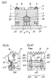
- the tube 23a shown in FIGS. 3 and 4 has tube sections 35a and 36a which are produced in the usual manner already described above and which are provided with transverse grooves 24a.
- a special profile section 37a is formed between the two sections 35a and 36a and has a polygonal cross section, in the present case a regular hexagonal cross section.
- the section 37a thus has a plurality of, in the specific case six, outer surfaces 39 which run parallel to the pipe axis 38 and thus to the production direction 4 and which in each case abut profile edges 40 and which therefore also run parallel to the pipe axis 38.
- the distance a between these profile edges 40 and the tube axis 38 is - based on the two outer surfaces 39 adjoining a profile edge 40, the maximum distance from the tube axis 38.
- a transition area 41a is formed between the area of the special profile section 37a delimited by the outer surfaces 39 and the adjacent sections 35a and 36a.
- a half mold 2a is shown, as it is used to form the tube sections 35a, 36a and the intermediate profile section 37a of a tube 23a. It has mold space sections 42a and 43a, which have mold recesses 27a corresponding to the cross section of the transverse grooves 24a.
- vacuum slots 44a are provided in a conventional manner, which are connected to the vacuum channels 28a and which each open into the region of the transverse grooves 24a, which is the radially outermost region with respect to the tube axis 38, in these. This can be seen in particular from FIG. 5.
- the pipe axis 38 corresponds to the mold space axis 45.
- the vacuum slots 44a run - as can be seen in FIG. 5 - transversely, that is to say at a right angle, to the direction of the mold space axis 45.
- a mold space section 46a is formed, which is used to mold the special profile section 37a. It has mold walls 47 which are used to shape the outer surfaces 39. At the abutting edges 48 or in the immediate vicinity of two such adjacent mold walls 47, vacuum slots 49a open into the mold space section 46a, which are also connected to at least one vacuum channel 28a. These vacuum slots 49a therefore run parallel to the profile edges 40 to be produced, ie parallel to the mold space axis 45, as the course of the vacuum slots 49a in FIG. 5 shows, these are cut into the half mold 2a with a disk milling cutter.
- the radial distance a of the vacuum slots 49 from the mold space axis 45 is therefore the greatest radial distance that a region of the mold wall 47 has from the mold space axis 45. A good, uniform, clean shape of the special profile section 37a is thus ensured.
- Separate vacuum slots are not always provided in the mold space sections 50a provided for shaping the transition regions 41a. In this exemplary embodiment, the evacuation takes place via the vacuum slots 49a, since these are also located radially outermost in relation to these mold space sections 50a - in relation to the mold space axis 45.
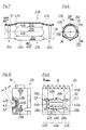
- a tube 23b is shown, which is partially formed in a half mold 2b according to FIGS. 9 and 10. It has pipe sections 35b and 36b, between which a special profile section 37b is formed, each of which merges into the pipe section 35b and 36b by means of a transition region 41b.
- the pipe sections 35b and 36b are basically smooth-walled, that is to say they have a profile that can be calibrated, as could also be produced, for example, by extrusion. They each have a constriction 51 which is approximately semicircular in cross section just before the transition region 41b. The constrictions 51 run transversely, that is to say perpendicularly, to the tube axis 38.
- the special profile section 37b is of identical design to the special profile section 37a in the exemplary embodiment according to FIGS. 3 and 4. For this reason, they will be described without further description Parts used the same reference numerals with the addition of ab.
- the mold space section 46b used to form the special profile section 37b is identical to the mold space section 46a according to FIGS. 5 and 6. 8 and 9, the same parts are therefore designated with the same reference number, which is supplemented by ab, without the need for a new description.
- the distance b between the mold space axis 45 and the abutting edge 48b what has been said above about the distance a applies.
- FIGS. 11 and 12 show the section of a tube 23c which is of identical design over its entire length, that is to say which has a special profile section throughout. It has transverse grooves 24c which only extend in sections in the circumferential direction. Are between the transverse grooves 24c 12 in the longitudinal direction of the tube 23c and parallel to the tube axis 38, in cross-section according to FIG. 12, approximately rectangular, that is to say altogether approximately cuboid, continuous elevations 57 are formed. These elevations 57 each have two side surfaces 58, which run approximately parallel to a radius to the pipe axis 38, and an outer surface 59, which runs transversely thereto and transversely to the pipe axis 38.
- outer surfaces 59 protrude radially slightly beyond the transverse grooves 24c, so that the outer surfaces 59 of a plurality of tubes 23c can be placed against one another on these outer surfaces 59 and stacked with their tube axes 38 arranged in parallel.
- channels are formed between the abutting elevations 57, that is to say in the region of the transverse grooves 24c. The use of such tubes 23c is thus conceivable for heat exchangers, in the same way as that according to FIGS. 3, 4 and 7,8.
- a half mold 2c which can be used to produce the tube 23c according to FIGS. 11 and 12 has suitable recesses 27c for producing the transverse grooves 24c, which are connected to vacuum channels 28c via vacuum slots 44c.
- these vacuum slots 44c extend over the full semi-cylindrical circumference of the molding space 26c of the half mold 2c. They run transversely to the mold space axis 45.
- the half mold 2c is further provided with recesses 60 which serve to form the elevations 57 and which have corresponding side walls 61 for forming the side surfaces 58 and an outer wall 62 for forming the outer surface 59.
- the radial distance c from the mold space axis 45 to a vacuum slot 49c is the greatest possible radial distance based on the respective distance between the adjacent regions of the side walls 61 and the outer wall 62 from the mold space axis 45, so that this is used to form the side surfaces 58 and the outer surface 59 of an elevation 57, the necessary vacuum is applied at the radially outermost point in relation to the mold space axis 45.
- the pipe 23d shown in FIGS. 15 and 16 has purely cylindrical pipe sections 35d and 36d, between which a special profile section 37d is arranged. It has a cylindrical region which is identical to that of the tube sections 35d and 36d. From this, an elevation 64 rises radially outwards, which is delimited by side surfaces 65 and an outer surface 66, in a manner similar to the elevation 57 of the exemplary embodiment according to FIGS. 11 and 12, with only this elevation 64 being located only over a certain special profile section 37d extends parallel to the tube axis 38.
- the one shown in FIGS. 17 and 18, used to manufacture the tube according to FIGS. 15 and 16 Half mold 2d has a substantially cylindrical mold recess 27d, with mold space sections 42d and 43d enclosing a mold space section 46d between them.
- the mold space sections 42d and 43d are cylindrical.
- Vacuum slots 44d open into them and are connected to vacuum channels 28d.
- the vacuum slots 44d run - as is generally customary - transversely to the mold space axis 45.
- In the mold space section 46d there is formed a groove-like recess 67 which runs parallel to the mold space axis 45 and is adapted in cross section to the elevation 64. It has side walls 68 and an outer wall 69 for shaping the side surfaces 65 and the outer surface 66.
- a vacuum slot 49d opens into the recess 67. These vacuum slots 49d are in turn connected to a vacuum channel 28d. It also applies here that the radial distance d of the abutting edges 70 running parallel to the mold space axis 45 is the maximum radial distance of the outer wall 69 or side walls 68 from the mold space axis 45.
- the pipe 23e according to FIGS. 19 and 20 differs from the pipe 23d according to FIGS. 15 and 16 only in that an elevation 71 is provided which differs from the elevation 64. Therefore, all reference numerals from FIGS. 15, 16, to which an e has been added, are otherwise used without the need for a new description.
- the elevation 71 has a side surface 72 running parallel to the pipe axis 38 and a side surface 73 running at an acute angle k to the pipe axis 38. To the outside is that Elevation 71 is completed by an outer surface 74.
- the angle k is in any case less than 30 ° and preferably 10 to 20 °.
- FIGS. 21, 22 The half mold which can be used to produce the tube 23e according to FIGS. 19, 20 is shown in FIGS. 21, 22.
- the same reference numerals are used as in FIGS. 17, 18, which are followed by an e.
- a recess 75 is provided which extends radially away from the mold recess 27e and has two side walls 76, 77 for forming the side surfaces 72, 73 and an outer wall 78 for forming the outer surface 74.
- the two side walls 76, 77 which meet at an acute angle at the angle k are still connected to one another by a short transverse wall 79 which runs transversely to the mold space axis 45 and serves to form a corresponding transverse surface 80 connecting the side surfaces 72, 73.
- a vacuum slot 49e is formed on the abutting edge 81 between the side wall 76 and the outer wall 78 of the recess 75 and is connected in a conventional manner to a vacuum channel 28e. This vacuum slot 49e extends parallel to the mold space axis 45.
- a vacuum slot 83 is formed on the abutting edge 82 between the side wall 77 and the outer wall 78, which also forms the angle k with the vacuum slot 49e and which is also connected to the vacuum channel 28e, as in particular 22 emerges.
- a vacuum slot 85 is also formed on the abutting edge 84 between the transverse wall 79 and the outer wall 78, which therefore runs transversely to the mold space axis 45 and which also is connected to its own vacuum channel 28e.
- the distance e of the abutting edges 81, 82, 84 and thus the distance of the vacuum slots 49e, 83, 85 from the mold space axis 45 is the relatively largest distance of the recess 75 from the mold space axis 45.
- FIGS. 23 and 24 largely corresponds to that according to FIGS. 9 and 10.
- the same reference numbers are therefore used without further description, to which an f is added.
- the tube which is produced using the half mold 2f according to FIGS. 23 and 24 is identical to that according to FIGS. 7 and 8, so that it does not need to be shown again in the drawing.
- the only difference with the half mold 2f compared to the half mold 2b is that the vacuum slots 49f do not extend over the full length of the mold space section 46f, but only over a central section, as can be seen in FIG. 23.
- This central vacuum slot 49f is followed by additional vacuum slots 86, 87 to form space section 50f, each of which is connected to its own vacuum channel 28f and is not connected to vacuum slot 49f.
- These vacuum slots 49f and 86, 87 likewise run parallel to the molding space axis 45. This separation of the vacuum slots running parallel to the molding space axis 45 and arranged one behind the other in the production direction 4 leads to an improvement in the
Description
Die Erfindung betrifft eine Vorrichtung zur Herstellung von Kunststoff-Rohren, bei der mit einer Formausnehmung versehene sich auf einer Formstrecke jeweils paarweise zu einer Form mit einer Formraumachse ergänzende Halbkokillen auf einem Maschinentisch im Kreislauf geführt angeordnet sind, wobei mindestens zwei sich zu einem Paar ergänzende Halbkokillen einen Formraum-Abschnitt zur Herstellung eines Sonderprofil-Abschnitts des Rohres aufweisen, wobei der Formstrecke ein Spritzkopf eines Extruders vorgeordnet ist, wobei die Halbkokillen mit mit der jeweiligen Formausnehmung verbundenen Vakuumkanälen versehen sind, die in der Formstrecke in im Maschinentisch ausgebildete Vakuumanschlüsse einmünden und die über Vakuumschlitze in die Formausnehmung einmünden.The invention relates to a device for the production of plastic pipes, in which half molds, which are provided with a mold recess on a molding section and are paired with a mold with a mold space axis, are arranged in a circuit on a machine table, at least two half molds complementing one another have a mold space section for producing a special profile section of the tube, the molding section being preceded by a spray head of an extruder, the half molds being provided with vacuum channels connected to the respective mold recess, which open into the vacuum section formed in the machine table and which over Open the vacuum slots in the mold recess.
Eine derartige Vorrichtung ist aus der DE-PS 12 55 292 bekannt. Auf derartigen Vorrichtungen können mit Querrillen, und zwar kreisförmig angeordneten Querrillen, versehene Rohre, sogenannte Wellrohre, hergestellt werden, wie in der EP-A1-0 065 729 (entsprechend US 4 492 551) beschrieben ist. Weiterhin können mit schraubenlinienförmig verlaufenden Querrillen versehene Wellrohre hergestellt werden, wie in der DE-PS 12 42 848 dargestellt ist. Anstelle der Querrillen können Rippen vorgesehen sein, wie der DE-PS 37 01 822 entnehmbar ist. Das Ausformen der Querrillen oder Rippen erfolgt im Vakuumverfahren, d.h. über mit Vakuum beaufschlagte Vakuumschlitze, die zumindest ganz überwiegend quer zur Richtung der Formraumachse angeordnet sind. Wie aus der DE-PS 17 04 715 hervorgeht, können auf der Vorrichtung nach der DE-PS 12 55 292 auch Rohre mit biegsamen Abschnitten hergestellt werden. Weiterhin können die geschilderten Rohre als Verbundrohre mit einem zusätzlichen inneren Rohr ausgebildet sein.Such a device is known from DE-PS 12 55 292. Such devices can be used to produce tubes, so-called corrugated tubes, with transverse grooves, specifically circular grooves, as described in EP-A1-0 065 729 (corresponding to US 4,492,551). Furthermore, can be provided with helical transverse grooves Corrugated tubes are produced, as shown in
Wenn Rohre mit Sonderprofil-Abschnitten hergestellt werden sollen, die zumindest bereichsweise ein kalibrierfähiges Profil, d.h. ein Profil aufweisen, das auch in ortsfesten Extrudier-Werkzeugen hergestellt werden könnte, dann ist eine qualitativ ausreichend gute Herstellung mit einer Vorrichtung der gattungsgemäßen Art im Vakuumverfahren nicht möglich.If pipes with special profile sections are to be produced that have a calibratable profile, i.e. have a profile that could also be produced in stationary extrusion tools, then a sufficiently good quality production with a device of the generic type in a vacuum process is not possible.
Der Erfindung liegt daher die Aufgabe zugrunde, eine Vorrichtung der gattungsgemäßen Art so auszugestalten, daß auch Sonderprofil-Abschnitte mit zumindest teilweise kalibrierfähigen Profilen im Vakuumverfahren mit hoher Genauigkeit und hoher Qualität herstellbar sind.The invention is therefore based on the object of designing a device of the generic type in such a way that even special profile sections with profiles that can be at least partially calibrated can be produced in a vacuum process with high accuracy and high quality.
Diese Aufgabe wird erfindungsgemäß dadurch gelöst, daß der Formraum-Abschnitt mindestens teilweise in Richtung der Formraumachse orientierte Flächen aufweist und daß mindestens ein Vakuumschlitz im Bereich dieser Flächen zumindest überwiegend parallel zur Formraumachse verläuft und in dem - bezogen auf die Formraumachse - radial am weitesten von dieser entfernten Bereich in den Formraum einmündet. Hierdurch wird sichergestellt, daß das Sonderprofil unter Vakuum sauber und vollständig und qualitativ gut ausgeformt wird. Wenn von Vakuum die Rede ist, dann wird hierunter ein Luftdruck verstanden, der kleiner als Atmosphärendruck ist. Unter Flächen werden nicht zwingend ebene Flächen, sondern auch gekrümmte Flächen verstanden. Die Vakuumschlitze müssen nicht zwingend durchgehend ausgebildet sein; sie können auch durch in eine Richtung hintereinander angeordnete kurze Vakuumschlitze oder Lochreihen gebildet sein; entscheidend ist ihre Orientierung zumindest überwiegend parallel zur Formraumachse. Das erfindungsgemäß angestrebte Ziel wird naturgemäß auch noch erreicht, wenn der mindestens eine Vakuumschlitz in unmittelbarer Nähe des radial am weitesten von der Formraumachse entfernten Bereichs in den Formraum einmündet. Wenn genau definierte, einen relativen maximalen Abstand zur Formraumachse aufweisende Stoßkanten zwischen Flächen der jeweiligen Halbkokille vorhanden sind, dann mündet der jeweilige Vakuumschlitz nach Anspruch 2 in dieser Stoßkante. Durch die Weiterbildung nach Anspruch 3 kann die Vakuumbeaufschlagung noch verbessert werden mit der Folge, daß die Ausformung noch weiter verbessert wird.This object is achieved according to the invention in that the mold space section has surfaces oriented at least partially in the direction of the mold space axis and in that at least one vacuum slot in the area of these surfaces is at least predominantly parallel to the mold space axis runs and in the - in relation to the mold space axis - opens radially the most distant from this area into the mold space. This ensures that the special profile is vacuum-formed cleanly, completely and with good quality. When we talk about vacuum, we mean an air pressure that is less than atmospheric pressure. Surfaces are not necessarily flat surfaces, but also curved surfaces. The vacuum slots do not necessarily have to be continuous; they can also be formed by short vacuum slots or rows of holes arranged one behind the other in one direction; their orientation is decisive, at least predominantly parallel to the mold space axis. The aim aimed at according to the invention is naturally also achieved if the at least one vacuum slot opens into the molding space in the immediate vicinity of the region that is the furthest radially from the molding space axis. If there are precisely defined butting edges having a relative maximum distance from the mold space axis between surfaces of the respective half mold, then the respective vacuum slot opens into this butting edge. Through the development according to
Für bestimmte Geometrien der Sonderprofil-Abschnitte kann die Weiterbildung nach Anspruch 4 zweckmäßig sein.For certain geometries of the special profile sections, the development according to
Die Vakuumschlitze weisen in bekannter Weise eine Breite von kleiner oder gleich 0,5 mm auf um sicherzustellen, daß bei der Ausformung des Rohres der noch warmplastische Kunststoff nicht in die Vakuumschlitze hineingezogen wird. Durch die erfindungsgemäßen Maßnahmen wird primär lediglich sichergestellt, daß eine vollständige, flächige Anlage des noch warmplastischen Schlauches zur Erzeugung eines Rohres an den Flächen bzw. der Wand des entsprechenden Formraum-Abschnitts erreicht wird.In a known manner, the vacuum slots have a width of less than or equal to 0.5 mm to ensure that when the tube is formed, the still warm plastic is not drawn into the vacuum slots. The measures according to the invention primarily only ensure that a complete, flat contact of the still warm plastic hose for producing a tube is achieved on the surfaces or the wall of the corresponding mold space section.
Weitere Einzelheiten der Erfindung ergeben sich aus der nachfolgenden Beschreibung zahlreicher Ausführungsbeispiele anhand der Zeichnung. Es zeigt
- Fig. 1
- eine Draufsicht auf eine Vorrichtung nach der Erfindung,
- Fig. 2
- einen Vertikalschnitt durch ein Halbkokillenpaar der Vorrichtung,
- Fig. 3
- ein erstes Rohr mit einem Sonderprofil-Abschnitt in einer Teil-Schnitt-Darstellung entsprechend der Schnittlinie III-III in Fig. 4
- Fig. 4
- einen Querschnitt durch das erste Rohr gemäß der Schnittlinie IV-IV in Fig. 3,
- Fig. 5
- eine Halbkokille zur Herstellung des ersten Rohres in Seitenansicht,
- Fig. 6
- die Halbkokille nach Fig. 5 in Stirnansicht, teilweise aufgebrochen,
- Fig. 7
- ein zweites Rohr mit einem Sonderprofil-Abschnitt in einem Teilschnitt gemäß der Schnittlinie VII-VII in Fig. 8,
- Fig. 8
- einen Querschnitt durch das zweite Rohr gemäß der Schnittlinie VIII-VIII in Fig. 7,
- Fig. 9
- eine Halbkokille zur Herstellung des zweiten Rohres in Seitenansicht,
- Fig. 10
- die Halbkokille nach Fig. 9 in Stirnansicht in teilweise aufgebrochener Darstellung,
- Fig. 11
- ein drittes Rohr im Teil-Längs-Schnitt gemäß der Schnittlinie XI-XI in Fig. 12,
- Fig. 12
- das dritte Rohr im Querschnitt gemäß der Schnittlinie XII-XII in Fig. 11,
- Fig. 13
- eine Halbkokille zur Herstellung des dritten Rohres in Seitenansicht,
- Fig. 14
- die Halbkokille nach Fig. 13 in Stirnansicht in teilweise aufgebrochener Darstellung,
- Fig. 15
- ein viertes Rohr mit einem Sonderprofil-Abschnitt in einem Teil-Längs-Schnitt gemäß der Schnittlinie XV-XV in Fig. 16,
- Fig. 16
- einen Querschnitt durch das vierte Rohr gemäß der Schnittlinie XVI-XVI in Fig. 15,
- Fig. 17
- eine Halbkokille zur Herstellung des vierten Rohres in Seitenansicht,
- Fig. 18
- die Halbkokille nach Fig. 17 in Stirnansicht und teilweise aufgebrochener Darstellung,
- Fig. 19
- ein fünftes Rohr mit einem Sonderprofil-Abschnitt in teilweise aufgebrochener Darstellung,
- Fig. 20
- einen Querschnitt durch das fünfte Rohr gemäß der Schnittlinie XX-XX in Fig. 19,
- Fig. 21
- eine Halbkokille zur Herstellung des fünften Rohres in Seitenansicht,
- Fig. 22
- die Halbkokille nach Fig. 21 in Stirnansicht in teilweise aufgebrochener Darstellung,
- Fig. 23
- eine abgewandelte Ausführungsform einer Halbkokille zur Herstellung des zweiten Rohres in Seitenansicht und
- Fig. 24
- die Halbkokille nach Fig. 23 in Stirnansicht in teilweise aufgebrochener Darstellung.
- Fig. 1
- a plan view of a device according to the invention,
- Fig. 2
- a vertical section through a pair of half molds of the device,
- Fig. 3
- a first tube with a special profile section in a partial sectional view corresponding to the section line III-III in Fig. 4th
- Fig. 4
- 3 shows a cross section through the first tube along the section line IV-IV in FIG. 3,
- Fig. 5
- a half mold for the production of the first tube in side view,
- Fig. 6
- 5 in partial front view, partially broken away,
- Fig. 7
- a second tube with a special profile section in a partial section along the section line VII-VII in Fig. 8,
- Fig. 8
- FIG. 7 shows a cross section through the second tube according to section line VIII-VIII in FIG. 7,
- Fig. 9
- a half mold for the production of the second tube in side view,
- Fig. 10
- 9 is a partial view of the half mold according to FIG. 9 in front view,
- Fig. 11
- a third tube in partial longitudinal section along the section line XI-XI in Fig. 12,
- Fig. 12
- the third tube in cross section along the section line XII-XII in Fig. 11,
- Fig. 13
- a half mold for the production of the third tube in side view,
- Fig. 14
- 13 is a partial view of the half mold according to FIG. 13 in front view,
- Fig. 15
- a fourth tube with a special profile section in a partial longitudinal section along the section line XV-XV in Fig. 16,
- Fig. 16
- FIG. 15 shows a cross section through the fourth tube along the section line XVI-XVI in FIG. 15,
- Fig. 17
- a half mold for the production of the fourth tube in side view,
- Fig. 18
- 17 the half mold according to FIG. 17 in front view and partially broken away representation,
- Fig. 19
- a fifth tube with a special profile section, partly broken away,
- Fig. 20
- FIG. 19 shows a cross section through the fifth tube according to the section line XX-XX in FIG. 19,
- Fig. 21
- a half mold for the production of the fifth tube in side view,
- Fig. 22
- 21 the half mold according to FIG. 21 in front view in a partially broken open representation,
- Fig. 23
- a modified embodiment of a half mold for producing the second tube in side view and
- Fig. 24
- the half mold of FIG. 23 in front view in a partially broken representation.
Wie Fig. 1 erkennen läßt, weist eine Vorrichtung zur Herstellung von Kunststoffrohren mit Querrillen einen Maschinentisch 1 auf, auf dem Halbkokillen 2 bzw. 2' angeordnet sind, die jeweils zu zwei sogenannten Ketten 3 bzw. 3' miteinander verbunden sind. Hierzu ist an jeder Halbkokille 2 bzw. 2' in ihrem außenliegenden, in Produktionsrichtung 4 vorderen Bereich eine Lasche 5 mittels eines Anlenkbolzens 6 angelenkt, die an der entsprechenden Stelle der nachfolgenden Halbkokille 2 bzw. 2' ebenfalls mittels eines solchen Anlenkbolzens 6 angebracht ist. Die so gebildeten Ketten 3, 3' sind an ihrem in Produktionsrichtung 4 gesehen rückwärtigen Ende über als sogenannte Einlaufrollen 7 dienende Umlenkräder geführt. Die einzelnen Halbkokillen 2, 2' werden beim Umlauf der Ketten 3, 3' entsprechend den Umlaufrichtungspfeilen 8 bzw. 8' in eine Formstrecke 9 eingeschwenkt, in der jeweils zwei Halbkokillen 2, 2' zu einem Kokillenpaar vereinigt werden, wobei wiederum in Produktionsrichtung 4 hintereinanderfolgende Kokillenpaare dicht an dicht liegen. Um ein schnelles Schließen der Halbkokillen 2, 2' zu einer parallelen und aneinanderliegenden Stellung zu erreichen, sind sogenannte Schließrollen 10 vorgesehen, die die in Produktionsrichtung 4 hinteren Enden der Halbkokillen 2, 2' beschleunigt zusammenführen.As can be seen in FIG. 1, a device for producing plastic pipes with transverse grooves has a machine table 1, on which
In der Formstrecke 9 selber werden die aneinanderliegenden Halbkokillen 2, 2' mittels Führungsrollen 11, die in Führungsleisten 12 drehbar gelagert sind, gegeneinander gedrückt. Die Einlaufrollen 7 sind um Achszapfen 13 drehbar am Maschinentisch 1 angebracht. Am in Produktionsrichtung 4 vorderen Ende des Maschinentisches 1 sind ebenfalls als Umlenkräder dienende Rücklaufrollen 14 um Achszapfen 15 drehbar gelagert, um die die Ketten 3 bzw. 3' umgelenkt und zu den Einlaufrollen 7 zurückgeführt werden. Wie Fig. 1 zu entnehmen ist, enden die Führungsleisten 12 mit Führungsrollen 11 schon um die Länge mehrerer Halbkokillen 2 bzw. 2' vor den Rücklaufrollen 14, so daß die Halbkokillen 2 bzw. 2' wieder parallel zueinander und quer zur Produktionsrichtung 4 voneinander wegbewegt werden können, bevor sie von den Rücklaufrollen 14 verschwenkt werden.In the
An der Oberseite der Halbkokillen 2, 2' ist eine Verzahnung 16 ausgebildet, wobei die beiden Verzahnungen 16 der einander paarweise zugeordneten Halbkokillen 2, 2' miteinander fluchten, so daß von oben ein gemeinsames Antriebsritzel 17 in diese Verzahnung 16 eingreifen kann, das die Halbkokillen 2, 2' in der Formstrecke 9 als geschlossene Form durch die Formstrecke 9 schiebt. Der Antrieb dieses Antriebsritzels 17 erfolgt in üblicher Weise von einem nicht dargestellten Motor über ein Antriebszahnrad 18, das auf einer Welle 19 drehfest befestigt ist, die wiederum das Antriebsritzel 17 trägt. Die Welle 19 ist in einem Lagerbock 20 gelagert, der über Distanzprismen 21 gegenüber dem Maschinentisch abgestützt und mit letzterem mittels Schrauben 22 fest verbunden ist.On the top of the
Auf der dargestellten Vorrichtung werden Kunststoff-Rohre 23 mit u.a. einer Querprofilierung, d.h. mit über deren Umfang umlaufenden Rillen 24 hergestellt.On the device shown,
Die Rohre 23 werden weiter unten noch genauer beschrieben. Hierzu ist ein Extruder vorgesehen, von dem nur der Spritzkopf 25 angedeutet ist, aus dem ein nicht sichtbarer Schlauch extrudiert wird, der in noch warmplastischem Zustand in die in der Formstrecke 9 gebildete Form einläuft, in der unter anderem die Querprofilierung ausgebildet wird. Die bisher beschriebene Vorrichtung ist bekannt, und zwar beispielsweise aus der EP-A-0 065 729. Mit dieser Vorrichtung können in gleicher Weise sogenannte Verbundrohre hergestellt werden die äußerlich dem Rohr 23 gleichen und innen noch mit einem durchgehend glatten Rohr einstückig ausgebildet sind.The
In der Formstrecke 9 erfolgt u.a. die Ausformung der Rillen 24 durch Vakuumbeaufschlagung des in der Formstrecke 9 gebildeten Formraums 26. Die in den Halbkokillen 2, 2' zur Bildung eines Formraums 26 ausgeformten Formausnehmungen 27, 27' haben eine zu der Außenform des Rohres 23 komplementäre Form. Sie sind mit Vakuumkanälen 28, 28' versehen, die in der Nähe der Wand der Formausnehmung 27 bzw. 27' verlaufen und diese bei paarweise aneinanderliegenden Halbkokillen 2, 2' in verhältnismäßig geringem Abstand umschließen. Von den Vakuumkanälen 28, 28' münden zahlreiche, weiter unten noch zu beschreibende Vakuumschlitze in die Formausnehmung 27 bzw. 27'. Die Vakuumkanäle 28, 28' sind bei aneinanderliegenden Halbkokillen 2, 2' miteinander verbunden, wie aus Fig. 2 hervorgeht. Die Vakuumkanäle 28 bzw. 28' münden in die auf dem Maschinentisch 1 aufliegende Unterseite 29 bzw. 29' der Halbkokillen 2, 2'. Bei paarweise aneinanderliegenden Halbkokillen 2, 2' sind sie in Überdeckung mit im Maschinentisch 1 angebrachten Vakuumanschlüssen 30, 30', die wiederum an eine Vakuumpumpe angeschlossen sind. Die Luftströmung in den Vakuumkanälen 28, 28' und an den Vakuumanschlüssen 30, 30' ist durch Richtungspfeile 31 gekennzeichnet.In the
In den nachfolgenden Beispielen werden jeweils Rohre dargestellt und beschrieben, die streckenweise oder durchgängig Sonderprofil-Abschnitte aufweisen. Die zur Herstellung erforderlichen Halbkokillen werden hierzu ebenfalls dargestellt.The following examples show and describe pipes that have sections or sections of special profiles. The half molds required for production are also shown.
Das in den Figuren 3 und 4 dargestellte Rohr 23a weist in üblicher, oben bereits beschriebener Weise hergestellte Rohr-Abschnitte 35a und 36a auf, die mit Querrillen 24a versehen sind. Zwischen den beiden Abschnitten 35a und 36a ist ein Sonderprofil-Abschnitt 37a ausgebildet, der einen Mehrkant-Querschnitt, im vorliegenden Fall einen regelmäßigen Sechskant-Querschnitt aufweist. Der Abschnitt 37a weist also mehrere, im konkreten Fall sechs, parallel zur Rohrachse 38 und damit zur Produktionsrichtung 4 verlaufende Außenflächen 39 auf, die sich jeweils an Profilkanten 40 stoßen, die also auch parallel zur Rohrachse 38 verlaufen. Der Abstand a dieser Profil-Kanten 40 und der Rohrachse 38 ist - bezogen auf die beiden sich an jeweils eine Profil-Kante 40 anschließenden Außenflächen 39 der maximale Abstand von der Rohrachse 38. Mit anderen Worten heißt dies, daß die Außenflächen 39 jeweils an ihren Profilkanten 40 einen maximalen Abstand a zur Rohrachse 38 aufweisen und daß der jeweils zwischen den beiden eine Außenfläche 39 begrenzenden Profil-Kanten 40 liegende Bereich einer Außenfläche 39 einen radialen Abstand von der Rohrachse 38 hat, der kleiner ist als a. Zwischen dem durch die Außenflächen 39 begrenzten Bereich des Sonderprofil-Abschnitts 37a und den benachbarten Abschnitten 35a und 36a ist jeweils ein Übergangsbereich 41a ausgebildet.The
In den Fig. 5 und 6 ist eine Halbkokille 2a dargestellt, wie sie zur Ausformung der Rohrabschnitte 35a, 36a und des dazwischen liegenden Sonderprofil-Abschnittes 37a eines Rohres 23a eingesetzt wird. Sie weist Formraum-Abschnitte 42a und 43a auf, die den Querschnitt der Querrillen 24a entsprechende Formausnehmungen 27a aufweisen. Um die Ausformung der Querrillen 24a sicherzustellen, sind in üblicher Weise Vakuumschlitze 44a vorgesehen, die mit den Vakuumkanälen 28a verbunden sind und die jeweils im - bezogen auf die Rohrachse 38 - radial am weitesten außenliegenden Bereich der Querrillen 24a in diese einmünden. Dies ist insbesondere aus Fig. 5 erkennbar.5 and 6, a
Die Rohrachse 38 entspricht der Formraumachse 45. Die Vakuumschlitze 44a verlaufen - wie Fig. 5 erkennen läßt - quer, also unter einem rechten Winkel, zur Richtung der Formraumachse 45.The
Zwischen den beiden Formraum-Abschnitten 42a, 43a, ist ein Formraum-Abschnitt 46a ausgebildet, der zur Ausformung des Sonderprofil-Abschnittes 37a dient. Er weist Formwände 47 auf, die zur Ausformung der Außenflächen 39 dienen. An den Stoßkanten 48 oder in unmittelbarer Nähe zweier solcher benachbarter Formwände 47 münden Vakuumschlitze 49a in den Formraum-Abschnitt 46a, die ebenfalls mit mindestens einem Vakuumkanal 28a verbunden sind. Diese Vakuumschlitze 49a verlaufen also parallel zu den zu erzeugenden Profil-Kanten 40, d.h. parallel zur Formraumachse 45, wie der Verlauf der Vakuumschlitze 49a in Fig. 5 zeigt, werden diese mit einem Scheibenfräser in die Halbkokille 2a geschnitten. Der radiale Abstand a der Vakuumschlitze 49 von der Formraumachse 45 ist also der größte radiale Abstand, den ein Bereich der Formwand 47 von der Formraumachse 45 hat. Eine gute gleichmäßige saubere Ausformung des Sonder-Profilabschnittes 37a ist also gewährleistet. In den zur Ausformung der Übergangsbereiche 41a vorgesehenen Formraum-Abschnitten 50a sind nicht immer gesonderte Vakuumschlitze vorgesehen. Die Evakuierung erfolgt in diesem Ausführungsbeispiel über die Vakuumschlitze 49a, da diese auch relativ zu diesen Formraum-Abschnitten 50a - bezogen auf die Formraumachse 45 - radial am weitesten außen liegen.Between the two
In den Fig. 7 und 8 ist ein Rohr 23b dargestellt, das bereichsweise in einer Halbkokille 2b nach den Fig. 9 und 10 ausgeformt wird. Es weist Rohr-Abschnitte 35b und 36b auf, zwischen denen ein Sonderprofil-Abschnitt 37b ausgeformt ist, der jeweils mittels eines Übergangsbereichs 41b in den Rohr-Abschnitt 35b bzw. 36b übergeht.7 and 8, a
Die Rohr-Abschnitte 35b und 36b sind im Grundsatz glattwandig ausgebildet, haben also ein kalibrierfähiges Profil, wie es beispielsweise auch durch Extrudieren hergestellt werden könnte. Sie weisen jeweils kurz vor dem Übergangsbereich 41b eine im Querschnitt etwa halbkreisförmige Einschnürung 51 auf. Die Einschnürungen 51 verlaufen quer, also senkrecht, zur Rohrachse 38. Der Sonderprofil-Abschnitt 37b ist identisch ausgebildet wie der Sonderprofil-Abschnitt 37a im Ausführungsbeispiel nach den Fig. 3 und 4. Es werden deshalb ohne weitere Beschreibung für dieselben Teile dieselben Bezugsziffern unter Hinzufügung eines b verwendet. Die in den Fig. 9 und 10 dargestellte Halbkokille 2b, die zur Ausformung des in den Fig. 7 und 8 dargestellten Abschnitts des Rohres 23b dient, weist Formraum-Abschnitte 42b und 43b auf, die zur Herstellung der Rohr-Abschnitt 35b und 36b dienen. Sie weisen lediglich einen der jeweiligen Einschnürung 51 entsprechenden Formwulst 52 auf, der zur Ausformung der Einschnürung 51 dient. Beiderseits des Formwulstes 52, also am Übergang zur sich anschließenden glatten Formwand sind Vakuumschlitze 44b ausgebildet, die mit den Vakuumkanälen 28b jeweils verbunden sind. Sie befinden sich also in einem Bereich, der den - bezogen auf die benachbarten Bereiche - maximalen Abstand zur Formraumachse 45 aufweist.The
Der zur Ausformung des Sonderprofil-Abschnittes 37b dienende Formraum-Abschnitt 46b ist identisch zu dem Formraum-Abschnitt 46a nach Fig. 5 und 6 ausgebildet. Es werden daher in den Fig. 8 und 9 dieselben Teile mit derselben Bezugsziffer bezeichnet, die um ein b ergänzt ist, ohne daß es einer erneuten Beschreibung bedarf. Für den Abstand b zwischen der Formraumachse 45 und der Stoßkante 48b gilt das oben zum Abstand a Gesagte.The mold space section 46b used to form the
In den Fig. 11 und 12 ist der Abschnitt eines Rohres 23c abgebildet, das über seine ganze Länge gleich ausgebildet ist, das also durchgängig einen Sonderprofil-Abschnitt aufweist. Es weist Querrillen 24c auf, die sich in Umfangsrichtung jeweils nur abschnittsweise erstrecken. Zwischen den Querrillen 24c sind sich in Längsrichtung des Rohres 23c und parallel zur Rohrachse 38 erstreckende im Querschnitt gemäß Fig. 12 etwa rechteckige, insgesamt also etwa quaderförmige, ununterbrochene Erhebungen 57 ausgeformt. Diese Erhebungen 57 weisen jeweils zwei Seitenflächen 58, die etwa parallel zu einem Radius zur Rohrachse 38 verlaufen, und eine Außenfläche 59 auf, die quer hierzu und quer zur Rohrachse 38 verläuft. Diese Außenflächen 59 ragen radial geringfügig über die Querrillen 24c vor, so daß die Außenflächen 59 mehrerer Rohre 23c an diesen Außenflächen 59 aneinandergelegt und unter paralleler Anordnung ihrer Rohrachsen 38 gestapelt werden können. Hierbei werden zwischen den aneinanderliegenden Erhebungen 57, also im Bereich der Querrillen 24c, Kanäle gebildet. Der Einsatz solcher Rohre 23c ist also - gleichermaßen wie der nach den Fig. 3, 4 und 7,8 - für Wärmeübertrager denkbar.FIGS. 11 and 12 show the section of a
Eine zur Herstellung des Rohres 23c nach den Fig. 11 und 12 einsetzbare Halbkokille 2c weist zur Herstellung der Querrillen 24c geeignete Formausnehmungen 27c auf, die über Vakuumschlitze 44c mit Vakuumkanälen 28c verbunden sind. Diese Vakuumschlitze 44c erstrecken sich in diesem Fall über den vollen halbzylindrischen Umfang des Formraums 26c der Halbkokille 2c. Sie verlaufen quer zur Formraumachse 45. Die Halbkokille 2c ist weiterhin mit zur Ausformung der Erhebungen 57 dienenden Ausnehmungen 60 versehen, die zur Ausformung der Seitenflächen 58 entsprechende Seitenwände 61 und zur Ausformung der Außenfläche 59 jeweils eine Außenwand 62 aufweisen. An den Stoßkanten 63 zwischen jeweils einer Seitenwand 61 und einer Außenwand 62 sind einzelne Vakuumschlitze 49c ausgebildet, die also parallel zur Formraumachse 45 verlaufen. Sie sind direkt an die Vakuumschlitze 44c angeschlossen und über diese jeweils mit einem Vakuumkanal 28c verbunden. Die fortlaufend hintereinander angeordneten Vakuumschlitze 49c, die einer Stoßkante 63 zugeordnet sind, sind also nicht miteinander verbunden. Auch hier gilt, daß der radiale Abstand c von der Formraumachse 45 zu einem Vakuumschlitz 49c bezogen auf den jeweiligen Abstand der benachbarten Bereiche der Seitenwände 61 bzw. der Außenwand 62 von der Formraumachse 45 der größtmögliche radiale Abstand ist, so daß das zur Ausformung der Seitenflächen 58 und der Außenfläche 59 einer Erhebung 57 notwendige Vakuum an der - bezogen auf die Formraumachse 45 - radial am weitesten außenliegenden Stelle aufgebracht wird.A half mold 2c which can be used to produce the
Das in den Fig. 15 und 16 dargestellte Rohr 23d weist rein zylindrische Rohr-Abschnitte 35d und 36d auf, zwischen denen ein Sonderprofil-Abschnitt 37d angeordnet ist. Er weist einen zylindrischen Bereich auf, der mit dem der Rohr-Abschnitte 35d und 36d identisch ist. Hieraus erhebt sich eine Erhebung 64 radial nach außen, die von Seitenflächen 65 und einer Außenfläche 66 begrenzt ist und zwar ähnlich wie die Erhebung 57 des Ausführungsbeispiels nach den Fig. 11 und 12, wobei lediglich diese Erhebung 64 sich nur über einen gewissen Sonderprofil-Abschnitt 37d parallel zur Rohrachse 38 erstreckt.The
Die in den Fig. 17 und 18 dargestellte, zur Herstellung des Rohres nach den Fig. 15 und 16 eingesetzte Halbkokille 2d weist eine im wesentlichen zylindrische Formausnehmung 27d auf, wobei Formraum-Abschnitte 42d und 43d zwischen sich einen Formraum-Abschnitt 46d einschließen. Die Formraum-Abschnitte 42d und 43d sind zylindrisch ausgebildet. In sie münden Vakuumschlitze 44d ein, die mit Vakuumkanälen 28d verbunden sind. Die Vakuumschlitze 44d verlaufen - wie allgemein üblich - quer zur Formraumachse 45. Im Formraum-Abschnitt 46d ist eine parallel zur Formraumachse 45 verlaufende nutartige Ausnehmung 67 ausgebildet, die im Querschnitt der Erhebung 64 angepaßt ist. Sie weist Seitenwände 68 und eine Außenwand 69 zur Ausformung der Seitenflächen 65 bzw. der Außenfläche 66 auf. An der Stoßkante 70 zwischen einer Seitenwand 68 und der Außenwand 69 mündet jeweils ein Vakuumschlitz 49d in die Ausnehmung 67 ein. Diese Vakuumschlitze 49d sind wiederum mit einem Vakuumkanal 28d verbunden. Auch hier gilt, daß der radiale Abstand d der parallel zur Formraumachse 45 verlaufenden Stoßkanten 70 der maximale radiale Abstand der Außenwand 69 bzw. Seitenwände 68 von der Formraumachse 45 ist.The one shown in FIGS. 17 and 18, used to manufacture the tube according to FIGS. 15 and 16
Das Rohr 23e nach den Fig. 19 und 20 unterscheidet sich von dem Rohr 23d nach den Fig. 15 und 16 nur dadurch, daß eine Erhebung 71 vorgesehen ist, die sich von der Erhebung 64 unterscheidet. Daher sind ansonsten alle Bezugsziffern aus den Fig. 15, 16 verwendet, denen ein e hinzugefügt ist, ohne daß es einer erneuten Beschreibung bedarf. Die Erhebung 71 weist ein parallel zur Rohrachse 38 verlaufende Seitenfläche 72 und eine unter einem spitzen Winkel k zur Rohrachse 38 verlaufende Seitenfläche 73 auf. Nach außen ist die Erhebung 71 durch eine Außenfläche 74 abgeschlossen. Der Winkel k ist auf jeden Fall kleiner als 30° und zwar bevorzugt 10 bis 20°.The
Die zur Herstellung des Rohres 23e nach den Fig. 19, 20 einsetzbare Halbkokille ist in den Fig. 21, 22 dargestellt. Es werden weitgehend dieselben Bezugsziffern wie in den Fig. 17, 18 verwendet, denen jeweils ein e nachgestellt ist. Zur Herstellung der Erhebung 71 ist eine sich radial von der Formausnehmung 27e weg erstreckende Ausnehmung 75 vorgesehen, die zwei Seitenwände 76, 77 zur Ausformung der Seitenflächen 72, 73 und eine Außenwand 78 zur Ausformung der Außenfläche 74 aufweist. Die beiden spitzwinklig unter dem Winkel k zusammentreffenden Seitenwände 76, 77 sind noch durch eine kurze, quer zur Formraumachse 45 verlaufende Querwand 79 miteinander verbunden, die zur Ausformung einer entsprechenden, die Seitenflächen 72, 73 verbindenden Querfläche 80 dient. An der Stoßkante 81 zwischen der Seitenwand 76 und der Außenwand 78 der Ausnehmung 75 ist ein Vakuumschlitz 49e ausgebildet, der in üblicher Weise an einen Vakuumkanal 28e angeschlossen ist. Dieser Vakuumschlitz 49e erstreckt sich parallel zur Formraumachse 45. An der Stoßkante 82 zwischen der Seitenwand 77 und der Außenwand 78 ist ein Vakuumschlitz 83 ausgebildet, der mit dem Vakuumschlitz 49e ebenfalls den Winkel k einschließt und der ebenfalls an den Vakuumkanal 28e angeschlossen ist, wie insbesondere aus Fig. 22 hervorgeht. An der Stoßkante 84 zwischen der Querwand 79 und der Außenwand 78 ist noch ein Vakuumschlitz 85 ausgebildet, der also quer zur Formraumachse 45 verläuft und der ebenfalls an einen eigenen Vakuumkanal 28e angeschlossen ist. Auch hier gilt, daß der Abstand e der Stoßkanten 81, 82, 84 und damit der Abstand der Vakuumschlitze 49e, 83, 85 von der Formraumachse 45 der relativ größte Abstand der Ausnehmung 75 von der Formraumachse 45 ist.The half mold which can be used to produce the
Das Ausführungsbeispiel nach den Fig. 23 und 24 entspricht weitgehend dem nach den Fig. 9 und 10. Es sind daher ohne weitere Beschreibung dieselben Bezugsziffern verwendet, denen ein f hinzugefügt ist. Das Rohr, das unter Verwendung der Halbkokille 2f nach den Fig. 23 und 24 hergestellt wird, ist identisch dem nach den Fig. 7 und 8, so daß es keiner erneuten zeichnerischen Darstellung bedarf. Unterschiedlich an der Halbkokille 2f im Vergleich zu der Halbkokille 2b ist lediglich, daß die Vakuumschlitze 49f sich nicht über die volle Länge des Formraum-Abschnitts 46f erstrecken, sondern lediglich über einen mittleren Teilabschnitt, wie Fig. 23 entnehmbar ist. An diesen mittleren Vakuumschlitz 49f schließen sich zum Formraum-Abschnitt 50f jeweils zusätzliche Vakuumschlitze 86, 87 an, die jeweils an einen eigenen Vakuumkanal 28f angeschlossen sind und die nicht in Verbindung mit dem Vakuumschlitz 49f stehen. Diese Vakuumschlitze 49f und 86, 87 verlaufen ebenfalls parallel zur Formraumachse 45. Diese Trennung der parallel zur Formraumachse 45 verlaufenden und in Produktionsrichtung 4 hintereinander angeordneten Vakuumschlitze führt zu einer Verbesserung der Ausformung.The embodiment according to FIGS. 23 and 24 largely corresponds to that according to FIGS. 9 and 10. The same reference numbers are therefore used without further description, to which an f is added. The tube which is produced using the
Claims (4)
- An apparatus for the production of plastic pipes (23) having half shells (2), which are provided with a mold recess (27) and of which two in each case combine on a molding path (9) to form a mold with a mold space axis (45), arranged on a machine bed (1) to be be circuit guided, two half shells (2, 2') that combine to form a pair having a mold space section (46) for the production of a special profile section (37) of the pipe (23), a head (25) of an extruder being arranged upstream of the molding path (9), the half shells (2) being provided with vacuum channels (28) connected with each mold recess (27) by way of vacuum slits (44) and vacuum connections (30) being provided in the machine bed (1) and opening into the molding path (9) where they run into the vacuum channels (28), characterized in that the mold space section (46) has surfaces oriented at least partially in the direction of the mold space axis (45) and in that in the area of these surfaces at least one vacuum slit (49) extends at least substantially parallel to the mold space axis (45) and opens into the mold space (27) in the portion which - in relation to the mold space axis (45) - is radially the most distant from it.
- An apparatus according to claim 1, characterized in that the surfaces adjoin forming at least one joint edge (48) and in that a vacuum slit (49) opens into the mold space (27) in the joint edge (48).
- An apparatus according to claim 1, characterized in that a plurality of vacuum slits (49) not connected with each other open one behind the other into the mold space (27) in the direction of the mold space axis (45).
- An apparatus according to claim 1, characterized in that at least on vacuum slit (44) is provided extending at right angles to the mold space axis (45) and in that at least one vacuum slit (49) extending approximately parallel to the mold space axis (45) is connected with the vacuum slit (44) extending at right angles to the mold space axis (45).
Applications Claiming Priority (2)
| Application Number | Priority Date | Filing Date | Title |
|---|---|---|---|
| DE4021564A DE4021564A1 (en) | 1990-07-06 | 1990-07-06 | DEVICE FOR PRODUCING PLASTIC TUBES |
| DE4021564 | 1990-07-06 |
Publications (2)
| Publication Number | Publication Date |
|---|---|
| EP0464411A1 EP0464411A1 (en) | 1992-01-08 |
| EP0464411B1 true EP0464411B1 (en) | 1994-08-24 |
Family
ID=6409790
Family Applications (1)
| Application Number | Title | Priority Date | Filing Date |
|---|---|---|---|
| EP91109580A Expired - Lifetime EP0464411B1 (en) | 1990-07-06 | 1991-06-11 | Apparatus for the manufacture of plastic pipes |
Country Status (6)
| Country | Link |
|---|---|
| US (1) | US5141427A (en) |
| EP (1) | EP0464411B1 (en) |
| JP (1) | JP3016628B2 (en) |
| CA (1) | CA2045354C (en) |
| DE (2) | DE4021564A1 (en) |
| ES (1) | ES2060247T3 (en) |
Families Citing this family (12)
| Publication number | Priority date | Publication date | Assignee | Title |
|---|---|---|---|---|
| DE4111228A1 (en) * | 1991-04-08 | 1992-10-15 | Wilhelm Hegler | DEVICE FOR PRODUCING PLASTIC TUBES |
| DE4210482A1 (en) * | 1992-03-31 | 1993-10-07 | Wilhelm Hegler | Method and device for the continuous production of a composite pipe with a pipe socket |
| GB9212684D0 (en) * | 1992-06-15 | 1992-07-29 | Lupke Manfred Arno Alfred | A method and apparatus for forming profiled tubes |
| US5460771A (en) * | 1992-10-16 | 1995-10-24 | Itt Corporation | Process for producing corrugated multi-layer tubing having layers of differing plastic characteristics |
| FR2748417B1 (en) * | 1996-05-09 | 1998-06-12 | Corelco | PLANT FOR THE MANUFACTURE BY LOW PRESSURE OF TUBULAR BODIES OF SYNTHETIC MATERIAL |
| DE19702647C1 (en) * | 1997-01-25 | 1998-02-26 | Unicor Rohrsysteme Gmbh | Corrugated tubing moulding unit having jaws with vacuum and coolant connections |
| ATE203950T1 (en) * | 1997-10-15 | 2001-08-15 | Corelco | DEVICE FOR PRODUCING TUBE-LIKE PLASTIC OBJECTS USING VACUUM |
| US5960977A (en) * | 1998-05-14 | 1999-10-05 | Itt Manufacturing Enterprises, Inc. | Corrugated polymeric filler neck tubing |
| US6240970B1 (en) | 1999-04-01 | 2001-06-05 | Itt Manufacturing Enterprises, Inc. | Tubing for handling hydrocarbon materials and having an outer jacket layer adhered thereto |
| DE19916641C2 (en) * | 1999-04-14 | 2002-09-05 | Unicor Rohrsysteme Gmbh | Device for producing a corrugated tube that can be opened and reclosed in its longitudinal direction |
| US6276400B1 (en) | 1999-06-08 | 2001-08-21 | Itt Manufacturing Enterprises, Inc. | Corrosion resistant powder coated metal tube and process for making the same |
| DE102015115828A1 (en) * | 2015-09-18 | 2017-03-23 | Unicor Gmbh | Device for producing plastic pipes |
Family Cites Families (13)
| Publication number | Priority date | Publication date | Assignee | Title |
|---|---|---|---|---|
| DE1255292B (en) * | 1962-08-16 | 1967-11-30 | Wilhelm Hegler Isolierrohrwerk | Device for deforming a pipe made of plastic |
| DE1242848B (en) * | 1963-09-21 | 1967-06-22 | Wilhelm Hegler | Device for producing pipes with transverse grooves made of thermoplastic material |
| DE1704715B2 (en) * | 1967-11-29 | 1976-06-24 | Wilhelm Hegler Isolierrohrwerk, 8731Oerlenbach | DEVICE FOR DEFORMING A TUBE MADE OF PLASTIC |
| DE2429718C3 (en) * | 1974-06-20 | 1979-05-17 | Hegler, Wilhelm, 8730 Bad Kissingen | Drainage pipe made of plastic and device for producing a drainage pipe |
| US4003685A (en) * | 1974-10-09 | 1977-01-18 | Maroschak Ernest J | Apparatus for molding plastic pipe with enlarged portions formed therein |
| US4319872A (en) * | 1976-12-01 | 1982-03-16 | Lupke Gerd Paul Heinrich | Apparatus for producing thermoplastic tubing |
| CA1083765A (en) * | 1976-12-01 | 1980-08-19 | Gerd P. H. Lupke | Apparatus for producing thermoplastic tubing |
| DE2712389A1 (en) * | 1977-03-22 | 1978-10-05 | Oltmanns Ziegelwerk | Corrugated plastic hose - with longitudinal ribs in plain sections improving flow resistance |
| DE3027045A1 (en) * | 1980-07-17 | 1982-02-11 | Hegler, Wilhelm, 8730 Bad Kissingen | FLAT-HOLLOW BODY, ESPECIALLY VENTILATION AND DRAINAGE OR ABSORBER PLATE |
| DE3120480A1 (en) * | 1981-05-22 | 1982-12-09 | Hegler, Wilhelm, 8730 Bad Kissingen | DEVICE FOR PRODUCING PLASTIC PIPES WITH CROSS-GROOVE |
| DE3701822A1 (en) * | 1987-01-22 | 1988-08-11 | Uponor Nv | METHOD AND ARRANGEMENT FOR EXTRUDING PLASTIC PIPES |
| US4718844A (en) * | 1987-02-27 | 1988-01-12 | Cullim Machine Tool & Die, Inc. | Corrugated mold block |
| US5059109A (en) * | 1989-12-26 | 1991-10-22 | Cullom Machine Tool & Die, Inc. | Corrugated mold block |
-
1990
- 1990-07-06 DE DE4021564A patent/DE4021564A1/en not_active Withdrawn
-
1991
- 1991-06-11 DE DE59102613T patent/DE59102613D1/en not_active Expired - Fee Related
- 1991-06-11 EP EP91109580A patent/EP0464411B1/en not_active Expired - Lifetime
- 1991-06-11 ES ES91109580T patent/ES2060247T3/en not_active Expired - Lifetime
- 1991-06-25 CA CA002045354A patent/CA2045354C/en not_active Expired - Fee Related
- 1991-07-04 JP JP3164487A patent/JP3016628B2/en not_active Expired - Fee Related
- 1991-07-08 US US07/727,023 patent/US5141427A/en not_active Expired - Fee Related
Also Published As
| Publication number | Publication date |
|---|---|
| US5141427A (en) | 1992-08-25 |
| DE4021564A1 (en) | 1992-01-09 |
| ES2060247T3 (en) | 1994-11-16 |
| EP0464411A1 (en) | 1992-01-08 |
| JP3016628B2 (en) | 2000-03-06 |
| CA2045354A1 (en) | 1992-01-07 |
| DE59102613D1 (en) | 1994-09-29 |
| JPH04232724A (en) | 1992-08-21 |
| CA2045354C (en) | 2000-04-18 |
Similar Documents
| Publication | Publication Date | Title |
|---|---|---|
| EP0789176B1 (en) | Composite pipe with a sleeve and method of manufacturing the same | |
| DE3213256C2 (en) | Injection molding device having a first and a second mold for producing a fan grille | |
| DE3120480A1 (en) | DEVICE FOR PRODUCING PLASTIC PIPES WITH CROSS-GROOVE | |
| EP0563575B1 (en) | Method and apparatus for continuous production of a composite pipe with sleeve | |
| EP0600214B1 (en) | Method and apparatus for the continuous manufacturing of a composite pipe having a substantially smooth external wall portion | |
| EP0301189B1 (en) | Method and apparatus for manufacturing a ribbed plastic pipe | |
| DE3237799C2 (en) | ||
| EP0464411B1 (en) | Apparatus for the manufacture of plastic pipes | |
| WO1998032202A1 (en) | Integral corrugated jacket pipe and method of producing the same | |
| DE3632225A1 (en) | METHOD AND DEVICE FOR PRODUCING RIB FLANGED TUBES | |
| DE19535749C1 (en) | Extrusion die head for prodn. of multi-layer tubular thermoplastic parisons for hollow product mfr. | |
| DE2839552B2 (en) | Nozzle head for the production of plastic granulate | |
| EP1254014B1 (en) | Device for producing profiled tubes consisting of synthetic material | |
| DE69931620T2 (en) | METHOD AND TOOL FOR MANUFACTURING AN ANTENNA UNIT AND ANTENNA UNIT | |
| DE19747573C2 (en) | Injection unit connection device for a multi-layer injection molding machine | |
| EP1911565A2 (en) | Device for manufacturing composite pipes | |
| EP1138102B1 (en) | Method for producing a one-piece corrugated jacket-tube | |
| DE10063211A1 (en) | multi-chamber | |
| EP1577075A2 (en) | Apparatus for producing plastic pipes | |
| DE2557380C2 (en) | Deformation tool for the production of a corrugated inner pipe of a double-walled drip irrigation pipe with a smooth-walled outer pipe | |
| DE10152638A1 (en) | Device for the production of corrugated plastic pipes | |
| EP1206341B1 (en) | Cylinder for a twin-screw extruder | |
| DE2105707C3 (en) | Device for separating waste sections in the event of tubular deformations | |
| EP0024622B1 (en) | Process and apparatus for manufacturing a flat hose | |
| DE3118932A1 (en) | Device for producing plastic pipes with transverse grooves |
Legal Events
| Date | Code | Title | Description |
|---|---|---|---|
| PUAI | Public reference made under article 153(3) epc to a published international application that has entered the european phase |
Free format text: ORIGINAL CODE: 0009012 |
|
| AK | Designated contracting states |
Kind code of ref document: A1 Designated state(s): DE ES FR GB IT NL SE |
|
| 17P | Request for examination filed |
Effective date: 19920613 |
|
| 17Q | First examination report despatched |
Effective date: 19931221 |
|
| GRAA | (expected) grant |
Free format text: ORIGINAL CODE: 0009210 |
|
| AK | Designated contracting states |
Kind code of ref document: B1 Designated state(s): DE ES FR GB IT NL SE |
|
| ET | Fr: translation filed | ||
| REF | Corresponds to: |
Ref document number: 59102613 Country of ref document: DE Date of ref document: 19940929 |
|
| ITF | It: translation for a ep patent filed |
Owner name: ING. C. GREGORJ S.P.A. |
|
| GBT | Gb: translation of ep patent filed (gb section 77(6)(a)/1977) |
Effective date: 19940927 |
|
| REG | Reference to a national code |
Ref country code: ES Ref legal event code: FG2A Ref document number: 2060247 Country of ref document: ES Kind code of ref document: T3 |
|
| EAL | Se: european patent in force in sweden |
Ref document number: 91109580.0 |
|
| PLBE | No opposition filed within time limit |
Free format text: ORIGINAL CODE: 0009261 |
|
| STAA | Information on the status of an ep patent application or granted ep patent |
Free format text: STATUS: NO OPPOSITION FILED WITHIN TIME LIMIT |
|
| PGFP | Annual fee paid to national office [announced via postgrant information from national office to epo] |
Ref country code: NL Payment date: 19950628 Year of fee payment: 5 |
|
| 26N | No opposition filed | ||
| PG25 | Lapsed in a contracting state [announced via postgrant information from national office to epo] |
Ref country code: NL Effective date: 19970101 |
|
| NLV4 | Nl: lapsed or anulled due to non-payment of the annual fee |
Effective date: 19970101 |
|
| PGFP | Annual fee paid to national office [announced via postgrant information from national office to epo] |
Ref country code: SE Payment date: 19970619 Year of fee payment: 7 |
|
| PG25 | Lapsed in a contracting state [announced via postgrant information from national office to epo] |
Ref country code: SE Free format text: LAPSE BECAUSE OF NON-PAYMENT OF DUE FEES Effective date: 19980612 |
|
| EUG | Se: european patent has lapsed |
Ref document number: 91109580.0 |
|
| PGFP | Annual fee paid to national office [announced via postgrant information from national office to epo] |
Ref country code: ES Payment date: 19990623 Year of fee payment: 9 |
|
| PG25 | Lapsed in a contracting state [announced via postgrant information from national office to epo] |
Ref country code: ES Free format text: THE PATENT HAS BEEN ANNULLED BY A DECISION OF A NATIONAL AUTHORITY Effective date: 20000612 |
|
| REG | Reference to a national code |
Ref country code: GB Ref legal event code: IF02 |
|
| REG | Reference to a national code |
Ref country code: ES Ref legal event code: FD2A Effective date: 20020304 |
|
| PGFP | Annual fee paid to national office [announced via postgrant information from national office to epo] |
Ref country code: GB Payment date: 20040527 Year of fee payment: 14 |
|
| PGFP | Annual fee paid to national office [announced via postgrant information from national office to epo] |
Ref country code: FR Payment date: 20040618 Year of fee payment: 14 |
|
| PG25 | Lapsed in a contracting state [announced via postgrant information from national office to epo] |
Ref country code: IT Free format text: LAPSE BECAUSE OF NON-PAYMENT OF DUE FEES;WARNING: LAPSES OF ITALIAN PATENTS WITH EFFECTIVE DATE BEFORE 2007 MAY HAVE OCCURRED AT ANY TIME BEFORE 2007. THE CORRECT EFFECTIVE DATE MAY BE DIFFERENT FROM THE ONE RECORDED. Effective date: 20050611 Ref country code: GB Free format text: LAPSE BECAUSE OF NON-PAYMENT OF DUE FEES Effective date: 20050611 |
|
| PGFP | Annual fee paid to national office [announced via postgrant information from national office to epo] |
Ref country code: DE Payment date: 20050823 Year of fee payment: 15 |
|
| PG25 | Lapsed in a contracting state [announced via postgrant information from national office to epo] |
Ref country code: FR Free format text: LAPSE BECAUSE OF NON-PAYMENT OF DUE FEES Effective date: 20060228 |
|
| GBPC | Gb: european patent ceased through non-payment of renewal fee |
Effective date: 20050611 |
|
| REG | Reference to a national code |
Ref country code: FR Ref legal event code: ST Effective date: 20060228 |
|
| PG25 | Lapsed in a contracting state [announced via postgrant information from national office to epo] |
Ref country code: DE Free format text: LAPSE BECAUSE OF NON-PAYMENT OF DUE FEES Effective date: 20070103 |