EP0464405B1 - Device for determining the relative rotational speed between the races of a rolling contact bearing - Google Patents
Device for determining the relative rotational speed between the races of a rolling contact bearing Download PDFInfo
- Publication number
- EP0464405B1 EP0464405B1 EP91109511A EP91109511A EP0464405B1 EP 0464405 B1 EP0464405 B1 EP 0464405B1 EP 91109511 A EP91109511 A EP 91109511A EP 91109511 A EP91109511 A EP 91109511A EP 0464405 B1 EP0464405 B1 EP 0464405B1
- Authority
- EP
- European Patent Office
- Prior art keywords
- screen
- ring
- bearing
- rings
- races
- Prior art date
- Legal status (The legal status is an assumption and is not a legal conclusion. Google has not performed a legal analysis and makes no representation as to the accuracy of the status listed.)
- Expired - Lifetime
Links
- 238000005096 rolling process Methods 0.000 title claims description 7
- 230000005355 Hall effect Effects 0.000 description 5
- 239000000523 sample Substances 0.000 description 3
- 238000001514 detection method Methods 0.000 description 2
- 230000000903 blocking effect Effects 0.000 description 1
- 239000003795 chemical substances by application Substances 0.000 description 1
- 238000006073 displacement reaction Methods 0.000 description 1
- 230000004907 flux Effects 0.000 description 1
- 230000006870 function Effects 0.000 description 1
- 238000009434 installation Methods 0.000 description 1
- 239000000463 material Substances 0.000 description 1
- 239000013528 metallic particle Substances 0.000 description 1
- 230000002093 peripheral effect Effects 0.000 description 1
Images



Classifications
-
- G—PHYSICS
- G01—MEASURING; TESTING
- G01P—MEASURING LINEAR OR ANGULAR SPEED, ACCELERATION, DECELERATION, OR SHOCK; INDICATING PRESENCE, ABSENCE, OR DIRECTION, OF MOVEMENT
- G01P3/00—Measuring linear or angular speed; Measuring differences of linear or angular speeds
- G01P3/42—Devices characterised by the use of electric or magnetic means
- G01P3/44—Devices characterised by the use of electric or magnetic means for measuring angular speed
- G01P3/443—Devices characterised by the use of electric or magnetic means for measuring angular speed mounted in bearings
-
- F—MECHANICAL ENGINEERING; LIGHTING; HEATING; WEAPONS; BLASTING
- F16—ENGINEERING ELEMENTS AND UNITS; GENERAL MEASURES FOR PRODUCING AND MAINTAINING EFFECTIVE FUNCTIONING OF MACHINES OR INSTALLATIONS; THERMAL INSULATION IN GENERAL
- F16C—SHAFTS; FLEXIBLE SHAFTS; ELEMENTS OR CRANKSHAFT MECHANISMS; ROTARY BODIES OTHER THAN GEARING ELEMENTS; BEARINGS
- F16C33/00—Parts of bearings; Special methods for making bearings or parts thereof
- F16C33/72—Sealings
- F16C33/76—Sealings of ball or roller bearings
- F16C33/78—Sealings of ball or roller bearings with a diaphragm, disc, or ring, with or without resilient members
-
- F—MECHANICAL ENGINEERING; LIGHTING; HEATING; WEAPONS; BLASTING
- F16—ENGINEERING ELEMENTS AND UNITS; GENERAL MEASURES FOR PRODUCING AND MAINTAINING EFFECTIVE FUNCTIONING OF MACHINES OR INSTALLATIONS; THERMAL INSULATION IN GENERAL
- F16C—SHAFTS; FLEXIBLE SHAFTS; ELEMENTS OR CRANKSHAFT MECHANISMS; ROTARY BODIES OTHER THAN GEARING ELEMENTS; BEARINGS
- F16C41/00—Other accessories, e.g. devices integrated in the bearing not relating to the bearing function as such
- F16C41/007—Encoders, e.g. parts with a plurality of alternating magnetic poles
-
- F—MECHANICAL ENGINEERING; LIGHTING; HEATING; WEAPONS; BLASTING
- F16—ENGINEERING ELEMENTS AND UNITS; GENERAL MEASURES FOR PRODUCING AND MAINTAINING EFFECTIVE FUNCTIONING OF MACHINES OR INSTALLATIONS; THERMAL INSULATION IN GENERAL
- F16C—SHAFTS; FLEXIBLE SHAFTS; ELEMENTS OR CRANKSHAFT MECHANISMS; ROTARY BODIES OTHER THAN GEARING ELEMENTS; BEARINGS
- F16C2326/00—Articles relating to transporting
- F16C2326/01—Parts of vehicles in general
- F16C2326/02—Wheel hubs or castors
Definitions
- This invention relates to a device for determining the relative rotational speed between the races of a rolling contact bearing.
- the gauge systems that are conventionally used are realised with common basic components, such as: phonic wheel, detection sensor, local processing unit and oleodynamic shunt connection unit.
- the phonic wheel is usually a toothed ring that is mounted on the rotating part to be kept under control while the sensor, may it be active or passive, is installed on the chassis facing the toothed part of the phonic ring at a prearranged distance.
- the electric signals coming from the single sensor are sent to the local processing unit that determines, in the case of ABS systems, the differences between the revolving speeds of the wheels.
- the passive kind of sensors that are used to measure the reluctance variations need no power supply; anyway, these sensors necessarily have to be mounted outside the bearing and thus they are located in a position that is not protected from eventual crashes, polluting agents and other dangerous damages.
- the senor is negatively affected by the metallic particles due to the wear of the brakes that are located nearby the sensors and by the high temperatures that are produced by the brake disks. Moreover the sensors need a proper adjustment to be done by the user during the assembling.
- This kind of sensors is further handicapped in that it is impossible to measure revolving speeds down to 0 km/h.
- US patent No. 3,786,272 discloses a rotary electrical pulse generator having a pair of Hall probes mounted in a support block and a rotor mounted on the block having a pair of axially spaced magnet rings.
- the rings provide an axial gap receiving the Hall probes to generate electrical signals as the rotor rotates.
- DE-A-1 281 549 relates to a rotary electrical pulse generator comprising a rotary magnetic ring having a plurality of peripheral axially disposed magnetic poles.
- the magnetic ring is axially displaced from a stationary radial plate supporting a Hall probe.
- EP-A-0 250 275 refers to a device for measuring the revolving speed or angular displacement between the races of a rolling contact bearing according to the pre-characterising portion of Claim 1.
- a sensor is carried by a screen mounted on the stationary race. The sensor faces radially a multipolar magnetic ring supported by a non-magnetic ring integral with the rotating race.
- a rolling contact bearing for supporting the wheel of a vehicle has a first ring or screen 10, integral with the rotating race 11 of the bearing.
- the ring or screen 10 carries a double magnetized ring 12 with couples of poles opposite in sign, between which a Hall effect magnetic sensor or a magnetoresistive sensor 13 is inserted and carried by a second screen or support 14 integral with the fixed race 15 of the bearing.
- the Hall effect magnetic sensor 13 that has integrated electronic control circuits, is power supplied with the vehicle's voltage.
- the signal that is fed to the local processing unit is a function of the n variations of the magnetic field to which the sensor is exposed during a revolution of the bearing.
- the Hall effect sensor may be of the kind: linear, unipolar, bipolar, bipolar with memory.
- the magnetic sensor 13, as shown in Fig. 2, is immerged in the magnetic field that is generated by the pole pieces of the n couples of opposite poles alternatively disposed, as shown in the embodiment of Fig. 3.
- each ring has the same sign, but it is understood that they can also be realized with alternating signs, NSN on one ring and respectively SNS on the facing ring for all the circumferential extent of the double ring 12.
- the double magnetized ring 12 can be made of rubber, filled with magnetic elements and fixed or vulcanized to a supporting ring that can also act as the closing memeber of the magnetic flux.
- the double ring 12 can otherwise be made of plastic and filled with magnetic elements, or made of magnetic sinters or even of elementar magnets.
- the material of which the ring is made can have isotropic or anisotropic characteristics.
- the double ring 12 may have either a magnetic field that is radial with respect to the axis of the bearing, as shown in Fig. 1, or axial as shown in fig. 6, without changing any of the benefits of this invention.
- the rotation of the double magnetized ring 12 causes the Hall effect magnetic sensor 13 to detect variations of the intensity of the magnetic field in the case of Fig. 2, and variations and inversions of the magnetic field in the case of Fig. 3.
- the signal that is proportional to the speed is emitted by the electronics that are integrated with the Hall effect sensor 13, and is sent to the local processing unit.
- the sensor unit can also consist of two or more magnetic sensors 13 with integrated electronics in order to allow detection of the rotation by using a smaller number of magnetic poles, the frequencies obtained by the single ones being equal.
- the sensors have to be shifted by a suitable angle or located in correspondence of two opposite couples as shown schematically in Figs. 4 and 5 that correspond to the embodiments of Figs. 2 and 3.
- the same multi-sensing system can also be utilized for detecting the direction of rotation of the wheel by adding a further output.
Landscapes
- Engineering & Computer Science (AREA)
- General Engineering & Computer Science (AREA)
- Mechanical Engineering (AREA)
- Physics & Mathematics (AREA)
- General Physics & Mathematics (AREA)
- Rolling Contact Bearings (AREA)
Description
- This invention relates to a device for determining the relative rotational speed between the races of a rolling contact bearing.
- It is known that lately installation of special control circuits on vehicles has become very popular; these special circuits are of the kind:
- ABS, that have the aim of preventing the vehicle's wheels from blocking during the braking;
- ASR, that are meant to control the correct traction of the vehicle;
- speed gauge device, such as "speedometer";
- distance gauge devices, such as "mileometer".
- The gauge systems that are conventionally used are realised with common basic components, such as: phonic wheel, detection sensor, local processing unit and oleodynamic shunt connection unit.
- The phonic wheel is usually a toothed ring that is mounted on the rotating part to be kept under control while the sensor, may it be active or passive, is installed on the chassis facing the toothed part of the phonic ring at a prearranged distance.
- The electric signals coming from the single sensor are sent to the local processing unit that determines, in the case of ABS systems, the differences between the revolving speeds of the wheels.
- The passive kind of sensors that are used to measure the reluctance variations need no power supply; anyway, these sensors necessarily have to be mounted outside the bearing and thus they are located in a position that is not protected from eventual crashes, polluting agents and other dangerous damages.
- In such arrangements, the sensor is negatively affected by the metallic particles due to the wear of the brakes that are located nearby the sensors and by the high temperatures that are produced by the brake disks. Moreover the sensors need a proper adjustment to be done by the user during the assembling.
- This kind of sensors is further handicapped in that it is impossible to measure revolving speeds down to 0 km/h.
- US patent No. 3,786,272 discloses a rotary electrical pulse generator having a pair of Hall probes mounted in a support block and a rotor mounted on the block having a pair of axially spaced magnet rings. The rings provide an axial gap receiving the Hall probes to generate electrical signals as the rotor rotates.
- DE-A-1 281 549 relates to a rotary electrical pulse generator comprising a rotary magnetic ring having a plurality of peripheral axially disposed magnetic poles. The magnetic ring is axially displaced from a stationary radial plate supporting a Hall probe.
- The above identified devices have a rather cumbersome structure that does not render them suitable for application on the races of rolling contact bearings.
- EP-A-0 250 275 refers to a device for measuring the revolving speed or angular displacement between the races of a rolling contact bearing according to the pre-characterising portion of Claim 1. A sensor is carried by a screen mounted on the stationary race. The sensor faces radially a multipolar magnetic ring supported by a non-magnetic ring integral with the rotating race.
- It is an object of the present invention to disclose a device that allows to overcome the drawbacks of the prior art.
- In particular, it is an object of this invention to disclose a device for determining the relative rotational speed between the races of a rolling contact bearing as indicated in Claim 1.
- Preferred embodiments of the device according to the present invention will now be described referring to the enclosed drawings, in which:
- Fig. 1
- shows an embodiment of the device;
- Figs. 2 to 5
- are partial perspective views of different embodiments of the device; and
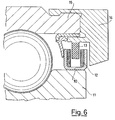
- Fig. 6
- is a different embodiment of the device shown in Fig. 1.
- As shown in Fig. 1, a rolling contact bearing for supporting the wheel of a vehicle has a first ring or
screen 10, integral with the rotatingrace 11 of the bearing. The ring orscreen 10 carries a double magnetizedring 12 with couples of poles opposite in sign, between which a Hall effect magnetic sensor or amagnetoresistive sensor 13 is inserted and carried by a second screen or support 14 integral with thefixed race 15 of the bearing. - The Hall effect
magnetic sensor 13, that has integrated electronic control circuits, is power supplied with the vehicle's voltage. - The signal that is fed to the local processing unit is a function of the n variations of the magnetic field to which the sensor is exposed during a revolution of the bearing. The Hall effect sensor may be of the kind: linear, unipolar, bipolar, bipolar with memory.
- The
magnetic sensor 13, as shown in Fig. 2, is immerged in the magnetic field that is generated by the pole pieces of the n couples of opposite poles alternatively disposed, as shown in the embodiment of Fig. 3. - As shown in Fig. 2, the poles of each ring have the same sign, but it is understood that they can also be realized with alternating signs, NSN on one ring and respectively SNS on the facing ring for all the circumferential extent of the
double ring 12. - The double magnetized
ring 12 can be made of rubber, filled with magnetic elements and fixed or vulcanized to a supporting ring that can also act as the closing memeber of the magnetic flux. Thedouble ring 12 can otherwise be made of plastic and filled with magnetic elements, or made of magnetic sinters or even of elementar magnets. - The material of which the ring is made can have isotropic or anisotropic characteristics.
- The
double ring 12 may have either a magnetic field that is radial with respect to the axis of the bearing, as shown in Fig. 1, or axial as shown in fig. 6, without changing any of the benefits of this invention. - The rotation of the double
magnetized ring 12 causes the Hall effectmagnetic sensor 13 to detect variations of the intensity of the magnetic field in the case of Fig. 2, and variations and inversions of the magnetic field in the case of Fig. 3. - After some necessary processing, the signal that is proportional to the speed is emitted by the electronics that are integrated with the
Hall effect sensor 13, and is sent to the local processing unit. - The sensor unit can also consist of two or more
magnetic sensors 13 with integrated electronics in order to allow detection of the rotation by using a smaller number of magnetic poles, the frequencies obtained by the single ones being equal. - For this application the sensors have to be shifted by a suitable angle or located in correspondence of two opposite couples as shown schematically in Figs. 4 and 5 that correspond to the embodiments of Figs. 2 and 3.
- The same multi-sensing system can also be utilized for detecting the direction of rotation of the wheel by adding a further output.
Claims (2)
- A device for determining the relative rotational speed between the races (11,15) of a rolling contact bearing, comprising a magnetised ring (12) with couples of magnetic poles carried by a first screen (10) of annular shape fixed to the rotating race (11) of the bearing, said magnetised ring (12) facing at least one magnetic sensor (13) carried by a second screen (14) fixed to the stationary race (15) of the bearing;
characterised in that the magnetised ring (12) is a double ring formed by two coaxially spaced apart magnetised rings with couples of poles opposite in sign, the two rings being carried by said first screen (10); the magnetic sensor (13) being inserted between the two spaced apart rings (12) and the first screen (10) so as to be protected towards the outside of the bearing by means of said spaced apart rings (12), said first screen (10) and said second screen (14). - A device according to claim 1 wherein the two axially spaced magnetised rings (12) are fitted on opposite facing walls of said first screen (10).
Applications Claiming Priority (2)
| Application Number | Priority Date | Filing Date | Title |
|---|---|---|---|
| IT6749090 | 1990-07-04 | ||
| IT67490A IT1240482B (en) | 1990-07-04 | 1990-07-04 | DEVICE SUITABLE FOR ALLOWING THE ROTATION SPEED TO BE DETECTED BETWEEN TWO BODIES IN RELATIVE ROTATION SUCH AS THE SUPPORT BODIES OF A WHEEL OF A VEHICLE. |
Publications (2)
| Publication Number | Publication Date |
|---|---|
| EP0464405A1 EP0464405A1 (en) | 1992-01-08 |
| EP0464405B1 true EP0464405B1 (en) | 1994-09-14 |
Family
ID=11302860
Family Applications (1)
| Application Number | Title | Priority Date | Filing Date |
|---|---|---|---|
| EP91109511A Expired - Lifetime EP0464405B1 (en) | 1990-07-04 | 1991-06-10 | Device for determining the relative rotational speed between the races of a rolling contact bearing |
Country Status (4)
| Country | Link |
|---|---|
| US (1) | US5191284A (en) |
| EP (1) | EP0464405B1 (en) |
| DE (1) | DE69103975T2 (en) |
| IT (1) | IT1240482B (en) |
Families Citing this family (36)
| Publication number | Priority date | Publication date | Assignee | Title |
|---|---|---|---|---|
| DE4138867C2 (en) * | 1990-11-28 | 2002-07-18 | Skf Ind Spa | The railcar axle |
| IT223257Z2 (en) * | 1991-05-03 | 1995-06-21 | Skf Ind Spa | ROLLING BEARING WITH ROTATION DETECTION DEVICE, AND ELATIVE ASSEMBLY UNIT. |
| FR2678691B1 (en) * | 1991-07-05 | 1995-04-21 | Skf France | ROTATION SPEED SENSOR DEVICE FOR BEARINGS AND BEARING EQUIPPED WITH SUCH A DEVICE. |
| IT1256785B (en) * | 1992-01-28 | 1995-12-15 | Skf Ind Spa | SEALING COMPLEX WITH A SENSOR DEVICE ON BOARD, FOR A ROLLING BEARING. |
| FR2688060B1 (en) * | 1992-02-28 | 1994-04-15 | Snr Roulements | MAGNET STRUCTURE FOR DISPLACEMENT SENSOR. |
| US5757179A (en) * | 1994-03-04 | 1998-05-26 | Cts Corporation | Position sensor with improved magnetic circuit |
| US5798639A (en) * | 1994-03-04 | 1998-08-25 | Cts Corporation | Rotary position sensor with improved bearing tolerance |
| CA2143811A1 (en) * | 1994-03-04 | 1995-09-05 | Jeffrey L. Mccurley | Field strength position sensor with improved bearing tolerance in reduced space |
| US5596271A (en) * | 1994-05-03 | 1997-01-21 | Multicraft International | Method of and apparatus for detecting the rotation rate of an air moving fan |
| US5955881A (en) * | 1994-10-18 | 1999-09-21 | Cts Corporation | Linkage position sensor having a magnet with two ramped sections for providing variable magnetic field |
| DE19503469C1 (en) * | 1995-02-03 | 1996-05-30 | Freudenberg Carl Fa | Seal for relatively rotating components cooperating with rotation sensor |
| EP0751311B1 (en) * | 1995-03-16 | 2005-02-16 | Nsk Ltd | Rolling bearing unit with rotating speed sensor |
| CA2175946A1 (en) * | 1995-06-06 | 1996-12-07 | Brian G. Babin | Apparatus for sensing the speed of a rotating element |
| US5739684C1 (en) * | 1996-08-19 | 2002-06-18 | Webb Wheel Products Inc | Unitarily formed hub and abs exciter ring |
| US6124710A (en) * | 1998-11-13 | 2000-09-26 | Cts Corporation | Rotary magnetic encoder using hall effect for detecting revolution of a shaft |
| US6288534B1 (en) | 1999-02-10 | 2001-09-11 | Cts Corporation | Non-contacting throttle valve position sensor |
| FR2790800B1 (en) | 1999-03-10 | 2001-04-20 | Roulements Soc Nouvelle | PREASSEMBLY ASSEMBLY FORMING A SEAL WITH INCORPORATED ENCODER AND BEARING OR BEARING COMPRISING SUCH AN ASSEMBLY |
| FR2792380B1 (en) † | 1999-04-14 | 2001-05-25 | Roulements Soc Nouvelle | BEARING PROVIDED WITH A DEVICE FOR DETECTING MAGNETIC PULSES FROM AN ENCODER, SUCH DEVICE COMPRISING SEVERAL ALIGNED SENSITIVE ELEMENTS |
| US6222359B1 (en) | 1999-06-18 | 2001-04-24 | Cts Corporation | Non-contacting position sensor using radial bipolar tapered magnets |
| JP2001304805A (en) * | 2000-04-25 | 2001-10-31 | Tokai Rika Co Ltd | Detecting device for rotational angle |
| US6584838B2 (en) * | 2001-01-11 | 2003-07-01 | Sensor Solutions Corporation | Angular position sensor |
| US6564632B2 (en) | 2001-01-11 | 2003-05-20 | Rochester Gauges, Inc. | Liquid level gauge with removable hall device |
| GB0114279D0 (en) * | 2001-06-12 | 2001-08-01 | Fast Technology Ag | Disc magnetic torque sensing |
| US6909281B2 (en) | 2002-07-03 | 2005-06-21 | Fisher Controls International Llc | Position sensor using a compound magnetic flux source |
| US6911817B2 (en) * | 2002-12-23 | 2005-06-28 | American Electronics Components, Inc. | Wheel-speed sensor |
| BRPI0407499B1 (en) * | 2003-02-21 | 2017-12-19 | Fisher Controls International Llc | POSITION SENSOR ASSEMBLY, AND, METHOD FOR DETECTING RELATIVE POSITION |
| US7293578B2 (en) | 2004-01-22 | 2007-11-13 | Rochester Gauges, Inc. | Gauge assembly having a stop fill device |
| US7726334B2 (en) | 2004-01-22 | 2010-06-01 | Rochester Gauges, Inc. | Service valve assembly having a stop-fill device and remote liquid level indicator |
| US7921873B2 (en) | 2004-01-22 | 2011-04-12 | Rochester Gauges, Inc. | Service valve assembly having a stop-fill device and a liquid level indicating dial |
| US20060261803A1 (en) * | 2005-04-28 | 2006-11-23 | Faetanini Steven E | Cassette seal assembly |
| USD583693S1 (en) | 2006-03-30 | 2008-12-30 | Rochester Gauges, Inc. | Dial assembly for a gauge |
| US20100229964A1 (en) * | 2006-08-18 | 2010-09-16 | Rochester Gauges, Inc. | Service valve assembly having a stop-fill device and remote liquid level indicator |
| US7690323B2 (en) * | 2007-10-31 | 2010-04-06 | Rochester Gauges, Inc. | Gauge head assembly with non-magnetic insert |
| DE102015208837B4 (en) * | 2015-05-13 | 2017-03-30 | Schaeffler Technologies AG & Co. KG | Sensor arrangement with an angle sensor and rolling bearing arrangement with sensor arrangement |
| IT201800010206A1 (en) * | 2018-11-09 | 2020-05-09 | Skf Ab | DETECTION DEVICE FOR WHEELHUB GROUP |
| WO2021195118A1 (en) * | 2020-03-23 | 2021-09-30 | Moog Inc. | Variable reluctance resolver using surface mounted inductors and/or transformers |
Family Cites Families (11)
| Publication number | Priority date | Publication date | Assignee | Title |
|---|---|---|---|---|
| GB893986A (en) * | 1958-10-28 | 1962-04-18 | Ferranti Ltd | Improvements relating to electrical impulsing devices |
| DE1281549B (en) * | 1962-11-15 | 1968-10-31 | Siemens Ag | Electronic pulse generator for an electricity meter with a rotor, which emits a number of pulses corresponding to the rotor rotation angle |
| US3786272A (en) * | 1972-11-03 | 1974-01-15 | Veeder Industries Inc | Hall effect rotary pulse generator |
| GB1504791A (en) * | 1975-02-13 | 1978-03-22 | Polymotor Italiana Spa | Rotational speed transducer |
| US4110676A (en) * | 1976-08-30 | 1978-08-29 | Reliance Electric Company | Dynamoelectric machine and tachometer |
| US4119911A (en) * | 1977-04-22 | 1978-10-10 | Johnson Clark E Jun | Magnetoresistor displacement sensor using a magnetoresistor positioned between relatively moving magnetized toothed members |
| JPS598761B2 (en) * | 1978-02-06 | 1984-02-27 | ソニ−マグネスケ−ル株式会社 | position detection device |
| DE3223308C2 (en) * | 1981-07-17 | 1987-03-05 | Aisin Seiki K.K., Kariya, Aichi | Rotary signal generator |
| US4570118A (en) * | 1981-11-20 | 1986-02-11 | Gulf & Western Manufacturing Company | Angular position transducer including permanent magnets and Hall Effect device |
| FR2599794B1 (en) * | 1986-06-10 | 1991-06-07 | Roulements Soc Nouvelle | BEARING OR BEARING WITH INFORMATION SENSOR |
| US5051693A (en) * | 1990-09-07 | 1991-09-24 | The Torrington Company | Bearing seat encoder mount for rotational parameter sensor apparatus |
-
1990
- 1990-07-04 IT IT67490A patent/IT1240482B/en active IP Right Grant
-
1991
- 1991-06-10 EP EP91109511A patent/EP0464405B1/en not_active Expired - Lifetime
- 1991-06-10 DE DE69103975T patent/DE69103975T2/en not_active Expired - Fee Related
- 1991-07-01 US US07/723,746 patent/US5191284A/en not_active Expired - Fee Related
Also Published As
| Publication number | Publication date |
|---|---|
| DE69103975D1 (en) | 1994-10-20 |
| IT9067490A1 (en) | 1992-01-04 |
| US5191284A (en) | 1993-03-02 |
| IT9067490A0 (en) | 1990-07-04 |
| IT1240482B (en) | 1993-12-17 |
| DE69103975T2 (en) | 1995-02-02 |
| EP0464405A1 (en) | 1992-01-08 |
Similar Documents
| Publication | Publication Date | Title |
|---|---|---|
| EP0464404B1 (en) | Device for determining the relative rotational speed between the races of a rolling contact bearing | |
| EP0464405A1 (en) | Device for determining the relative rotational speed between the races of a rolling contact bearing | |
| US4875785A (en) | Thrust bearing with a magnetic field detector | |
| US5157966A (en) | Transmission speed sensor | |
| US3500091A (en) | Electrical rotational speed sensing device | |
| JP3459784B2 (en) | Device for detecting rotational speed, wheel assembly for inline skate having the device | |
| US5850141A (en) | Annular speed sensor with a tone ring having both axial and radial magnetic fields | |
| US5248939A (en) | Apparatus for sensing the direction and speed of a steering wheel shaft using hall effect sensors in a detachable sensor mounting | |
| US5382098A (en) | Sealing device including an encoding element for a bearing, and bearing equipped with such a device | |
| EP0438624A1 (en) | Device enabling the revolutionary speed to be measured between the races of a rolling bearing for the support of a vehicle wheel | |
| US5130650A (en) | Bearing with a magnetic field angular position sensor | |
| JP2004003918A (en) | Rolling bearing unit for wheel support with load measuring device | |
| GB2251694A (en) | Rotational speed sensing device integrated in a wheel hub bearing | |
| KR970007464B1 (en) | Bearing with magnetic field detector | |
| US3716788A (en) | Tachometer generator | |
| EP0397309A2 (en) | Bearing assemblies | |
| JPH08136558A (en) | Rotation speed detector | |
| EP0464403A1 (en) | Device for determining the relative rotational speed between two members, such as the support members of a vehicle wheel | |
| EP0557931A1 (en) | Device for measuring rotational speed | |
| KR940006597B1 (en) | Transmission speed sensor | |
| GB2050627A (en) | Improvements in mechanical assemblies employing sensing means for sensing motion or position | |
| JP2004084798A (en) | Roller bearing device | |
| KR20230160215A (en) | Absolute position detection device and detection method of rotating body using magnetic material | |
| JP2004076752A (en) | Rolling bearing device | |
| JP4151269B2 (en) | Rolling bearing device with rotation detector |
Legal Events
| Date | Code | Title | Description |
|---|---|---|---|
| PUAI | Public reference made under article 153(3) epc to a published international application that has entered the european phase |
Free format text: ORIGINAL CODE: 0009012 |
|
| AK | Designated contracting states |
Kind code of ref document: A1 Designated state(s): DE FR GB NL |
|
| 17P | Request for examination filed |
Effective date: 19920612 |
|
| 17Q | First examination report despatched |
Effective date: 19930923 |
|
| GRAA | (expected) grant |
Free format text: ORIGINAL CODE: 0009210 |
|
| AK | Designated contracting states |
Kind code of ref document: B1 Designated state(s): DE FR GB NL |
|
| REF | Corresponds to: |
Ref document number: 69103975 Country of ref document: DE Date of ref document: 19941020 |
|
| ET | Fr: translation filed | ||
| PLBE | No opposition filed within time limit |
Free format text: ORIGINAL CODE: 0009261 |
|
| STAA | Information on the status of an ep patent application or granted ep patent |
Free format text: STATUS: NO OPPOSITION FILED WITHIN TIME LIMIT |
|
| 26N | No opposition filed | ||
| PGFP | Annual fee paid to national office [announced via postgrant information from national office to epo] |
Ref country code: FR Payment date: 20010517 Year of fee payment: 11 |
|
| PGFP | Annual fee paid to national office [announced via postgrant information from national office to epo] |
Ref country code: GB Payment date: 20010521 Year of fee payment: 11 |
|
| PGFP | Annual fee paid to national office [announced via postgrant information from national office to epo] |
Ref country code: NL Payment date: 20010522 Year of fee payment: 11 |
|
| PGFP | Annual fee paid to national office [announced via postgrant information from national office to epo] |
Ref country code: DE Payment date: 20010523 Year of fee payment: 11 |
|
| REG | Reference to a national code |
Ref country code: GB Ref legal event code: IF02 |
|
| PG25 | Lapsed in a contracting state [announced via postgrant information from national office to epo] |
Ref country code: GB Free format text: LAPSE BECAUSE OF NON-PAYMENT OF DUE FEES Effective date: 20020610 |
|
| PG25 | Lapsed in a contracting state [announced via postgrant information from national office to epo] |
Ref country code: NL Free format text: LAPSE BECAUSE OF NON-PAYMENT OF DUE FEES Effective date: 20030101 Ref country code: DE Free format text: LAPSE BECAUSE OF NON-PAYMENT OF DUE FEES Effective date: 20030101 |
|
| GBPC | Gb: european patent ceased through non-payment of renewal fee |
Effective date: 20020610 |
|
| PG25 | Lapsed in a contracting state [announced via postgrant information from national office to epo] |
Ref country code: FR Free format text: LAPSE BECAUSE OF NON-PAYMENT OF DUE FEES Effective date: 20030228 |
|
| NLV4 | Nl: lapsed or anulled due to non-payment of the annual fee |
Effective date: 20030101 |
|
| REG | Reference to a national code |
Ref country code: FR Ref legal event code: ST |