EP0463868B1 - Disposable spray dispensing assembly - Google Patents
Disposable spray dispensing assembly Download PDFInfo
- Publication number
- EP0463868B1 EP0463868B1 EP91305773A EP91305773A EP0463868B1 EP 0463868 B1 EP0463868 B1 EP 0463868B1 EP 91305773 A EP91305773 A EP 91305773A EP 91305773 A EP91305773 A EP 91305773A EP 0463868 B1 EP0463868 B1 EP 0463868B1
- Authority
- EP
- European Patent Office
- Prior art keywords
- container
- hole
- assembly
- spray head
- leg
- Prior art date
- Legal status (The legal status is an assumption and is not a legal conclusion. Google has not performed a legal analysis and makes no representation as to the accuracy of the status listed.)
- Expired - Lifetime
Links
Images

Classifications
-
- B—PERFORMING OPERATIONS; TRANSPORTING
- B05—SPRAYING OR ATOMISING IN GENERAL; APPLYING FLUENT MATERIALS TO SURFACES, IN GENERAL
- B05B—SPRAYING APPARATUS; ATOMISING APPARATUS; NOZZLES
- B05B7/00—Spraying apparatus for discharge of liquids or other fluent materials from two or more sources, e.g. of liquid and air, of powder and gas
- B05B7/24—Spraying apparatus for discharge of liquids or other fluent materials from two or more sources, e.g. of liquid and air, of powder and gas with means, e.g. a container, for supplying liquid or other fluent material to a discharge device
- B05B7/2402—Apparatus to be carried on or by a person, e.g. by hand; Apparatus comprising containers fixed to the discharge device
- B05B7/2405—Apparatus to be carried on or by a person, e.g. by hand; Apparatus comprising containers fixed to the discharge device using an atomising fluid as carrying fluid for feeding, e.g. by suction or pressure, a carried liquid from the container to the nozzle
- B05B7/2435—Apparatus to be carried on or by a person, e.g. by hand; Apparatus comprising containers fixed to the discharge device using an atomising fluid as carrying fluid for feeding, e.g. by suction or pressure, a carried liquid from the container to the nozzle the carried liquid and the main stream of atomising fluid being brought together by parallel conduits placed one inside the other
-
- B—PERFORMING OPERATIONS; TRANSPORTING
- B05—SPRAYING OR ATOMISING IN GENERAL; APPLYING FLUENT MATERIALS TO SURFACES, IN GENERAL
- B05B—SPRAYING APPARATUS; ATOMISING APPARATUS; NOZZLES
- B05B9/00—Spraying apparatus for discharge of liquids or other fluent material, without essentially mixing with gas or vapour
- B05B9/03—Spraying apparatus for discharge of liquids or other fluent material, without essentially mixing with gas or vapour characterised by means for supplying liquid or other fluent material
- B05B9/04—Spraying apparatus for discharge of liquids or other fluent material, without essentially mixing with gas or vapour characterised by means for supplying liquid or other fluent material with pressurised or compressible container; with pump
-
- B—PERFORMING OPERATIONS; TRANSPORTING
- B05—SPRAYING OR ATOMISING IN GENERAL; APPLYING FLUENT MATERIALS TO SURFACES, IN GENERAL
- B05B—SPRAYING APPARATUS; ATOMISING APPARATUS; NOZZLES
- B05B7/00—Spraying apparatus for discharge of liquids or other fluent materials from two or more sources, e.g. of liquid and air, of powder and gas
- B05B7/24—Spraying apparatus for discharge of liquids or other fluent materials from two or more sources, e.g. of liquid and air, of powder and gas with means, e.g. a container, for supplying liquid or other fluent material to a discharge device
- B05B7/2402—Apparatus to be carried on or by a person, e.g. by hand; Apparatus comprising containers fixed to the discharge device
- B05B7/2405—Apparatus to be carried on or by a person, e.g. by hand; Apparatus comprising containers fixed to the discharge device using an atomising fluid as carrying fluid for feeding, e.g. by suction or pressure, a carried liquid from the container to the nozzle
- B05B7/2408—Apparatus to be carried on or by a person, e.g. by hand; Apparatus comprising containers fixed to the discharge device using an atomising fluid as carrying fluid for feeding, e.g. by suction or pressure, a carried liquid from the container to the nozzle characterised by the container or its attachment means to the spray apparatus
Definitions
- This invention relates to a disposable spray dispensing assembly adapted for detachable connection to a source of pressurized air for applying adhesives, coatings, sealants, solvents, penetrants, lubricants and the like.
- Air operated liquid spray dispenser assemblies typically include a spray head with a control valve, and a container releasably connected to the spray head.
- the container In preparation for use, the container is usually filled with liquid materials from a larger, bulk container, and the container is then coupled to the spray head which in turn is connected to an air hose.
- the spray head At the end of a spraying operation, the spray head is detached from the hose, and the container is detached from the spray head, and both the spray head and the container are then cleaned in preparation for the next spray operation.
- Such spray dispensers include a disposable, bag-like container that is non-releasably fixed to a spray nozzle assembly which, in turn, is adapted for detachable connection with a reusable air gun handle that includes a control valve.
- a rupturable barrier within the bag container prevents liquid materials from evaporating or leaking through the spray nozzle during transit.
- the nozzle and attached bag container are removed from the handle and disposed, so that no cleaning is necessary.
- U.S. Patent No. 4,804,144 describes a spray dispenser apparatus that includes a disposable eductor assembly having a dip tube which extends into a screw top container. Both the eductor assembly and the container are detachably connected at separate locations to a tube structure which forms part of an air gun handle. Either the eductor assembly, the container, or both may be disconnected from the tube assembly for disposal when desired.
- the container includes an upper threaded tubular projection which is sealed by a disk having a scored center portion which may be punched out for passage of the dip tube.
- the present invention relates to a spray dispensing assembly for liquid materials, and includes a container having a hole, a cover for initially closing the hole, and means for selectively opening the hole.
- the assembly also includes a spray head having an inlet with a connection for detachable joining with a source of pressurized air, and an outlet for discharging a spray of liquid materials.
- a non-releasable coupling selectively secures the spray head to the container and over the hole in captive fashion after the hole is opened, thereby substantially hindering refilling of the container.
- the container and spray head are removed as a single unit from the pressurized air source for simultaneous disposal.
- the label on the container in all likelihood correctly identifies the container's contents and that other materials have not been added to or substituted for the original contents.
- a spray dispensing assembly 10 of the present invention includes a container 12 that advantageously comprises an otherwise conventional, three piece aerosol can 13 widely available in the industry and manufactured of tin coated steel.
- the can 13 includes a cylindrical section 14 with a soldered side seam, a concave bottom 16 coupled in sealed relation to the section 14, and a domed top 18 that is seamed in leak-free relation to the section 14.
- the top 18 has an upper rolled flange 20 which presents an opening 22 (Fig. 2) that communicates with an internal chamber 24 of the can 13.
- the opening 22, however, is covered by a novel captive cap 26 (see also Figs. 5 and 6) that has an upper, peripheral rolled-over flange 28 that complementally rests atop the flange 20 of the top 18.
- a buna-N synthetic rubber gasket 29, having a 70-80 durometer Shore A hardness, is placed within the flange 28 and is held in place by three dimples 31 (one of which is shown in Fig. 6) before assembly of the cap 26 to the can 13.
- the gasket 29 lies between the flanges 20, 28 as shown in Figs. 1 and 2 to provide a seal between the can 13 and the cap 26 once the cap 26 and can 13 are assembled.
- an expandable collet is placed within a recessed, central cup 30 of the cap 26, and the collet is then radially expanded to form a peripheral crimp 32 (Figs. 1 and 2) in the cylindrical sidewall of the cap 26 immediately below the portion of the top 18 underlying the flange 20.
- the integral cap 26 is made of 0.25 mm tin plated steel.
- the crimp 32 extends through the area where the dimples 31 were previously located, causing the dimples 31 to blend into the crimp 32 and effectively disappear.
- the bottom of the cap 26 has a scored, circular line of weakness 34 that surrounds a cover or central cover portion 36 having a small recess 38 located on one side of a central reference axis 39 of the cover portion 36.
- a screwdriver or similar tool is placed in the recess 38 and pressure is exerted toward the bottom 16 of the container 12 until the coined central cover portion 36 separates along a major extent of the line of weakness 34 from remaining portions of the cup 30 to thereby establish a hole 40 as shown, for example, in Fig. 2.
- the line of weakness 34 comprises a means for selectively opening the hole 40 by permitting partial separation of the cover portion 36 from areas of the cap 26 adjacent the hole 40.
- the cover portion 36 is bent to an out-of-the-way orientation when the hole 40 is opened, but remains partially joined to the cap 26 in order to avoid interfering with liquids withdrawn through a dip tube 46.
- a spray head 42 has a depending, tubular body 44 that is connected in interference fit relation to an upper end of the dip tube 46.
- the dip tube 46 is cut from roll stock of polyethylene tubing, and as such has an inherent slight curvature to enable a lower end 48 of the dip tube 46 to extend closely to the lower peripheral region of the chamber 24 as shown in Fig. 1.
- the body 44 is circumscribed with a shoulder 50 (Figs. 2 and 3) to provide a positive stop to limit advancement of the dip tube 46 above the shoulder 50 when the dip tube 46 is assembled to the body 44.
- the spray head 42 has a nozzle portion 52 integrally connected to the top of the body 44, and the nozzle portion 52 narrows to an outlet 54 (Fig. 3) for discharging a spray of liquid materials.
- the spray head 42 also includes a tubular inlet 56 having a cylindrical sidewall with opposed J-shaped channel connections 58, 60 (Figs. 1 and 3) for detachable coupling to a source of pressurized air. More particularly, the channel connections 58, 60 are adapted to receive respective, opposed pins of an air gun handle and thus provide a releasable bayonet or twist-lock coupling between the handle and the spray head 42.
- the gun handle includes a trigger valve for controlling the flow rate of pressurized air directed into the inlet 56, and a representative handle is described in the aforementioned U.S. Patent No. 4,936,511.
- a venturi nozzle insert 62 (Fig. 3) directs pressurized air from the inlet 56 toward the outlet 54 through a central passage, and the flow of air establishes negative pressure conditions in the tubular body 44 and the dip tube 46 to withdraw liquid materials from the chamber 24.
- the insert 62 has an endmost, annular flange 66 that is received in the inlet 56 and functions to retain remaining portions of the insert 62 in coaxial alignment and spaced apart from inner walls of the nozzle portion 52.
- a gasket 67 is adapted to sealingly engage the end of the detachable air gun handle.
- a nonreleasable coupling 68 selectively secures the spray head 42 to the cap 26 of the container 12 and over the hole 40 in captive fashion after the hole 40 is opened.
- the coupling 68 is illustrated in Figs. 1-4, and includes an annular wall 70 that is integral with the body 44. Two opposed notches 72 (Figs. 2 and 4) are formed in an outer portion of the wall 70.
- the coupling 68 includes a generally cylindrical, hollow, skirt-like leg 74 that integrally depends from the wall 70 and surrounds an upper portion of the body 44.
- a lower, outer surface 76 of the leg 74 is tapered and is separated from an annular, outwardly extending stop 78 of the leg 74 by a groove 80 (Fig. 3) that circumscribes the leg 74.
- leg 74 Opposite sides of the leg 74 each have a keyhole-shaped relief aperture 82 (Figs. 1 and 2).
- the spray head 42 and the coupling 68 are integrally molded of polypropylene, and consequently the leg 74 is somewhat resilient.
- the cover portion 36 is opened and the spray head 42 is lowered toward the cup 30 with the dip tube 46 extending through the hole 40, the tapered surface 76 upon engagement with the edge of the cap 26 surrounding the hole 40 will cause opposite side portions of the leg 74 to deflect inwardly until the edge of the cap 26 reaches the groove 80, whereupon the leg 74 will expand in radial fashion due to its inherent resiliency until the edge of the cap 26 surrounding the hole 40 is firmly seated and locked in place in the bottom of the groove 80 as shown in Figs.
- the keyhole shape of the aperture 82 is advantageous in that the enlarged portion of the aperture 82 weakens a central portion of the leg 74 for facilitating inward deflection of the latter, while providing sufficient area for pressure relief as described hereinafter.
- the narrower lower slot-like region of the aperture 82 enables increased engagement of the cap 26 in the groove 80 to facilitate permanent, snap-fit locking attachment of the spray head 42 to the container 12 and yet also provides space for deflection of the leg 74.
- the lower slot-like region of the aperture 82 could be extended if desired to the lower end of the leg 74 to separate the latter into two spaced apart portions, but the leg 74 is somewhat stiffer when constructed as shown which increases the likelihood that the cap 26 will remain firmly seated in the bottom of the groove 80.
- the thickness of the groove 80 is approximately three times the thickness of the cup 30 in order to receive the portion of the cap 26 surrounding the hole 40 as well as the section of the cover portion 36 in the region of the line of weakness 34 that does not completely fracture when the cover portion 36 is opened and moved toward the domed top 18 and against the cup 30.
- the wall 70 extends over the upper flange 28 of the cap 26 to hinder excessive rocking of the spray head 42 that might otherwise permit the cap 26 to disengage the groove 80 and thereby enable release of the leg 74 from the cap 26.
- the wall 70 also provides a shield to hinder insertion of a prying object such as a screwdriver toward the leg 74 during attempts to intentionally deflect the leg 74 inwardly to release the spray head 42 from the cap 26.
- a prying object such as a screwdriver toward the leg 74 during attempts to intentionally deflect the leg 74 inwardly to release the spray head 42 from the cap 26.
- the wall 70 since the wall 70 is spaced closely adjacent the flange 28, the wall 70 cooperates with the stop 78 to prevent undue rocking or tilting of the spray head 42 when a lateral deflection is exerted on the latter in an attempt to separate the spray head 42 from the cap 26.
- the combined free area of the apertures 82 is large enough to prevent substantial increase of pressure in the chamber 24 should the spray head outlet 54 or other regions of the nozzle portion 52 become clogged for any reason.
- excessive pressure within the chamber 24 is relieved by venting the air through the annular space between the leg 74 and the body 44, and thence through the apertures 82 in areas above the groove 80. The air then flows through the small annular space between the wall 70 and the flange 28, or alternatively through the two notches 72.
- the wall 70 serves as a shield to deflect liquid materials escaping the chamber 24 away from the user's face.
- the coupling 68 non-releasably couples the spray head 42 to the container 12 in captive fashion, and thereby prevents refilling of the chamber 24. It is realized, however, that under some circumstances it may be possible to exert such a substantial force on the coupling 68 (as may occur, for example, when the spray head 42 is excessively tilted and/or pulled) that the plastic coupling 68 may deform or fracture in areas adjacent the groove 80 sufficiently to enable the leg 74 to be released from the hole 40.
Landscapes
- Containers And Packaging Bodies Having A Special Means To Remove Contents (AREA)
- Nozzles (AREA)
Description
- This invention relates to a disposable spray dispensing assembly adapted for detachable connection to a source of pressurized air for applying adhesives, coatings, sealants, solvents, penetrants, lubricants and the like.
- Air operated liquid spray dispenser assemblies typically include a spray head with a control valve, and a container releasably connected to the spray head. In preparation for use, the container is usually filled with liquid materials from a larger, bulk container, and the container is then coupled to the spray head which in turn is connected to an air hose. At the end of a spraying operation, the spray head is detached from the hose, and the container is detached from the spray head, and both the spray head and the container are then cleaned in preparation for the next spray operation.
- Conventional spray heads have relatively small passageways, and thus are difficult to clean when used with certain liquid materials. In some instances, solvents may be used but are relatively expensive and somewhat hazardous. Moreover, such sprayers are not practical to use for liquids such as adhesives that cure and cannot be subsequently removed by solvents.
- Recent developments in the art of air operated spray dispensers are described in U.S. Patent Nos. 4,936,511 and 4,971,251, both of which are assigned to the assignee of the present invention. Such spray dispensers include a disposable, bag-like container that is non-releasably fixed to a spray nozzle assembly which, in turn, is adapted for detachable connection with a reusable air gun handle that includes a control valve. A rupturable barrier within the bag container prevents liquid materials from evaporating or leaking through the spray nozzle during transit. At the end of a work operation, the nozzle and attached bag container are removed from the handle and disposed, so that no cleaning is necessary.
- However, shipping regulations in certain jurisdictions prevent or at least hinder shipping liquid materials in bag-like containers if the liquid materials include any solvents or flammable compositions. Moreover, there is a continuing interest in reducing the expenses associated with the spray nozzles and containers and the accompanying costs of filling the containers. As such, it is often prudent to consider the use of conventional liquid containers that are widely available and inexpensive to purchase and fill.
- U.S. Patent No. 4,804,144 describes a spray dispenser apparatus that includes a disposable eductor assembly having a dip tube which extends into a screw top container. Both the eductor assembly and the container are detachably connected at separate locations to a tube structure which forms part of an air gun handle. Either the eductor assembly, the container, or both may be disconnected from the tube assembly for disposal when desired. The container includes an upper threaded tubular projection which is sealed by a disk having a scored center portion which may be punched out for passage of the dip tube.
- However, the spray apparatus described in U.S. Patent No. 4,804,144 is not entirely satisfactory when such a container is to be used as a shipping container and is labeled to identify the contents therein because of the possibility that the container may be refilled with another composition. In such circumstances, the container no longer correctly identifies the contents and may not sufficiently warn the operator of hazards associated with the contents (which is more of a potential problem if the apparatus is used by more than one person). Further, if the container is not sufficiently cleaned between uses, the new liquid contents may be contaminated or react with small amounts of the liquid materials originally packaged in the container.
- The present invention relates to a spray dispensing assembly for liquid materials, and includes a container having a hole, a cover for initially closing the hole, and means for selectively opening the hole. The assembly also includes a spray head having an inlet with a connection for detachable joining with a source of pressurized air, and an outlet for discharging a spray of liquid materials. A non-releasable coupling selectively secures the spray head to the container and over the hole in captive fashion after the hole is opened, thereby substantially hindering refilling of the container.
- At the end of a spraying operation, the container and spray head are removed as a single unit from the pressurized air source for simultaneous disposal. Thus, one can be assured that the label on the container in all likelihood correctly identifies the container's contents and that other materials have not been added to or substituted for the original contents.
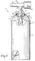
- Fig. 1 is a side elevational view with parts broken away in section of a spray dispensing assembly constructed in accordance with the present invention;
- Fig. 2 is an enlarged, fragmentary, sectional view of the dispensing assembly shown in Fig. 1 taken along lines 2-2 of Fig. 1;
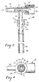
- Fig. 3 is a sectional view of a spray head and non-releasable coupling of the assembly shown in Figs. 1 and 2;
- Fig. 4 is a plan view of the spray head depicted in Fig. 3;
- Fig. 5 is an enlarged plan view of a coined cap before assembly of the cap to a can of the assembly shown in Figs. 1 and 2; and
- Fig. 6 is a side cross-sectional view of the cap shown in Fig. 5.
- Referring initially to Figs. 1 and 2, a
spray dispensing assembly 10 of the present invention includes acontainer 12 that advantageously comprises an otherwise conventional, three piece aerosol can 13 widely available in the industry and manufactured of tin coated steel. Thecan 13 includes acylindrical section 14 with a soldered side seam, aconcave bottom 16 coupled in sealed relation to thesection 14, and adomed top 18 that is seamed in leak-free relation to thesection 14. - The
top 18 has an upper rolled flange 20 which presents an opening 22 (Fig. 2) that communicates with aninternal chamber 24 of thecan 13. The opening 22, however, is covered by a novel captive cap 26 (see also Figs. 5 and 6) that has an upper, peripheral rolled-overflange 28 that complementally rests atop the flange 20 of thetop 18. A buna-Nsynthetic rubber gasket 29, having a 70-80 durometer Shore A hardness, is placed within theflange 28 and is held in place by three dimples 31 (one of which is shown in Fig. 6) before assembly of thecap 26 to thecan 13. Thegasket 29 lies between theflanges 20, 28 as shown in Figs. 1 and 2 to provide a seal between thecan 13 and thecap 26 once thecap 26 and can 13 are assembled. - During assembly of the
container 12, an expandable collet is placed within a recessed,central cup 30 of thecap 26, and the collet is then radially expanded to form a peripheral crimp 32 (Figs. 1 and 2) in the cylindrical sidewall of thecap 26 immediately below the portion of thetop 18 underlying the flange 20. Theintegral cap 26 is made of 0.25 mm tin plated steel. Thecrimp 32 extends through the area where thedimples 31 were previously located, causing thedimples 31 to blend into thecrimp 32 and effectively disappear. - As shown in Figs. 5 and 6, the bottom of the
cap 26 has a scored, circular line ofweakness 34 that surrounds a cover orcentral cover portion 36 having asmall recess 38 located on one side of acentral reference axis 39 of thecover portion 36. When it is desired to open thecontainer 12 for a spray dispensing operation, a screwdriver or similar tool is placed in therecess 38 and pressure is exerted toward thebottom 16 of thecontainer 12 until the coinedcentral cover portion 36 separates along a major extent of the line ofweakness 34 from remaining portions of thecup 30 to thereby establish ahole 40 as shown, for example, in Fig. 2. As such, the line ofweakness 34 comprises a means for selectively opening thehole 40 by permitting partial separation of thecover portion 36 from areas of thecap 26 adjacent thehole 40. Typically, thecover portion 36 is bent to an out-of-the-way orientation when thehole 40 is opened, but remains partially joined to thecap 26 in order to avoid interfering with liquids withdrawn through adip tube 46. - Referring now to Figs. 1-4, a
spray head 42 has a depending,tubular body 44 that is connected in interference fit relation to an upper end of thedip tube 46. Preferably, thedip tube 46 is cut from roll stock of polyethylene tubing, and as such has an inherent slight curvature to enable alower end 48 of thedip tube 46 to extend closely to the lower peripheral region of thechamber 24 as shown in Fig. 1. Thebody 44 is circumscribed with a shoulder 50 (Figs. 2 and 3) to provide a positive stop to limit advancement of thedip tube 46 above theshoulder 50 when thedip tube 46 is assembled to thebody 44. - The
spray head 42 has anozzle portion 52 integrally connected to the top of thebody 44, and thenozzle portion 52 narrows to an outlet 54 (Fig. 3) for discharging a spray of liquid materials. Thespray head 42 also includes atubular inlet 56 having a cylindrical sidewall with opposed J-shaped channel connections 58, 60 (Figs. 1 and 3) for detachable coupling to a source of pressurized air. More particularly, thechannel connections spray head 42. The gun handle includes a trigger valve for controlling the flow rate of pressurized air directed into theinlet 56, and a representative handle is described in the aforementioned U.S. Patent No. 4,936,511. - A venturi nozzle insert 62 (Fig. 3) directs pressurized air from the
inlet 56 toward theoutlet 54 through a central passage, and the flow of air establishes negative pressure conditions in thetubular body 44 and thedip tube 46 to withdraw liquid materials from thechamber 24. Theinsert 62 has an endmost,annular flange 66 that is received in theinlet 56 and functions to retain remaining portions of theinsert 62 in coaxial alignment and spaced apart from inner walls of thenozzle portion 52. Agasket 67 is adapted to sealingly engage the end of the detachable air gun handle. - A
nonreleasable coupling 68 selectively secures thespray head 42 to thecap 26 of thecontainer 12 and over thehole 40 in captive fashion after thehole 40 is opened. Thecoupling 68 is illustrated in Figs. 1-4, and includes anannular wall 70 that is integral with thebody 44. Two opposed notches 72 (Figs. 2 and 4) are formed in an outer portion of thewall 70. - The
coupling 68 includes a generally cylindrical, hollow, skirt-like leg 74 that integrally depends from thewall 70 and surrounds an upper portion of thebody 44. A lower,outer surface 76 of theleg 74 is tapered and is separated from an annular, outwardly extendingstop 78 of theleg 74 by a groove 80 (Fig. 3) that circumscribes theleg 74. - Opposite sides of the
leg 74 each have a keyhole-shaped relief aperture 82 (Figs. 1 and 2). Thespray head 42 and thecoupling 68 are integrally molded of polypropylene, and consequently theleg 74 is somewhat resilient. When thecover portion 36 is opened and thespray head 42 is lowered toward thecup 30 with thedip tube 46 extending through thehole 40, thetapered surface 76 upon engagement with the edge of thecap 26 surrounding thehole 40 will cause opposite side portions of theleg 74 to deflect inwardly until the edge of thecap 26 reaches thegroove 80, whereupon theleg 74 will expand in radial fashion due to its inherent resiliency until the edge of thecap 26 surrounding thehole 40 is firmly seated and locked in place in the bottom of thegroove 80 as shown in Figs. 1 and 2. During insertion of thedip tube 46 andleg 74 into thechamber 24, thesurface 76 engages thecover portion 36 and moves the latter to the orientation shown in Fig. 1 againstcup 30. Thestop 78 substantially prevents further advancement of theleg 74 toward thechamber 24. - The keyhole shape of the
aperture 82 is advantageous in that the enlarged portion of theaperture 82 weakens a central portion of theleg 74 for facilitating inward deflection of the latter, while providing sufficient area for pressure relief as described hereinafter. The narrower lower slot-like region of theaperture 82 enables increased engagement of thecap 26 in thegroove 80 to facilitate permanent, snap-fit locking attachment of thespray head 42 to thecontainer 12 and yet also provides space for deflection of theleg 74. The lower slot-like region of theaperture 82 could be extended if desired to the lower end of theleg 74 to separate the latter into two spaced apart portions, but theleg 74 is somewhat stiffer when constructed as shown which increases the likelihood that thecap 26 will remain firmly seated in the bottom of thegroove 80. The thickness of thegroove 80 is approximately three times the thickness of thecup 30 in order to receive the portion of thecap 26 surrounding thehole 40 as well as the section of thecover portion 36 in the region of the line ofweakness 34 that does not completely fracture when thecover portion 36 is opened and moved toward the domed top 18 and against thecup 30. - The
wall 70 extends over theupper flange 28 of thecap 26 to hinder excessive rocking of thespray head 42 that might otherwise permit thecap 26 to disengage thegroove 80 and thereby enable release of theleg 74 from thecap 26. Thewall 70 also provides a shield to hinder insertion of a prying object such as a screwdriver toward theleg 74 during attempts to intentionally deflect theleg 74 inwardly to release thespray head 42 from thecap 26. Moreover, since thewall 70 is spaced closely adjacent theflange 28, thewall 70 cooperates with thestop 78 to prevent undue rocking or tilting of thespray head 42 when a lateral deflection is exerted on the latter in an attempt to separate thespray head 42 from thecap 26. - The combined free area of the
apertures 82 is large enough to prevent substantial increase of pressure in thechamber 24 should thespray head outlet 54 or other regions of thenozzle portion 52 become clogged for any reason. Viewing Fig. 2, excessive pressure within thechamber 24 is relieved by venting the air through the annular space between theleg 74 and thebody 44, and thence through theapertures 82 in areas above thegroove 80. The air then flows through the small annular space between thewall 70 and theflange 28, or alternatively through the twonotches 72. In such instances, thewall 70 serves as a shield to deflect liquid materials escaping thechamber 24 away from the user's face. - In ordinary use, the
coupling 68 non-releasably couples thespray head 42 to thecontainer 12 in captive fashion, and thereby prevents refilling of thechamber 24. It is realized, however, that under some circumstances it may be possible to exert such a substantial force on the coupling 68 (as may occur, for example, when thespray head 42 is excessively tilted and/or pulled) that theplastic coupling 68 may deform or fracture in areas adjacent thegroove 80 sufficiently to enable theleg 74 to be released from thehole 40. In most circumstances, however, such intentional action would destroy thecoupling 68 adjacent thegroove 80 to such an extent that firm re-coupling of thegroove 80 and thecap 26 would no longer be possible, and thespray head 42 in all likelihood would no longer remain attached in satisfactory fashion to thecontainer 12 when thechamber 24 is pressurized for spraying.
Claims (8)
- A spray dispensing assembly (10) for liquid materials comprising:
a container (12) having a hole (40), a cover (26) for initially closing said hole, and means (34) for selectively opening said hole;
a spray head (42) having an inlet (56) with a connection (58,60) for detachable joining with a source of pressurized air, and an outlet (54) for discharging a spray of liquid materials; characterised by
a non-releasable coupling (68) for selectively securing said spray head to said container and over said hole in captive fashion after said hole is opened, thereby substantially hindering refilling of said container. - The assembly of claim 1, wherein said coupling includes a leg (74) for extension into said hole, and wherein said leg includes a groove (80) for snap-fit reception of said container adjacent said hole.
- The assembly of claim 1; and including a pressure relief aperture (82).
- The assembly of claim 1, wherein said coupling includes a wall (70) extending over said container for hindering excessive tilting of said spray head when said spray head is secured to said container.
- The assembly of claim 4, wherein said coupling includes a leg (74) extending into said container when said spray head is secured to said container, and wherein said wall is positioned to hinder access to said leg.
- The assembly of claim 4, wherein said wall includes a pressure relief notch (72).
- The assembly of claim 1, wherein said container has an opening (40) and includes a captive cap (26) non-releasably covering said opening, and wherein said cap includes said cover.
- The assembly of claim 7, wherein said means for selectively opening said hole comprises a scored line of weakness (34) in said cap.
Applications Claiming Priority (2)
| Application Number | Priority Date | Filing Date | Title |
|---|---|---|---|
| US546109 | 1990-06-29 | ||
| US07/546,109 US5110011A (en) | 1990-06-29 | 1990-06-29 | Non-releasable spray head and dip tube assembly |
Publications (3)
| Publication Number | Publication Date |
|---|---|
| EP0463868A2 EP0463868A2 (en) | 1992-01-02 |
| EP0463868A3 EP0463868A3 (en) | 1992-03-25 |
| EP0463868B1 true EP0463868B1 (en) | 1994-11-23 |
Family
ID=24178907
Family Applications (1)
| Application Number | Title | Priority Date | Filing Date |
|---|---|---|---|
| EP91305773A Expired - Lifetime EP0463868B1 (en) | 1990-06-29 | 1991-06-26 | Disposable spray dispensing assembly |
Country Status (9)
| Country | Link |
|---|---|
| US (2) | US5110011A (en) |
| EP (1) | EP0463868B1 (en) |
| JP (1) | JP2520908Y2 (en) |
| KR (1) | KR960008949Y1 (en) |
| AU (1) | AU640788B2 (en) |
| BR (1) | BR9102671A (en) |
| CA (1) | CA2043929A1 (en) |
| DE (1) | DE69105240T2 (en) |
| ES (1) | ES2064044T3 (en) |
Families Citing this family (23)
| Publication number | Priority date | Publication date | Assignee | Title |
|---|---|---|---|---|
| US5110011A (en) * | 1990-06-29 | 1992-05-05 | Minnesota Mining And Manufacturing Company | Non-releasable spray head and dip tube assembly |
| US5558247A (en) * | 1994-08-19 | 1996-09-24 | Caso; Frank J. | Extension tube clip holder |
| US6129146A (en) * | 1999-05-17 | 2000-10-10 | Krueger; David L. | Manifold for a brazed radiator |
| US7484676B2 (en) * | 2002-10-24 | 2009-02-03 | 3M Innovative Properties Company | Easy clean spray gun |
| US20040195375A1 (en) * | 2003-01-15 | 2004-10-07 | Richard Koeth | Systems and methods for application of tire treatment agent |
| US7207497B2 (en) * | 2003-02-22 | 2007-04-24 | Clark Rikk A | Dry flake sprayer and method |
| US20040206771A1 (en) * | 2003-04-18 | 2004-10-21 | Eric Junkel | Water toy with two port elastic fluid bladder |
| DE102004027789B4 (en) * | 2003-06-11 | 2011-12-08 | Martin Ruda | Replaceable paint spray facility and spray gun |
| US7575134B2 (en) * | 2005-03-17 | 2009-08-18 | Martin James H | Self-sealing nozzle for dispensing apparatus |
| US7731104B2 (en) * | 2006-04-26 | 2010-06-08 | Wagner Spray Tech Corporation | Texture sprayer |
| USD636668S1 (en) | 2008-03-24 | 2011-04-26 | Mary Kay Inc. | Dip tubes |
| US8376192B2 (en) | 2008-03-24 | 2013-02-19 | Mary Kay Inc. | Apparatus for dispensing fluids using a press-fit diptube |
| US9789502B2 (en) | 2008-06-05 | 2017-10-17 | Mary Kay Inc. | Apparatus for dispensing fluids using a removable bottle |
| CN105107653B (en) | 2009-01-26 | 2018-01-09 | 3M创新有限公司 | Liquid spray gun, spray gun platform and nozzle component |
| GB0913488D0 (en) * | 2009-08-01 | 2009-09-16 | Reckitt Benckiser Nv | Product |
| GB201101006D0 (en) | 2011-01-21 | 2011-03-09 | Reckitt Benckiser Nv | Product |
| WO2012109298A1 (en) | 2011-02-09 | 2012-08-16 | 3M Innovative Properties Company | Nozzle tips and spray head assemblies for liquid spray guns |
| EP2736651B2 (en) | 2011-07-28 | 2024-01-10 | 3M Innovative Properties Company | Spray head assembly with integrated air cap/nozzle for a liquid spray gun |
| WO2013055730A1 (en) | 2011-10-12 | 2013-04-18 | 3M Innovative Properties Company | Spray head assemblies for liquid spray guns |
| MX370998B (en) | 2012-03-06 | 2020-01-13 | 3M Innovative Properties Co | Spray gun having internal boost passageway. |
| RU2587438C2 (en) | 2012-03-23 | 2016-06-20 | 3М Инновейтив Пропертиз Компани | Spray gun barrel with fixed tip |
| RU2638399C2 (en) | 2013-07-15 | 2017-12-13 | 3М Инновейтив Пропертиз Компани | Pneumatic caps with shaped inserts for liquid spray guns |
| CN110650809B (en) * | 2017-03-17 | 2022-01-28 | 斯勒冈分配系统公司 | Spraying device and manufacturing method thereof |
Family Cites Families (15)
| Publication number | Priority date | Publication date | Assignee | Title |
|---|---|---|---|---|
| BE624657A (en) * | ||||
| US2090977A (en) * | 1935-05-11 | 1937-08-24 | Glenn R Hoffman | Dispensing apparatus |
| US2101471A (en) * | 1936-05-02 | 1937-12-07 | Greenbaum Martin | Nonrefillable bottle tapping device |
| US5110011A (en) * | 1990-06-29 | 1992-05-05 | Minnesota Mining And Manufacturing Company | Non-releasable spray head and dip tube assembly |
| US3222093A (en) * | 1963-04-11 | 1965-12-07 | Carrier Corp | Fastening apparatus |
| US3524566A (en) * | 1968-08-12 | 1970-08-18 | American Can Co | Straw slot for container closure |
| US3730392A (en) * | 1970-08-03 | 1973-05-01 | Ciba Geigy Corp | Coupler-aspirator-valve assembly |
| IT1071471B (en) * | 1976-10-18 | 1985-04-10 | Spray Plast S R L | MANUAL SPRAYER FOR LIQUIDS |
| US4804144A (en) * | 1981-09-21 | 1989-02-14 | Tekex Company | Apparatus for dispensing viscous materials |
| US4377244A (en) * | 1981-11-16 | 1983-03-22 | Lakeshore Commercial Finance Corporation | Container end and closure therefor |
| US4723684A (en) * | 1983-06-02 | 1988-02-09 | Lambert G Steven | Can lid with integral push-in tab |
| US4653676A (en) * | 1984-12-28 | 1987-03-31 | Gene Stull | Captive cap construction for hand-held dispenser |
| US4767058A (en) * | 1986-06-30 | 1988-08-30 | Chesebrough-Pond's Inc. | Spray head comprising cap member with rotatable/depressible valve held by frangible locking collar |
| FR2617941B1 (en) * | 1987-07-07 | 1989-10-27 | Applic Gaz Sa | VALVE AND VALVE CONTAINER |
| US4976368B1 (en) * | 1989-10-23 | 1996-09-10 | Gerald B Klein | Concentric convenience opening beverage can end |
-
1990
- 1990-06-29 US US07/546,109 patent/US5110011A/en not_active Expired - Lifetime
-
1991
- 1991-05-30 AU AU78076/91A patent/AU640788B2/en not_active Ceased
- 1991-06-05 CA CA002043929A patent/CA2043929A1/en not_active Abandoned
- 1991-06-25 BR BR919102671A patent/BR9102671A/en not_active IP Right Cessation
- 1991-06-26 ES ES91305773T patent/ES2064044T3/en not_active Expired - Lifetime
- 1991-06-26 DE DE69105240T patent/DE69105240T2/en not_active Expired - Fee Related
- 1991-06-26 EP EP91305773A patent/EP0463868B1/en not_active Expired - Lifetime
- 1991-06-27 KR KR2019910009670U patent/KR960008949Y1/en not_active IP Right Cessation
- 1991-06-28 JP JP1991049904U patent/JP2520908Y2/en not_active Expired - Lifetime
-
1992
- 1992-04-14 US US07/859,081 patent/US5236106A/en not_active Expired - Fee Related
Also Published As
| Publication number | Publication date |
|---|---|
| KR920000410U (en) | 1992-01-27 |
| US5110011A (en) | 1992-05-05 |
| CA2043929A1 (en) | 1991-12-30 |
| US5236106A (en) | 1993-08-17 |
| DE69105240T2 (en) | 1995-05-18 |
| JPH0489779U (en) | 1992-08-05 |
| ES2064044T3 (en) | 1995-01-16 |
| DE69105240D1 (en) | 1995-01-05 |
| KR960008949Y1 (en) | 1996-10-11 |
| BR9102671A (en) | 1992-02-04 |
| AU640788B2 (en) | 1993-09-02 |
| JP2520908Y2 (en) | 1996-12-18 |
| EP0463868A2 (en) | 1992-01-02 |
| AU7807691A (en) | 1992-01-02 |
| EP0463868A3 (en) | 1992-03-25 |
Similar Documents
| Publication | Publication Date | Title |
|---|---|---|
| EP0463868B1 (en) | Disposable spray dispensing assembly | |
| US5553748A (en) | Refillable liquid dispenser | |
| JP4896357B2 (en) | Aerosol spray dispenser | |
| CA1291969C (en) | Hygienic liquid dispensing system | |
| EP0109704B1 (en) | Liquid product pouring and measuring package with self draining feature | |
| CA2469945C (en) | Aerosol powder valve | |
| US7886899B2 (en) | Container closure having means for introducing an additive into the contents of the container | |
| US4805814A (en) | Container for liquids having a mounting boss for storage of a removable dispenser | |
| CA2334593C (en) | Aerosol powder valve | |
| EP0517388B1 (en) | Single use spray dispensing assembly | |
| JPH08506553A (en) | Refillable aerosol can with air as high pressure gas | |
| US4702267A (en) | Pesticide rinser | |
| US5465875A (en) | Closed transfer devices for agricultural chemicals and the like | |
| GB2086488A (en) | Apparatus for dispensing liquids under pressure from containers | |
| EP0242606A2 (en) | Spray cap assembly | |
| US5497813A (en) | Apparatus for opening sealed containers | |
| EP0025682B1 (en) | Improvements in casks and like containers | |
| EP0558546B1 (en) | Container supply caps | |
| GB2101225A (en) | Containers for pressurized liquids | |
| GB2109869A (en) | Dispensing container | |
| MXPA98004666A (en) | Packaging container and liqui distributor |
Legal Events
| Date | Code | Title | Description |
|---|---|---|---|
| PUAI | Public reference made under article 153(3) epc to a published international application that has entered the european phase |
Free format text: ORIGINAL CODE: 0009012 |
|
| AK | Designated contracting states |
Kind code of ref document: A2 Designated state(s): DE ES FR GB IT NL |
|
| PUAL | Search report despatched |
Free format text: ORIGINAL CODE: 0009013 |
|
| AK | Designated contracting states |
Kind code of ref document: A3 Designated state(s): DE ES FR GB IT NL |
|
| 17P | Request for examination filed |
Effective date: 19920729 |
|
| 17Q | First examination report despatched |
Effective date: 19940120 |
|
| GRAA | (expected) grant |
Free format text: ORIGINAL CODE: 0009210 |
|
| ITF | It: translation for a ep patent filed |
Owner name: BARZANO' E ZANARDO ROMA S.P.A. |
|
| AK | Designated contracting states |
Kind code of ref document: B1 Designated state(s): DE ES FR GB IT NL |
|
| REF | Corresponds to: |
Ref document number: 69105240 Country of ref document: DE Date of ref document: 19950105 |
|
| REG | Reference to a national code |
Ref country code: ES Ref legal event code: FG2A Ref document number: 2064044 Country of ref document: ES Kind code of ref document: T3 |
|
| ET | Fr: translation filed | ||
| PLBE | No opposition filed within time limit |
Free format text: ORIGINAL CODE: 0009261 |
|
| STAA | Information on the status of an ep patent application or granted ep patent |
Free format text: STATUS: NO OPPOSITION FILED WITHIN TIME LIMIT |
|
| 26N | No opposition filed | ||
| PGFP | Annual fee paid to national office [announced via postgrant information from national office to epo] |
Ref country code: FR Payment date: 19980520 Year of fee payment: 8 |
|
| PGFP | Annual fee paid to national office [announced via postgrant information from national office to epo] |
Ref country code: GB Payment date: 19980526 Year of fee payment: 8 |
|
| PGFP | Annual fee paid to national office [announced via postgrant information from national office to epo] |
Ref country code: NL Payment date: 19980527 Year of fee payment: 8 Ref country code: DE Payment date: 19980527 Year of fee payment: 8 |
|
| PGFP | Annual fee paid to national office [announced via postgrant information from national office to epo] |
Ref country code: ES Payment date: 19980617 Year of fee payment: 8 |
|
| PG25 | Lapsed in a contracting state [announced via postgrant information from national office to epo] |
Ref country code: GB Free format text: LAPSE BECAUSE OF NON-PAYMENT OF DUE FEES Effective date: 19990626 |
|
| PG25 | Lapsed in a contracting state [announced via postgrant information from national office to epo] |
Ref country code: ES Free format text: LAPSE BECAUSE OF EXPIRATION OF PROTECTION Effective date: 19990628 |
|
| PG25 | Lapsed in a contracting state [announced via postgrant information from national office to epo] |
Ref country code: FR Free format text: THE PATENT HAS BEEN ANNULLED BY A DECISION OF A NATIONAL AUTHORITY Effective date: 19990630 |
|
| PG25 | Lapsed in a contracting state [announced via postgrant information from national office to epo] |
Ref country code: NL Free format text: LAPSE BECAUSE OF NON-PAYMENT OF DUE FEES Effective date: 20000101 |
|
| GBPC | Gb: european patent ceased through non-payment of renewal fee |
Effective date: 19990626 |
|
| NLV4 | Nl: lapsed or anulled due to non-payment of the annual fee |
Effective date: 20000101 |
|
| PG25 | Lapsed in a contracting state [announced via postgrant information from national office to epo] |
Ref country code: DE Free format text: LAPSE BECAUSE OF NON-PAYMENT OF DUE FEES Effective date: 20000503 |
|
| REG | Reference to a national code |
Ref country code: FR Ref legal event code: ST |
|
| REG | Reference to a national code |
Ref country code: ES Ref legal event code: FD2A Effective date: 20010601 |
|
| PG25 | Lapsed in a contracting state [announced via postgrant information from national office to epo] |
Ref country code: IT Free format text: LAPSE BECAUSE OF NON-PAYMENT OF DUE FEES;WARNING: LAPSES OF ITALIAN PATENTS WITH EFFECTIVE DATE BEFORE 2007 MAY HAVE OCCURRED AT ANY TIME BEFORE 2007. THE CORRECT EFFECTIVE DATE MAY BE DIFFERENT FROM THE ONE RECORDED. Effective date: 20050626 |