EP0463383B1 - Breathing protection mask with easily changeable breathing filter - Google Patents
Breathing protection mask with easily changeable breathing filter Download PDFInfo
- Publication number
- EP0463383B1 EP0463383B1 EP91108531A EP91108531A EP0463383B1 EP 0463383 B1 EP0463383 B1 EP 0463383B1 EP 91108531 A EP91108531 A EP 91108531A EP 91108531 A EP91108531 A EP 91108531A EP 0463383 B1 EP0463383 B1 EP 0463383B1
- Authority
- EP
- European Patent Office
- Prior art keywords
- breathing
- filter
- sleeve
- mask
- breathing filter
- Prior art date
- Legal status (The legal status is an assumption and is not a legal conclusion. Google has not performed a legal analysis and makes no representation as to the accuracy of the status listed.)
- Expired - Lifetime
Links
Images

Classifications
-
- A—HUMAN NECESSITIES
- A62—LIFE-SAVING; FIRE-FIGHTING
- A62B—DEVICES, APPARATUS OR METHODS FOR LIFE-SAVING
- A62B18/00—Breathing masks or helmets, e.g. affording protection against chemical agents or for use at high altitudes or incorporating a pump or compressor for reducing the inhalation effort
- A62B18/02—Masks
- A62B18/025—Halfmasks
Definitions
- the invention relates to a breathing mask with a breathing filter on a breath connection and a bellows sealing the interior of the mask from the environment, which surrounds the breathing filter at its end facing the interior of the mask in the manner of a rigid sleeve.
- an escape filter device with a breathing filter at the breathing connection has become known, in which the breathing filter is connected to a mask body via a bellows.
- the bellows seals the interior of the mask from the surroundings and encompasses the breathing filter at the filter outlet in the manner of a rigid sleeve. Since the cuff has to perform the holding and sealing function at the same time, it is designed as a clamp placed around the bellows.
- the breathing filter is displaceably arranged in the mask body via the bellows.
- a guide ring is attached to the passage opening of the respiratory filter on the mask body, the guide ring being dimensioned in such a way that the respiratory filter can be easily pushed through.
- the bellows follows the axial displacement of the breathing filter. The stroke is limited by the abutment of the rigid sleeve on the guide ring.
- a breathing mask which is made of resilient plastic and has a bellows-shaped attachment in the area of the breathing connection, into which a breathing filter is inserted.
- the respiratory filter is fixed at the filter inlet by an encircling collar and at the filter outlet by a stop.
- a disadvantage of the known arrangement is that the breathing filter can be removed from the bellows-shaped attachment only with difficulty, since no dimensionally stable, cylindrical receptacle is provided at the filter outlet, and the bellows-shaped attachment has to be turned over the entire length of the filter when the breathing filter is removed. In addition, there is no possibility of fixing an inverted section of the bellows-shaped attachment.
- the invention is therefore based on the object of simplifying the replacement of the breathing filter.
- the object is achieved in that the rigid cuff is continued to an elastic sleeve almost completely encompassing the respiratory filter, the respiratory filter being insertable or removable from the cuff when the sleeve is retracted and fixed in the retracted position.
- the advantage of the invention consists essentially in the fact that a rigid, dimensionally stable sleeve is provided for holding the breathing filter and the fixation and sealing function is taken over by the sleeve adjoining the sleeve.
- the cuff can therefore fit the breathing filter in a clearance fit.
- the cylindrical part of the cuff encompasses the outer surface of the breathing filter and extends to about half the height of the breathing filter and is then continued in an elastic sleeve.
- the sleeve can be made of natural rubber, neoprene or silicone, for example.
- the sleeve fits firmly around the cuff and is fixed in this position.
- the breathing filter can now be removed.
- the sleeve is folded back and fits gas-tight around the outer surface of the respiratory filter.
- the breathing mask is now ready for use again. If the cuff is designed as a clearance fit with respect to the breathing filter, rubber-elastic knobs can be present within the cuff, distributed over the circumference, which fix the breathing filter in the cuff. The knobs prevent the breathing filter from falling out during disassembly.
- the sleeve consists of individual ones strip-shaped sections that run parallel to the breathing filter and are combined in a ring at the filter inlet of the breathing filter. Reinforcements can be inserted into individual sections for stiffening.
- the sleeve can, starting from the sleeve, first be cylindrical, then run in strip-shaped sections and be cylindrical again at the filter inlet. The cylindrical section following the cuff serves as a seal for the breathing filter.
- the strip-shaped sections have the effect that the folding back of the sleeve is facilitated.
- the sleeve is designed as a rubber-elastic strip which surrounds the filter inlet of the breathing filter in a U-shape and the legs of which are attached to the cuff.
- the breathing filter is pressed into the rigid cuff and fixed by the U-shaped strip.
- the strip is wiped off at the side and the breathing filter can be removed.
- the sleeve with a collar at the level of the filter inlet, which surrounds the respiratory filter and presses the respiratory filter against the cuff, so as to enable a firm hold. If the sleeve consists of individual strip-shaped sections, the sections can be fixed individually with the collar on the breathing filter. The length of the sections is such that they are first stretched during assembly and then attached to the breathing filter under the inherent elastic tension.
- the collar As an assembly aid, it is advantageous to equip the collar with individual grip tabs on the front of the filter inlet. By pulling on the The sleeve can be folded back particularly easily using grip tabs.
- the grip tabs can be provided with perforations or washboard-like stiffeners in order to offer a good contact surface and to prevent slipping.
- Inexpensive manufacture of the bellows and sleeve is achieved if they are made in one piece by the sleeve being a continuation of the bellows and the rigid sleeve being created by inserting a rigid band into the cylindrical extension of the bellows.
- This tape can be vulcanized into the outer surface or rest on the inside.
- a rigid band lying against the inside of the cuff is particularly easy to install and has particularly good sliding properties for the egg-clogging breathing filter.
- the breathing filter together with the sleeve can be inserted into the mask body along a guide ring in the mask connection, the length of the drawer being determined by the bellows length.
- the cuff prefferably provides a stop at the filter outlet, against which the breathing filter can be pushed during insertion. It is particularly cost-effective to make the bellows, sleeve and stop in one piece.
- the stop can be designed as a circumferential, bead-shaped lip.
- the sliding band is made of Teflon and is pushed over the sleeve before the breathing filter is inserted.
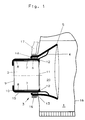
- Fig. 1 shows a breathing mask (1) with a breathing filter (2) on the breathing connection (3) which is attached to a bellows (4).
- the bellows (4) is part of the mask body (5) and seals the mask interior (20) from the surroundings.
- a rigid band (6) is inserted between the bellows (4) and the breathing filter (2), which together with the bellows (4) is a rigid sleeve (7) for holding the breathing filter (2).
- the length of the cuff (7) extends over the length of the band (6).
- the cuff (7) is continued in an elastic sleeve (8) which is gas-tight Breathing filter (2) comprises.
- the breathing filter (2) abuts a collar (10) at the filter inlet (9) and a stop (12) at the filter outlet (11).
- Stop (12), sleeve (7), sleeve (8) and collar (10) are made in one piece with the bellows (4).
- a guide ring (13) is provided in the breathing connection (3) between the sleeve (8) or sleeve (7) and the mask body (5), through which the breathing filter (2) together with the sleeve (8) can be inserted into the mask interior (20) is.
- the length of the drawer is determined by the bellows length.
- the sealing lip (14) presses on all sides on the outside of the cuff (7) and fixes the breathing filter (2) in the position of use. Pushing out the breathing filter (2) into the position of use is made easier when a sliding band (15) is pushed onto the sleeve (8) and the sleeve (7). Particularly good sliding properties are provided if the sliding sleeve (15) is made from Teflon.
- a protective hood (16) and a strap (17) are fastened to the breathing connection (3) with a clamp (16) which is braced against the guide ring (13). The protective hood can be pulled over the head of a device carrier, not shown.
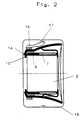
- Fig. 2 shows the breathing mask (1) in a transport container (18) with the breathing filter (2) inserted into the mask interior (20).
- the sealing lip (14) lies over the collar (10) and thus braces the breathing filter (2) in the interior of the mask (20).
- the maximum insertion length is limited by the length of the bellows (4).
- Fig. 3 shows a front view of the breathing filter (2) with folded sleeve (8), a collar (10) surrounding the filter inlet (9) and grip tabs (19), which are arranged at an angle of 90 degrees and a continuation of the collar (10 ) are.
- the sleeve (8) is first pushed back up to the cuff (7) and placed on the outside of the cuff (7).
- the sleeve (8) is gripped by the grip tab (19) and placed over the sleeve (7).
- the breathing filter (2) can now be removed.
- the new breathing filter is inserted into the cuff (7) and bumps against the stop (12). Then the sleeve (8) is folded back.
Description
Die Erfindung betrifft eine Atemschutzmaske mit einem Atemfilter an einem Atemanschluß und einem den Maskeninnenraum gegenüber der Umgebung abdichtenden Balg, welcher das Atemfilter an seinem dem Maskeninnenraum zugewandten Ende in Art einer starren Manschette umgreift.The invention relates to a breathing mask with a breathing filter on a breath connection and a bellows sealing the interior of the mask from the environment, which surrounds the breathing filter at its end facing the interior of the mask in the manner of a rigid sleeve.
Aus der DE-PS 32 36 028, welche die Merkmale des Oberbegriffs von Anspruch 1 zeigt, ist ein Fluchtfiltergerät mit einem Atemfilter am Atemanschluß bekanntgeworden, bei dem das Atemfilter über einen Balg mit einem Maskenkörper verbunden ist. Der Balg dichtet den Maskeninnenraum gegenüber der Umgebung ab und umgreift das Atemfilter am Filterauslaß in Art einer starren Manschette. Da die Manschette gleichzeitig Halte- und Dichtfunktion übernehmen muß, ist sie als eine um den Balg gelegte Schelle ausgeführt. Über den Balg ist das Atemfilter im Maskenkörper verschiebbar angeordnet. An der Durchtrittsöffnung des Atemfilters am Maskenkörper ist ein Führungsring befestigt, der vom Durchmesser so bemessen ist, daß ein leichtes Hindurchschieben des Atemfilters ermöglicht wird. Der Balg folgt hierbei der axialen Verschiebung des Atemfilters. Die Begrenzung des Hubes erfolgt mit dem Anstoß der starren Manschette am führungsring.From DE-PS 32 36 028, which shows the features of the preamble of
Bei dem bekannten Fluchtfiltergerät ist es von Nachteil, daß zum Wechsel des Atemfilters die Manschette zerlegt werden muß, indem die Schelle vom Balg entfernt wird. Dieses ist zeitaufwendig, da die Demontage in dem schwer zugänglichen Maskeninnenraum vorgenommen werden muß und zudem zum Lösen der Schelle Werkzeug notwendig ist.In the known escape filter device, it is disadvantageous that the cuff has to be dismantled in order to change the breathing filter by removing the clamp from the bellows. This is time-consuming since the disassembly has to be carried out in the mask interior, which is difficult to access, and tools are also required to loosen the clamp.
Aus dem DE-GM 67 52 895 ist eine Atemschutzmaske bekannt, die aus nachgiebigem Kunststoff gefertigt ist und im Bereich des Atemanschlusses einen balgförmigen Vorsatz besitzt, in den ein Atemfilter eingesetzt ist. Innerhalb des balgförmigen Vorsatzes wird das Atemfilter am Filtereinlaß durch einen umgreifenden Kragen und am Filterauslaß durch einen Anschlag fixiert.From DE-GM 67 52 895 a breathing mask is known which is made of resilient plastic and has a bellows-shaped attachment in the area of the breathing connection, into which a breathing filter is inserted. Within the bellows-shaped attachment, the respiratory filter is fixed at the filter inlet by an encircling collar and at the filter outlet by a stop.
Nachteilig bei der bekannten Anordnung ist, daß das Atemfilter nur schwer aus dem balgförmigen Vorsatz entfernt werden kann, da keine formstabile, zylindrische Aufnahme am Filterauslaß vorgesehen ist, und der balgförmige Vorsatz bei der Entnahme des Atemfilters über die gesamte Filterlänge umgestülpt werden muß. Außerdem besteht keine Möglichkeit, ein umgestülptes Teilstück des balgförmigen Vorsatzes zu fixieren.A disadvantage of the known arrangement is that the breathing filter can be removed from the bellows-shaped attachment only with difficulty, since no dimensionally stable, cylindrical receptacle is provided at the filter outlet, and the bellows-shaped attachment has to be turned over the entire length of the filter when the breathing filter is removed. In addition, there is no possibility of fixing an inverted section of the bellows-shaped attachment.
Der Erfindung liegt daher die Aufgabe zugrunde, den Wechsel des Atemfilters zu vereinfachen.The invention is therefore based on the object of simplifying the replacement of the breathing filter.
Die Aufgabe wird erfindungsgemäß dadurch gelöst, daß die starre Manschette zu einer das Atemfilter nahezu vollständig umfassenden, elastischen Hülse fortgesetzt ist, wobei das Atemfilter bei zurückgeschlagener und in der zurückgeschlagenen Position fixierten Hülse in die Manschette einsetzbar oder aus ihr entnehmbar ist.The object is achieved in that the rigid cuff is continued to an elastic sleeve almost completely encompassing the respiratory filter, the respiratory filter being insertable or removable from the cuff when the sleeve is retracted and fixed in the retracted position.
Der Vorteil der Erfindung besteht im wesentlichen darin, daß eine starre, formstabile Manschette für die Aufnahme des Atemfilters vorgesehen ist und die Fixierung und die Dichtfunktion von der sich an die Manschette anschließenden Hülse übernommen wird. Die Manschette kann daher in einer Spielpassung am Atemfilter anliegen. Der zylindrische Teil der Manschette umgreift die Mantelfläche des Atemfilters und erstreckt sich bis etwa zur halben Atemfilterhöhe und wird dann in einer elastischen Hülse fortgesetzt. Die Hülse kann beispielsweise aus Naturkautschuk, Neoprene oder Silikon gefertigt sein. Zum Wechsel des Atemfilters wird zunächst die Hülse bis zur starren Manschette zurückgeschlagen und auf der Außenseite der Manschette zur Anlage gebracht. Durch die Eigenelastizität legt sich die Hülse fest um die Manschette und ist in dieser Position fixiert. Das Atemfilter ist nun entnehmbar. Nach dem Atemfilterwechsel wird die Hülse zurückgeklappt und legt sich gasdicht um die Mantelfläche des Atemfilters. Die Atemschutzmaske ist nun wieder einsatzbereit. Sofern die Manschette als Spielpassung in bezug auf das Atemfilter ausgeführt ist, können innerhalb der Manschette, über den Umfang verteilt, gummielastische Noppen vorhanden sein, die das Atemfilter in der Manschette fixieren. Die Noppen bewirken, daß das Atemfilter bei der Demontage nicht herausfallen kann. In einer weiteren zweckmäßigen Ausgestaltung besteht die Hülse aus einzelnen streifenförmigen Teilstücken, die parallel zum Atemfilter verlaufen und am Filtereinlaß des Atemfilters ringförmig zusammengefaßt sind. Zur Versteifung können Verstärkungen in einzelne Teilstücke eingelegt sein. Die Hülse kann dabei, von der Manschette beginnend, zunächst zylindrisch, dann in streifenförmigen Teilstücken verlaufend und am Filtereinlaß wieder zylindrisch ausgeführt sein. Der der Manschette folgende zylindrische Abschnitt dient dabei als Dichtung für das Atemfilter. Die streifenförmigen Teilstücke bewirken, daß das Zurückklappen der Hülse erleichtert wird.The advantage of the invention consists essentially in the fact that a rigid, dimensionally stable sleeve is provided for holding the breathing filter and the fixation and sealing function is taken over by the sleeve adjoining the sleeve. The cuff can therefore fit the breathing filter in a clearance fit. The cylindrical part of the cuff encompasses the outer surface of the breathing filter and extends to about half the height of the breathing filter and is then continued in an elastic sleeve. The sleeve can be made of natural rubber, neoprene or silicone, for example. To change the breathing filter, first the sleeve is pushed back up to the rigid cuff and brought to rest on the outside of the cuff. Due to the inherent elasticity, the sleeve fits firmly around the cuff and is fixed in this position. The breathing filter can now be removed. After changing the respiratory filter, the sleeve is folded back and fits gas-tight around the outer surface of the respiratory filter. The breathing mask is now ready for use again. If the cuff is designed as a clearance fit with respect to the breathing filter, rubber-elastic knobs can be present within the cuff, distributed over the circumference, which fix the breathing filter in the cuff. The knobs prevent the breathing filter from falling out during disassembly. In a further expedient embodiment, the sleeve consists of individual ones strip-shaped sections that run parallel to the breathing filter and are combined in a ring at the filter inlet of the breathing filter. Reinforcements can be inserted into individual sections for stiffening. The sleeve can, starting from the sleeve, first be cylindrical, then run in strip-shaped sections and be cylindrical again at the filter inlet. The cylindrical section following the cuff serves as a seal for the breathing filter. The strip-shaped sections have the effect that the folding back of the sleeve is facilitated.
In einer weiteren Ausführungsform ist die Hülse als gummielastischer Streifen ausgebildet, der den Filtereinlaß des Atemfilters u-förmig umgreift und dessen Schenkel an der Manschette befestigt sind. Durch den u-förmigen Streifen wird das Atemfilter in die starre Manschette gedrückt und fixiert. Zum Filterwechsel wird der Streifen seitlich abgestreift und das Atemfilter kann entnommen werden.In a further embodiment, the sleeve is designed as a rubber-elastic strip which surrounds the filter inlet of the breathing filter in a U-shape and the legs of which are attached to the cuff. The breathing filter is pressed into the rigid cuff and fixed by the U-shaped strip. To change the filter, the strip is wiped off at the side and the breathing filter can be removed.
Es ist zweckmäßig, die Hülse in Höhe des Filtereinlasses mit einem Kragen zu versehen, der das Atemfilter umgreift und das Atemfilter gegen die Manschette drückt, um so einen festen Halt zu ermöglichen. Sofern die Hülse aus einzelnen streifenförmigen Teilstücken besteht, können die Teilstücke einzeln mit dem Kragen am Atemfilter fixiert werden. Die Teilstücke sind von der Länge so ausgeführt, daß sie bei der Montage zunächst gedehnt und dann unter der elastischen Eigenspannung am Atemfilter befestigt werden.It is expedient to provide the sleeve with a collar at the level of the filter inlet, which surrounds the respiratory filter and presses the respiratory filter against the cuff, so as to enable a firm hold. If the sleeve consists of individual strip-shaped sections, the sections can be fixed individually with the collar on the breathing filter. The length of the sections is such that they are first stretched during assembly and then attached to the breathing filter under the inherent elastic tension.
Als Montagehilfe ist es vorteilhaft, den Kragen mit einzelnen Grifflappen an der Stirnseite des Filtereinlasses auszustatten. Durch Ziehen an den Grifflappen läßt sich die Hülse besonders einfach zurückschlagen.
Die Grifflappen können mit Perforationen oder waschbrettartigen Versteifungen versehen sein, um eine gute Angriffsfläche zu bieten und ein Abrutschen zu verhindern.As an assembly aid, it is advantageous to equip the collar with individual grip tabs on the front of the filter inlet. By pulling on the The sleeve can be folded back particularly easily using grip tabs.
The grip tabs can be provided with perforations or washboard-like stiffeners in order to offer a good contact surface and to prevent slipping.
Eine kostengünstige Herstellung von Balg und Hülse wird erzielt, wenn diese einstückig ausgeführt sind, indem die Hülse eine Fortsetzung des Balges ist und die starre Manschette dadurch entsteht, daß ein starres Band in den zylindrischen Fortsatz des Balges eingelegt wird. Dieses Band kann in die Mantelfläche einvulkanisiert sein oder an der Innenseite anliegen. Ein an der Innenseite der Manschette anliegendes starres Band ist besonders einfach zu montieren und hat besonders gute Gleiteigenschaften für das ei zusetzende Atemfilter.Inexpensive manufacture of the bellows and sleeve is achieved if they are made in one piece by the sleeve being a continuation of the bellows and the rigid sleeve being created by inserting a rigid band into the cylindrical extension of the bellows. This tape can be vulcanized into the outer surface or rest on the inside. A rigid band lying against the inside of the cuff is particularly easy to install and has particularly good sliding properties for the egg-clogging breathing filter.
Das Atemfilter samt der Hülse ist längs eines Führungsringes im Maskenanschluß in den Maskenkörper einschiebbar, wobei die Schublänge durch die Balglänge festgelegt ist. Durch das Einschieben des Atemfilters in den Maskeninnenraum wird eine kleinstmögliche Einbauhöhe zur Unterbringung erreicht.The breathing filter together with the sleeve can be inserted into the mask body along a guide ring in the mask connection, the length of the drawer being determined by the bellows length. By inserting the breathing filter into the mask interior, the smallest possible installation height for accommodation is achieved.
Es ist zweckmäßig, die Manschette am Filterauslaß mit einem Anschlag zu versehen, gegen den das Atemfilter beim Einführen geschoben werden kann. Es ist besonders kostengünstig, Balg, Hülse und Anschlag einstückig auszuführen. Der Anschlag kann als umlaufende, wulstförmige Lippe ausgebildet sein.It is expedient to provide the cuff with a stop at the filter outlet, against which the breathing filter can be pushed during insertion. It is particularly cost-effective to make the bellows, sleeve and stop in one piece. The stop can be designed as a circumferential, bead-shaped lip.
Zum leichten Ausschieben der Hülse mit eingesetztem Atemfilter ist es vorteilhaft, zwischen Hülse und Führungsring eine zylindrische Gleitbanderole anzubringen, die die Gleiteigenschaften an den Berührflächen verbessert. In einer zweckmäßigen Ausführungsform ist die Gleitbanderole aus Teflon gefertigt und wird vor dem Einschieben des Atemfilters über die Hülse geschoben. Es ist aber auch möglich, die Außenfläche der Hülse zu beschichten oder nur einzelne, streifenförmige Bereiche auf der Hülse vorzusehen, die besonders gute Gleiteigenschaften zusammen mit dem Führungsring besitzen.To easily slide out the sleeve with the breathing filter inserted, it is advantageous to have a cylindrical sliding sleeve between the sleeve and the guide ring attached, which improves the sliding properties on the contact surfaces. In an expedient embodiment, the sliding band is made of Teflon and is pushed over the sleeve before the breathing filter is inserted. However, it is also possible to coat the outer surface of the sleeve or to provide only individual, strip-shaped areas on the sleeve which have particularly good sliding properties together with the guide ring.
Ein Ausführungsbeispiel der Erfindung ist in der Zeichnung dargestellt und wird im folgenden beschrieben.An embodiment of the invention is shown in the drawing and is described below.
Es zeigen:
- Fig. 1
- eine Atemschutzmaske mit ausgeschobenem Atemfilter,
- Fig. 2
- eine Atemschutzmaske mit eingeschobenem Atemfilter im Transportbehälter,
- Fig. 3
- eine Vorderansicht des Atemfilters mit Hülse.
- Fig. 1
- a respirator with an extended breathing filter,
- Fig. 2
- a respirator with an inserted respiratory filter in the transport container,
- Fig. 3
- a front view of the breathing filter with sleeve.
Fig. 1 zeigt eine Atemschutzmaske (1) mit einem Atemfilter (2) am Atemanschluß (3), welches an einem Balg (4) befestigt ist. Der Balg (4) ist Teil des Maskenkörpers (5) und dichtet den Maskeninnenraum (20) gegenüber der Umgebung ab. Zwischen Balg (4) und Atemfilter (2) ist ein starres Band (6) eingelegt, das zusammen mit dem Balg (4) eine starre Manschette (7) zur Aufnahme des Atemfilters (2) ist. Die Länge der Manschette (7) erstreckt sich über die Länge des Bandes (6). Die Manschette (7) ist fortgesetzt in einer elastischen Hülse (8), die gasdicht das Atemfilter (2) umfaßt. Das Atemfilter (2) stößt am Filtereinlaß (9) gegen einen Kragen (10) und am Filterauslaß (11) gegen einen Anschlag (12).Fig. 1 shows a breathing mask (1) with a breathing filter (2) on the breathing connection (3) which is attached to a bellows (4). The bellows (4) is part of the mask body (5) and seals the mask interior (20) from the surroundings. A rigid band (6) is inserted between the bellows (4) and the breathing filter (2), which together with the bellows (4) is a rigid sleeve (7) for holding the breathing filter (2). The length of the cuff (7) extends over the length of the band (6). The cuff (7) is continued in an elastic sleeve (8) which is gas-tight Breathing filter (2) comprises. The breathing filter (2) abuts a collar (10) at the filter inlet (9) and a stop (12) at the filter outlet (11).
Anschlag (12), Manschette (7), Hülse (8) und Kragen (10) sind einstückig mit dem Balg (4) ausgeführt. Im Atemanschluß (3) ist zwischen Hülse (8) bzw. Manschette (7) und dem Maskenkörper (5) ein Führungsring (13) vorgesehen, durch den das Atemfilter (2) samt der Hülse (8) in den Maskeninnenraum (20) einschiebbar ist.Stop (12), sleeve (7), sleeve (8) and collar (10) are made in one piece with the bellows (4). A guide ring (13) is provided in the breathing connection (3) between the sleeve (8) or sleeve (7) and the mask body (5), through which the breathing filter (2) together with the sleeve (8) can be inserted into the mask interior (20) is.
Beim Ausschieben des Atemfilters (2) wird die Schublänge durch die Balglänge festgelegt. Die Dichtlippe (14) drückt allseitig auf die Außenseite der Manschette (7) und bewirkt eine Fixierung des Atemfilters (2) in der Gebrauchslage. Das Ausschieben des Atemfilters (2) in die Gebrauchslage wird erleichtert, wenn eine Gleitbanderole (15) auf die Hülse (8) und die Manschette (7) geschoben ist. Besonders gute Gleiteigenschaften sind vorhanden, wenn die Gleitbanderole (15) aus Teflon gefertigt ist. Am Atemanschluß (3) ist mit einer Schelle (16), die gegen den Führungsring (13) verspannt ist, eine Schutzhaube (16) und eine Bänderung (17) befestigt. Die Schutzhaube kann über den Kopf eines nicht dargestellten Geräteträgers gezogen werden.When the breath filter (2) is pushed out, the length of the drawer is determined by the bellows length. The sealing lip (14) presses on all sides on the outside of the cuff (7) and fixes the breathing filter (2) in the position of use. Pushing out the breathing filter (2) into the position of use is made easier when a sliding band (15) is pushed onto the sleeve (8) and the sleeve (7). Particularly good sliding properties are provided if the sliding sleeve (15) is made from Teflon. A protective hood (16) and a strap (17) are fastened to the breathing connection (3) with a clamp (16) which is braced against the guide ring (13). The protective hood can be pulled over the head of a device carrier, not shown.
Fig. 2 zeigt die Atemschutzmaske (1) in einem Transportbehälter (18) mit dem in den Maskeninnenraum (20) eingeschobenem Atemfilter (2). In dieser Transportstellung liegt die Dichtlippe (14) über dem Kragen (10) und verspannt damit das Atemfilter (2) im Maskeninnenraum (20). Die maximale Einschublänge wird durch die Länge des Balges (4) begrenzt.Fig. 2 shows the breathing mask (1) in a transport container (18) with the breathing filter (2) inserted into the mask interior (20). In this transport position, the sealing lip (14) lies over the collar (10) and thus braces the breathing filter (2) in the interior of the mask (20). The maximum insertion length is limited by the length of the bellows (4).
Fig. 3 zeigt eine Vorderansicht des Atemfilters (2) mit umgelegter Hülse (8), einem den Filtereinlaß (9) umfassenden Kragen (10) und Grifflappen (19), die im Winkel von 90 Grad angeordnet sind und eine Fortsetzung des Kragens (10) sind.Fig. 3 shows a front view of the breathing filter (2) with folded sleeve (8), a collar (10) surrounding the filter inlet (9) and grip tabs (19), which are arranged at an angle of 90 degrees and a continuation of the collar (10 ) are.
Zum Wechsel des Atemfilters (2) wird zunächst die Hülse (8) bis zur Manschette (7) zurückgeschlagen und an die Außenseite der Manschette (7) gelegt. Hierzu wird die Hülse (8) an den Grifflappen (19) angefaßt und über die Manschette (7) gestülpt. Das Atemfilter (2) ist nun entnehmbar. Beim Zusammenbau wird das neue Atemfilter in die Manschette (7) eingesetzt und stößt dabei gegen den Anschlag (12). Danach wird die Hülse (8) wieder zurückgeklappt.To change the breathing filter (2), the sleeve (8) is first pushed back up to the cuff (7) and placed on the outside of the cuff (7). For this purpose, the sleeve (8) is gripped by the grip tab (19) and placed over the sleeve (7). The breathing filter (2) can now be removed. When reassembling, the new breathing filter is inserted into the cuff (7) and bumps against the stop (12). Then the sleeve (8) is folded back.
Claims (7)
- Protective breathing mask having a breathing filter (2) at a breathing connection (3) and having a skin (4) which seals the interior space (20) of the mask against the environment and which encompasses the breathing filter (2) in the manner of a rigid collar (7) at the end facing towards the interior space (20) of the mask, characterised in that the collar (7) is continued to form an elastic sleeve (8) which almost completely envelops the breathing filter (2), wherein the breathing filter (2) can be inserted in or removed from the collar (7) when the sleeve (8) is folded back and fixed in the folded-back position.
- Protective breathing mask according to claim 1, characterised in that the sleeve (8) is provided with a hoop (10) which is arranged at the filter inlet (9) and which encompasses the breathing filter (2).
- Protective breathing mask according to claim 2, characterised in that the hoop (10) is formed with gripping tabs (19).
- Protective breathing mask according to one of claims 1 to 3, characterised in that the skin (4) and the sleeve (8) are formed in one piece and the collar (7) is formed as a rigid band (6) which bears against the skin (4).
- Protective breathing mask according to one of claims 1 to 4, characterised in that the breathing filter (2), together with the sleeve (8), can be pushed into the mask body (5) along a guide ring (13) in the breathing connection (3), wherein the length of push is determined by the length of the skin.
- Protective breathing mask according to one of claims 1 to 5, characterised in that the collar (7) is provided, towards the interior space (20) of the mask, with a limit stop (12) which retains the breathing filter (2).
- Protective breathing mask according to one of claims 1 to 6, characterised in that a sliding band (15) is provided between the sleeve (8) and the guide ring (13).
Applications Claiming Priority (2)
| Application Number | Priority Date | Filing Date | Title |
|---|---|---|---|
| DE4020127 | 1990-06-25 | ||
| DE4020127A DE4020127C1 (en) | 1990-06-25 | 1990-06-25 |
Publications (3)
| Publication Number | Publication Date |
|---|---|
| EP0463383A2 EP0463383A2 (en) | 1992-01-02 |
| EP0463383A3 EP0463383A3 (en) | 1992-12-02 |
| EP0463383B1 true EP0463383B1 (en) | 1995-11-02 |
Family
ID=6408994
Family Applications (1)
| Application Number | Title | Priority Date | Filing Date |
|---|---|---|---|
| EP91108531A Expired - Lifetime EP0463383B1 (en) | 1990-06-25 | 1991-05-25 | Breathing protection mask with easily changeable breathing filter |
Country Status (4)
| Country | Link |
|---|---|
| US (1) | US5148803A (en) |
| EP (1) | EP0463383B1 (en) |
| JP (1) | JPH0716524B2 (en) |
| DE (2) | DE4020127C1 (en) |
Families Citing this family (38)
| Publication number | Priority date | Publication date | Assignee | Title |
|---|---|---|---|---|
| DE4443299C1 (en) * | 1994-12-06 | 1995-12-14 | Draegerwerk Ag | Breathing mask with filter |
| US5579761A (en) * | 1995-01-20 | 1996-12-03 | Minnesota Mining And Manufacturing Company | Respirator having snap-fit filter cartridge |
| US6216693B1 (en) | 1995-01-20 | 2001-04-17 | 3M Innovative Properties Company | Respirator having a compressible press fir filter element |
| US6277178B1 (en) * | 1995-01-20 | 2001-08-21 | 3M Innovative Properties Company | Respirator and filter cartridge |
| DE19534985C2 (en) * | 1995-09-21 | 1998-02-12 | Auergesellschaft Gmbh | Respirator |
| US6298849B1 (en) * | 1999-10-14 | 2001-10-09 | Moldex-Metric, Inc. | Respirator mask with snap in filter cartridge |
| US6553989B1 (en) | 2001-07-20 | 2003-04-29 | James M. Richardson | Self-contained breathing apparatus with emergency filtration device |
| WO2003013657A1 (en) * | 2001-08-10 | 2003-02-20 | North Safety Products Inc. | Respirator |
| US6701925B1 (en) | 2002-04-11 | 2004-03-09 | Todd A. Resnick | Protective hood respirator |
| US6979361B2 (en) | 2002-07-17 | 2005-12-27 | Gueorgui Milev Mihayiov | End of service life indicator for fluid filter |
| ES2459216T3 (en) * | 2003-05-02 | 2014-05-08 | Resmed Limited | Mask system |
| FR2854808B1 (en) * | 2003-05-16 | 2005-11-11 | Robert Schegerin | REMOVABLE INNER MASK FILTER FOR RAPID SETTING FOR AIRCRAFT DRIVERS |
| US9393448B2 (en) | 2011-11-17 | 2016-07-19 | 3M Innovative Properties Company | Side plug-in filter cartridge |
| US9814913B2 (en) * | 2013-11-15 | 2017-11-14 | 3M Innovative Properties Company | Respirator with floating elastomeric sleeve |
| USD757928S1 (en) | 2014-05-22 | 2016-05-31 | 3M Innovative Properties Company | Respirator cartridge body |
| USD746437S1 (en) | 2014-05-22 | 2015-12-29 | 3M Innovative Properties Company | Respirator mask having a communication grille |
| USD745962S1 (en) | 2014-05-22 | 2015-12-22 | 3M Innovative Properties Company | Respirator filter retainer |
| USD759807S1 (en) | 2014-05-22 | 2016-06-21 | 3M Innovative Properties Company | Respirator mask exhalation port |
| USD757247S1 (en) | 2014-05-22 | 2016-05-24 | 3M Innovative Properties Company | Respirator cartridge |
| USD754844S1 (en) | 2014-05-22 | 2016-04-26 | 3M Innovative Properties Company | Respirator mask |
| USD744088S1 (en) | 2014-05-22 | 2015-11-24 | 3M Innovative Properties Company | Respirator mask having a circular button |
| USD787660S1 (en) | 2014-05-22 | 2017-05-23 | 3M Innovative Properties Company | Respirator mask having a face seal flexing region |
| USD746438S1 (en) | 2014-05-22 | 2015-12-29 | 3M Innovative Properties Company | Respirator filter cover |
| USD743536S1 (en) | 2015-02-27 | 2015-11-17 | 3M Innovative Properties Company | Respirator mask having a circular button |
| USD741475S1 (en) | 2015-02-27 | 2015-10-20 | 3M Innovation Properties Company | Respirator mask having a communication grille |
| USD795416S1 (en) | 2015-02-27 | 2017-08-22 | 3M Innovative Properties Company | Respirator mask |
| USD767116S1 (en) | 2015-02-27 | 2016-09-20 | 3M Innovative Properties Company | Respirator mask having an exhalation port |
| USD742504S1 (en) | 2015-02-27 | 2015-11-03 | 3M Innovative Properties Company | Respirator mask |
| USD762845S1 (en) | 2015-02-27 | 2016-08-02 | 3M Innovative Properties Company | Respirator cartridge |
| USD747795S1 (en) | 2015-02-27 | 2016-01-19 | 3M Innovative Properties Company | Respirator mask body |
| USD795415S1 (en) | 2015-02-27 | 2017-08-22 | 3M Innovative Properties Company | Respirator cartridge having an engagement latch |
| USD763437S1 (en) | 2015-02-27 | 2016-08-09 | 3M Innovative Properties Company | Respirator cartridge body |
| USD827810S1 (en) | 2016-03-28 | 2018-09-04 | 3M Innovative Properties Company | Hardhat suspension adapter for half facepiece respirators |
| USD842982S1 (en) | 2016-03-28 | 2019-03-12 | 3M Innovative Properties Company | Hardhat suspension adapter for half facepiece respirators |
| USD816209S1 (en) | 2016-03-28 | 2018-04-24 | 3M Innovative Properties Company | Respirator inlet port connection seal |
| US11020619B2 (en) | 2016-03-28 | 2021-06-01 | 3M Innovative Properties Company | Multiple chamber respirator sealing devices and methods |
| US11219787B2 (en) | 2016-03-28 | 2022-01-11 | 3M Innovative Properties Company | Respirator fit check sealing devices and methods |
| US11058840B2 (en) * | 2019-01-17 | 2021-07-13 | Makrite Industries Inc. | Retractable respiratory mask |
Family Cites Families (5)
| Publication number | Priority date | Publication date | Assignee | Title |
|---|---|---|---|---|
| DE6752895U (en) * | 1968-09-17 | 1969-03-20 | Draegerwerk Ag | RESPIRATORY MASK |
| DE2639545C3 (en) * | 1976-09-02 | 1979-04-05 | Draegerwerk Ag, 2400 Luebeck | Escape filter device with protective hood |
| DE3206484C2 (en) * | 1982-02-23 | 1984-03-15 | Drägerwerk AG, 2400 Lübeck | Breathing apparatus with protective hood |
| DE3206483C2 (en) * | 1982-02-23 | 1984-10-18 | Drägerwerk AG, 2400 Lübeck | Filter breathing apparatus with a canister |
| DE3236028C2 (en) * | 1982-09-29 | 1984-07-19 | Drägerwerk AG, 2400 Lübeck | Escape filter device with a breathing filter in a half mask |
-
1990
- 1990-06-25 DE DE4020127A patent/DE4020127C1/de not_active Expired - Fee Related
-
1991
- 1991-05-25 EP EP91108531A patent/EP0463383B1/en not_active Expired - Lifetime
- 1991-05-25 DE DE59106802T patent/DE59106802D1/en not_active Expired - Lifetime
- 1991-06-18 US US07/717,024 patent/US5148803A/en not_active Expired - Lifetime
- 1991-06-24 JP JP3151316A patent/JPH0716524B2/en not_active Expired - Fee Related
Also Published As
| Publication number | Publication date |
|---|---|
| JPH0716524B2 (en) | 1995-03-01 |
| US5148803A (en) | 1992-09-22 |
| DE59106802D1 (en) | 1995-12-07 |
| JPH04231975A (en) | 1992-08-20 |
| DE4020127C1 (en) | 1991-10-24 |
| EP0463383A3 (en) | 1992-12-02 |
| EP0463383A2 (en) | 1992-01-02 |
Similar Documents
| Publication | Publication Date | Title |
|---|---|---|
| EP0463383B1 (en) | Breathing protection mask with easily changeable breathing filter | |
| DE3236028C2 (en) | Escape filter device with a breathing filter in a half mask | |
| DE2605225C3 (en) | Hyperbaric pressure device used to treat part of the human body with oxygen | |
| DE4008392C2 (en) | ||
| DE4443299C1 (en) | Breathing mask with filter | |
| DE4017336C1 (en) | ||
| DE2941278A1 (en) | CANNULA OR CATHETER UNIT | |
| DE4138240A1 (en) | MEDICAL INSTRUMENT | |
| DE2718864A1 (en) | CONNECTION BETWEEN TWO DIFFERENT PARTS OF THE BREATH OR BODY PROTECTION | |
| EP0029860B1 (en) | Dental handpiece | |
| DE3713754A1 (en) | Hypodermic syringe | |
| DE7821507U1 (en) | PROTECTIVE SLEEVE FOR A QUARTZ LIGHT GUIDE | |
| DE2738479A1 (en) | Insertion device for body measurement electrode - is expelled from cylindrical housing by pin and slot connection when rotated | |
| DE202020103123U1 (en) | Breathing mask | |
| DE3404660C1 (en) | Balloon-tipped catheter | |
| DE2321344A1 (en) | DEVICE FOR SUPPLYING FOOD FOR WEARERS OF RESPIRATORY MASKS | |
| DE2321607A1 (en) | DEVICE FOR SUPPLYING FOOD FOR WEARERS OF RESPIRATORY MASKS | |
| DE19749139A1 (en) | Diving equipment, namely snorkel | |
| DE3048910A1 (en) | CLAMP FOR CLOSING A FLEXIBLE TUBE | |
| EP3113820B1 (en) | Tracheal cannula inner tube | |
| AT389634B (en) | Contraceptive sponge and device for fitting and removing it | |
| DE2548580A1 (en) | Electric toothbrush and mouthwash system - has soft delivery hose stiffened by internal sleeve at pump and nozzle handle | |
| DE102019000698A1 (en) | Connection element for connecting an elastic corrugated hose with a device for supplying an individual with breathing air | |
| DE2350412A1 (en) | Knee protector - has rearward motion folds for spherical dish segment, and spacer strip between folds and abutment edge | |
| EP1738787A1 (en) | Tracheostomy tube with connection means |
Legal Events
| Date | Code | Title | Description |
|---|---|---|---|
| PUAI | Public reference made under article 153(3) epc to a published international application that has entered the european phase |
Free format text: ORIGINAL CODE: 0009012 |
|
| AK | Designated contracting states |
Kind code of ref document: A2 Designated state(s): DE FR GB SE |
|
| PUAL | Search report despatched |
Free format text: ORIGINAL CODE: 0009013 |
|
| AK | Designated contracting states |
Kind code of ref document: A3 Designated state(s): DE FR GB SE |
|
| 17P | Request for examination filed |
Effective date: 19930803 |
|
| 17Q | First examination report despatched |
Effective date: 19950405 |
|
| GRAA | (expected) grant |
Free format text: ORIGINAL CODE: 0009210 |
|
| AK | Designated contracting states |
Kind code of ref document: B1 Designated state(s): DE FR GB SE |
|
| REF | Corresponds to: |
Ref document number: 59106802 Country of ref document: DE Date of ref document: 19951207 |
|
| ET | Fr: translation filed | ||
| GBT | Gb: translation of ep patent filed (gb section 77(6)(a)/1977) |
Effective date: 19960217 |
|
| PLBE | No opposition filed within time limit |
Free format text: ORIGINAL CODE: 0009261 |
|
| STAA | Information on the status of an ep patent application or granted ep patent |
Free format text: STATUS: NO OPPOSITION FILED WITHIN TIME LIMIT |
|
| 26N | No opposition filed | ||
| REG | Reference to a national code |
Ref country code: GB Ref legal event code: IF02 |
|
| PGFP | Annual fee paid to national office [announced via postgrant information from national office to epo] |
Ref country code: GB Payment date: 20100329 Year of fee payment: 20 |
|
| PGFP | Annual fee paid to national office [announced via postgrant information from national office to epo] |
Ref country code: FR Payment date: 20100525 Year of fee payment: 20 |
|
| PGFP | Annual fee paid to national office [announced via postgrant information from national office to epo] |
Ref country code: DE Payment date: 20100519 Year of fee payment: 20 |
|
| PGFP | Annual fee paid to national office [announced via postgrant information from national office to epo] |
Ref country code: SE Payment date: 20100510 Year of fee payment: 20 |
|
| REG | Reference to a national code |
Ref country code: DE Ref legal event code: R071 Ref document number: 59106802 Country of ref document: DE |
|
| REG | Reference to a national code |
Ref country code: GB Ref legal event code: PE20 Expiry date: 20110524 |
|
| REG | Reference to a national code |
Ref country code: SE Ref legal event code: EUG |
|
| PG25 | Lapsed in a contracting state [announced via postgrant information from national office to epo] |
Ref country code: GB Free format text: LAPSE BECAUSE OF EXPIRATION OF PROTECTION Effective date: 20110524 |
|
| PG25 | Lapsed in a contracting state [announced via postgrant information from national office to epo] |
Ref country code: DE Free format text: LAPSE BECAUSE OF EXPIRATION OF PROTECTION Effective date: 20110526 |