EP0462947A1 - Blank for making a container for dispensing paper serviettes, envelopes, cards or the like - Google Patents
Blank for making a container for dispensing paper serviettes, envelopes, cards or the like Download PDFInfo
- Publication number
- EP0462947A1 EP0462947A1 EP91830272A EP91830272A EP0462947A1 EP 0462947 A1 EP0462947 A1 EP 0462947A1 EP 91830272 A EP91830272 A EP 91830272A EP 91830272 A EP91830272 A EP 91830272A EP 0462947 A1 EP0462947 A1 EP 0462947A1
- Authority
- EP
- European Patent Office
- Prior art keywords
- zone
- container
- distributor
- semifinished
- projecting portions
- Prior art date
- Legal status (The legal status is an assumption and is not a legal conclusion. Google has not performed a legal analysis and makes no representation as to the accuracy of the status listed.)
- Withdrawn
Links
Images

Classifications
-
- B—PERFORMING OPERATIONS; TRANSPORTING
- B65—CONVEYING; PACKING; STORING; HANDLING THIN OR FILAMENTARY MATERIAL
- B65D—CONTAINERS FOR STORAGE OR TRANSPORT OF ARTICLES OR MATERIALS, e.g. BAGS, BARRELS, BOTTLES, BOXES, CANS, CARTONS, CRATES, DRUMS, JARS, TANKS, HOPPERS, FORWARDING CONTAINERS; ACCESSORIES, CLOSURES, OR FITTINGS THEREFOR; PACKAGING ELEMENTS; PACKAGES
- B65D5/00—Rigid or semi-rigid containers of polygonal cross-section, e.g. boxes, cartons or trays, formed by folding or erecting one or more blanks made of paper
- B65D5/42—Details of containers or of foldable or erectable container blanks
- B65D5/70—Break-in flaps, or members adapted to be torn-off, to provide pouring openings
- B65D5/701—Tearable flaps defined by score-lines or incisions provided in the closure flaps of a tubular container made of a single blank
-
- B—PERFORMING OPERATIONS; TRANSPORTING
- B65—CONVEYING; PACKING; STORING; HANDLING THIN OR FILAMENTARY MATERIAL
- B65D—CONTAINERS FOR STORAGE OR TRANSPORT OF ARTICLES OR MATERIALS, e.g. BAGS, BARRELS, BOTTLES, BOXES, CANS, CARTONS, CRATES, DRUMS, JARS, TANKS, HOPPERS, FORWARDING CONTAINERS; ACCESSORIES, CLOSURES, OR FITTINGS THEREFOR; PACKAGING ELEMENTS; PACKAGES
- B65D83/00—Containers or packages with special means for dispensing contents
- B65D83/08—Containers or packages with special means for dispensing contents for dispensing thin flat articles in succession
- B65D83/0805—Containers or packages with special means for dispensing contents for dispensing thin flat articles in succession through an aperture in a wall
Definitions
- This invention relates to a foldable semifinished punched box-board, for instance cardboard, for the production of a container-distributor of paper serviettes, envelopes, cards and the like.
- container-distributor boxes are not suitable for containing, paper serviettes, above all because they lack sanitary requisites as they do not prevent dust and other impurities from reaching the inside space.
- the serviettes are filled into the container itself when the same is obtained starting from the semifinished punched box-board, which is suitably prearranged for being folded and glued.
- Figure 1 shows the semifinished punched box-board for the production of the container-distributor.
- Said semifinished punched box-board is divided according to well known techniques into five rectangular zones 1, 2, 3, 4 and 5, which are separated from one another by impressed folding lines a , d , g , k , said folding lines forming respectively the lower wall, the first side wall, the upper wall, the second side wall and the gluing zone on the inner surface of the lower wall.
- the lower wall 1 has according to the present invention a first side projecting portion 1′, S, 1 ⁇ and a second side projecting portion 1 ⁇ ′ which is separated from said wall by the impressed folding line c while the first portion is separated from said wall the impressed line b.
- the central stripe S of the first side projecting portion is separated from the zones 1 and 1 ⁇ by the punched lines s.
- the first side wall 2 has an oblong or elongated window F which is closed by a transparent material as for instance cellophane, a first side projection portion II having a right lobe 2′ and a left lobe 2 ⁇ , which is longer than the right lobe by a length corresponding to half the width of the zone S of the first side projecting portion of the lower wall 1.
- the wall 2 has in addition a second side projecting portion 2 ⁇ ′ which is substantially rectangular in shape. An area A′ is left free between the lobes 2′ and 2 ⁇ .
- Said side projecting portions are separated from the side wall 2 by means of the impressed folding lines e and f .
- the zone 3 which forms the upper wall of the container-distributor also has a first side projecting portion which is made up of the parts 3′ and 3 ⁇ divided from one another by an impressed folding line z , and a second side projecting portion 3 ⁇ ′, at a position opposite to that of the first one, said projecting portions being separated from the wall 3 by means of the folding lines h and i , respectively, said lines being cut into the material itself.
- the outer part 3′ of the first side projecting portion has a central area L which is defined by a straight line n and by an arc-shaped punched line n′ , said area L being intended for forming the catch tab for lifting or lowering the same zone 3′, which is intended for forming the small front cover of the container.
- the sum of the lengths of the projecting portion 1 ⁇ ′ and 3 ⁇ corresponds to the width of the zones 2 or 4, but preferably such lengths correspond to half said width.
- the second sides wall 4 shows in a way which is fully similar to that of the first side wall 2 a first side projecting portion IV having two lobes 4′ and 4 ⁇ , the lobe 4 ⁇ being longer than the lobe 4′ by a length corresponding to half the width of the stripe S of the first side projecting portion of the lower wall 1.
- the side wall 2 has a second opposite side projecting portion 4 ⁇ ′, which is identical with the second side projecting portion 2 ⁇ ′ of the first side wall 2. Said side projecting portions are separated from the wall 4 through the impressed folding lines l and m respectively.
- the folding line k separates the wall 4 from said gluing zone 5.
- the side edges of the projecting portions of the second and of the fourth zone 2 and 4 are slightly apart from the side edges of the projecting portions of the zones 1 and 3, in order to make the action of folding said projecting portions easier.
- said semifinished punched box-board is folded along the line a , lifting the wall 2 towards the vertical position and next it is folded along the line d , arranging horizontally the upper wall 3, then it is folded along the line g , folding vertically at the lower position the side wall 4, and finally the box-board is folded along the line k , so as to arrange the zone 5 on the inner surface of the lower wall 1 and to glue it on the same, so that the folding line k coincides with the outer edge of the lower wall 1.
- a tubular member of square cross-section is obtained in a way that is already well known in the art.
- the side edges of the two projecting portions 1′-S-1 ⁇ of the first zone 1 of the outer part 3′ of the third zone are slightly converging and they are blunt-connected with the outer edges w and v .
- the sum of the lenghts of said two projecting portions is slightly larger than the height of the side wall 2, in order to allow the outer edge of the projecting portion 3′-3 ⁇ to be inserted under the outer edge w of the projecting portion 1′-S-1 ⁇ .
- the back wall of the container is obtained by folding towards the inside space the projecting portions 2 ⁇ ′ and 4 ⁇ ′ along the lines f and m respectively, said projecting portions so becoming arranged vertically on the same plane, the upper projecting portion 3 ⁇ ′ and the lower projecting portion 1 ⁇ ′ being glued on both said projecting portions.
- the sum of the lengths of the projecting portions 2 ⁇ ′ and 4 ⁇ ′ is equal to the length of the walls 1 or 3, but according to the preferred embodiment of this invention the length of said projecting portions is equal to half the width of the walls 1 or 3.
- the side projecting portions II and IV after being folded inwards along the lines e , l , have their lobes 2′, 2 ⁇ and 4′, 4 ⁇ on the same plane.
- the zone 3 ⁇ of the side projecting portion 3′, 3 ⁇ is then glued on the lobes 2 ⁇ and 4 ⁇ , which are in contact with one another, whereas the zones 1 ⁇ and 1′ of the first side projecting portions of the lower wall 1 are respectively glued on the lobes 2′ and 4′.
- the punched stripe S is above the free zone Z formed between the lobes 2′ and 4′, which as already mentioned above are of sizes less than those of the lobes 2 ⁇ and 4 ⁇ .
- the access opening A (A′+A ⁇ ) is formed between the side projecting portions II and IV, and between the lobes 2′, 2 ⁇ and 4′, 4 ⁇ , said opening being intended for taking the paper serviettes out of said container-distributor.
- the zone 3′ is lifted by means of the tab L which is separated from the zone 3′ along the punched line n′ but keeps joined to said zone along the line n , and so the outer edge v of the zone 3′ is removed from its position under the edge w of the zones 1′, S and 1 ⁇ , and the zone 3 ⁇ is folded at the upper position along the horizontal line z, which is purposely cut into the material between the zone 3 ⁇ and the zone 3′.
- the paper serviettes placed within said container-distributor can be taken out of the same through the opening A existing between the zones 2′, 2 ⁇ and 4′, 4 ⁇ .
- the level of the paper serviettes within said container-distributor can be visually observed through the small window F, above which a transparent material as for instance cellophane is glued internally.
- the zone S becomes separated along the two punched lines s from the zones 1′ and 1 ⁇ so creating the space Z which is sufficient to take the paper serviettes which are available at that time out of the container-distributor itself.
- the last serviette has also been taken out, the container is thrown away and another one is replaced for the same.
Landscapes
- Engineering & Computer Science (AREA)
- Mechanical Engineering (AREA)
- Cartons (AREA)
Abstract
A semifinished punched box-board for the production of a container-distributor of paper serviettes, of envelopes, of cards and the like, said box-board comprising five adjacent rectangular zones (1, 2, 3, 4, 5) which are separated from one another by folding lines (a, d, g, k), the first four zones forming the walls of said container-distributor while the fifth zone forms the stripe to be glued on the inner part of the first zone so as to form a tubular member of rectangular cross-section, wherein said four zones have side projecting portions which are separated from them by folding lines (b, c, e, f, h, i, l, m), the projecting portions provided on the same side (1˝′, 2˝′, 3˝′ and 4˝′) serving the purpose of forming the back wall of the container-distributor while the projecting portions (1′-S-1˝, 2′-II-2˝, 3′-3˝, 4′-IV-4˝) provided on the other side of said four zones being so shaped as to form the front wall for the dispensing function, having a central portion that can be opened and closed, while a small oblong window is provided in one of the side walls of the container-distributor for checking the level of the contents in the container-distributor itself.
Description
- This invention relates to a foldable semifinished punched box-board, for instance cardboard, for the production of a container-distributor of paper serviettes, envelopes, cards and the like.
- Some kinds of open-top container-distributor boxes are already known, said containers being mainly employed for rectangular, small-size paper blocks which are usually employed for taking notes.
- However, such container-distributor boxes are not suitable for containing, paper serviettes, above all because they lack sanitary requisites as they do not prevent dust and other impurities from reaching the inside space.
- Accordingly, it is the object of the present invention that of realizing a container-distributor, especially for paper serviettes, which ensures the obtainment of hygienic and sanitary requisites, which is practical and cheap and which in addition gives the possibility of checking its contents visually for substituting quickly an empty container with a container filled with the material in question.
- It is a further object of this invention that of obtaining a container of the "waste after use" type, which cannot be filled again, in order to avoid any contact between hands and the paper serviettes to be dispensed and in addition to ensure the quality of the dispensed product. To that aim, the serviettes are filled into the container itself when the same is obtained starting from the semifinished punched box-board, which is suitably prearranged for being folded and glued.
- This invention will be disclosed in the following by means of an example with reference to a particular embodiment which is illustrated in the enclosing drawings, wherein:
- Figure 1 shows the semifinished punched box-board from which the container-distributor according to the present invention is obtained;
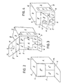
- Figure 2 shows a partial rear perspective view of the container, the back side of the same being partly glued;
- Figure 3 shows a partial front perspective view of the container, the dispensing front side being not glued as yet;
- Figure 4 shows a partial front perspective view of the container with the front side glued in the operative position for employment;
- Figure 5 shows a partial rear perspective view of the container with the back side partly glued.
- Figure 1 shows the semifinished punched box-board for the production of the container-distributor. Said semifinished punched box-board is divided according to well known techniques into five
rectangular zones - The
lower wall 1 has according to the present invention a firstside projecting portion 1′, S, 1˝ and a secondside projecting portion 1˝′ which is separated from said wall by the impressed folding line c while the first portion is separated from said wall the impressed line b. The central stripe S of the first side projecting portion is separated from thezones - The
first side wall 2 has an oblong or elongated window F which is closed by a transparent material as for instance cellophane, a first side projection portion II having aright lobe 2′ and aleft lobe 2˝, which is longer than the right lobe by a length corresponding to half the width of the zone S of the first side projecting portion of thelower wall 1. Thewall 2 has in addition a secondside projecting portion 2˝′ which is substantially rectangular in shape. An area A′ is left free between thelobes 2′ and 2˝. - Said side projecting portions are separated from the
side wall 2 by means of the impressed folding lines e and f. - The
zone 3, which forms the upper wall of the container-distributor also has a first side projecting portion which is made up of theparts 3′ and 3˝ divided from one another by an impressed folding line z, and a secondside projecting portion 3˝′, at a position opposite to that of the first one, said projecting portions being separated from thewall 3 by means of the folding lines h and i, respectively, said lines being cut into the material itself. Theouter part 3′ of the first side projecting portion has a central area L which is defined by a straight line n and by an arc-shaped punched line n′, said area L being intended for forming the catch tab for lifting or lowering thesame zone 3′, which is intended for forming the small front cover of the container. - The sum of the lengths of the projecting
portion 1˝′ and 3˝ corresponds to the width of thezones - Finally, the
second sides wall 4 shows in a way which is fully similar to that of the first side wall 2 a first side projecting portion IV having twolobes 4′ and 4˝, thelobe 4˝ being longer than thelobe 4′ by a length corresponding to half the width of the stripe S of the first side projecting portion of thelower wall 1. Theside wall 2 has a second oppositeside projecting portion 4˝′, which is identical with the secondside projecting portion 2˝′ of thefirst side wall 2. Said side projecting portions are separated from thewall 4 through the impressed folding lines l and m respectively. The folding line k separates thewall 4 from saidgluing zone 5. - As shown in Figure 1, the side edges of the projecting portions of the second and of the
fourth zone zones - In order to build the container, said semifinished punched box-board is folded along the line a, lifting the
wall 2 towards the vertical position and next it is folded along the line d, arranging horizontally theupper wall 3, then it is folded along the line g, folding vertically at the lower position theside wall 4, and finally the box-board is folded along the line k, so as to arrange thezone 5 on the inner surface of thelower wall 1 and to glue it on the same, so that the folding line k coincides with the outer edge of thelower wall 1. Thus a tubular member of square cross-section is obtained in a way that is already well known in the art. - The side edges of the two projecting
portions 1′-S-1˝ of thefirst zone 1 of theouter part 3′ of the third zone are slightly converging and they are blunt-connected with the outer edges w and v. Moreover, the sum of the lenghts of said two projecting portions is slightly larger than the height of theside wall 2, in order to allow the outer edge of the projectingportion 3′-3˝ to be inserted under the outer edge w of the projectingportion 1′-S-1˝. - As can be observed in Figure 2, the back wall of the container is obtained by folding towards the inside space the projecting
portions 2˝′ and 4˝′ along the lines f and m respectively, said projecting portions so becoming arranged vertically on the same plane, the upper projectingportion 3˝′ and thelower projecting portion 1˝′ being glued on both said projecting portions. The sum of the lengths of the projectingportions 2˝′ and 4˝′ is equal to the length of thewalls walls - As can be observed in Figure 3, the side projecting portions II and IV, after being folded inwards along the lines e, l, have their
lobes 2′, 2˝ and 4′, 4˝ on the same plane. Thezone 3˝ of theside projecting portion 3′, 3˝ is then glued on thelobes 2˝ and 4˝, which are in contact with one another, whereas thezones 1˝ and 1′ of the first side projecting portions of thelower wall 1 are respectively glued on thelobes 2′ and 4′. Thus the punched stripe S is above the free zone Z formed between thelobes 2′ and 4′, which as already mentioned above are of sizes less than those of thelobes 2˝ and 4˝. - The access opening A (A′+A˝) is formed between the side projecting portions II and IV, and between the
lobes 2′, 2˝ and 4′, 4˝, said opening being intended for taking the paper serviettes out of said container-distributor. - Finally, the outer edge v of the
zone 3′, which is of suitable sizes to that aim, is inserted under the outer edge w of theside projecting portion 1′,S,1′, so closing the container which is now ready for employment. - The way said container-distributor according to this invention is employed will be disclosed now with reference to the enclosed Figure 4. In order to have access to the paper serviettes stored within said container-distributor, the
zone 3′ is lifted by means of the tab L which is separated from thezone 3′ along the punched line n′ but keeps joined to said zone along the line n, and so the outer edge v of thezone 3′ is removed from its position under the edge w of thezones 1′, S and 1˝, and thezone 3˝ is folded at the upper position along the horizontal line z, which is purposely cut into the material between thezone 3˝ and thezone 3′. - Now the paper serviettes placed within said container-distributor can be taken out of the same through the opening A existing between the
zones 2′, 2˝ and 4′, 4˝. The level of the paper serviettes within said container-distributor can be visually observed through the small window F, above which a transparent material as for instance cellophane is glued internally. When that level goes below the edge w of thezone 1′, S, 1˝, the zone S becomes separated along the two punched lines s from thezones 1′ and 1˝ so creating the space Z which is sufficient to take the paper serviettes which are available at that time out of the container-distributor itself. When the last serviette has also been taken out, the container is thrown away and another one is replaced for the same. - Accordingly, it is evident that this simple container-distributor can be employed cheaply and in a hygienic way both in public premises and in private homes.
- This invention has been disclosed with reference to a preferred embodiment of the same, but it is to be understood tha modifications and changes can be introduced in the same without departing from the spirit and scope of the invention for which a priority right is claimed.
Claims (6)
- A semifinished punched box-board for the production of a container-distributor of paper serviettes, envelopes, cards and the like, said box-board comprising five rectangular adjacent zones which are separated from one another by folding lines, the first four zones forming the walls of said container-distributor while the fifth wall forms the stripe to be glued on the inner portion of the first zone so as to form a tubular member of rectangular cross-section, said semifinished punched box-board being characterized in that:
the first zone (1) and the third zone (3) each one have a projecting portion (1˝′ and 3˝′) on the first side edge (c, i), the sum of the lengths of said projecting portions corresponding to the width of the secondo or of the fourth zone (2, 4);
the second zone (2) and the fourth zone (4) each one have a projecting portion (2˝′ and 4˝′) on the first side edge, the sum of the lenghts of such projecting portions corresponding to the width of the first or the third zone (1 or 3);
the first zone (1) has on its second side edge (b) a projecting portion (1′S1˝) having a central portion (S) which is separated from the side portions (1′ and 1˝) by punched lines (3);
the third zone (3) has on its second side edge (h) a projecting portion which is made up of two parts (3′, 3˝), the outer portion (3′) of such projecting portion having a central portion (L) which is limited by a folding line (n) and by an arc-shaped punched line (n′), said outer portion (3′) being separated through a folding line (z) from the inner portion (3˝);
the second zone (2) and the fourth zone (4) have on their second narrower edge (and respectively 1) a projecting portion which is made up of two marginal lobes (2′, 2˝, respectively 4′, 4˝) which are connected to one another by a central thinner part (II, IV) which borders on the edge (e, 1), the marginal lobes (2˝, respectively 4˝) which are adjacent to the projecting portion (3′, 3˝) being longer than the marginal lobes (2′, respectively 4′) by a lenght corresponding to half the width of the central portion (S) of the projecting portion (1′-S1˝);
all said side projecting portions of the zones (1, 2, 3, 4) being foldable along said side edges of said zones (1, 2, 3, 4), said side edges being formed by the folding lines cut into the material itself. - A semifinished punched box-board according to claim 1, characterized in that an along or elongated opening (F) is provided in the second zone (2), said zone being intended for forming one of the two side walls of said container-distributor.
- A semifinished punched box-board according to claim 1, characterized in that the side edges of the projecting portion of the first zone (1) and those of the outer portion (3′) of the projecting portion of the third zone (3) are slightly converging and they are blunt-connected with the respective outer edges, while the side edges of the inner portion (3˝) of the third zone (3) are parallel to one another.
- A semifinished punched box-board according to claim 1, characterized in that the side edges of the projecting portions of the second and the fourth zone (2, 4) are slightly apart from the side edges of the projecting portions of the first and the third zone (1, 3).
- A semifinished punched box-board according to claim 1, characterized in that the lenghts of the projecting portions (1˝′, 3˝′) of the first and the third zone (1, 3) are equal to half the width of the second or of fourth zone (2 or 4).
- A semifinished punched box-board according to claim 1, characterized in that the lenght of the projecting portions (2˝′, 4˝′) of the second and fourth zone (2, 4) corresponds to half the width of the first or of the third zone (1, 3).
Applications Claiming Priority (2)
| Application Number | Priority Date | Filing Date | Title |
|---|---|---|---|
| IT4808390 | 1990-06-20 | ||
| IT048083A IT9048083A1 (en) | 1990-06-20 | 1990-06-20 | DIE CUT FOR THE PRODUCTION OF A CONTAINER-DISTRIBUTOR FOR PAPER NAPKINS, ENVELOPES, CARDBOARDS AND SIMILAR |
Publications (1)
| Publication Number | Publication Date |
|---|---|
| EP0462947A1 true EP0462947A1 (en) | 1991-12-27 |
Family
ID=11264428
Family Applications (1)
| Application Number | Title | Priority Date | Filing Date |
|---|---|---|---|
| EP91830272A Withdrawn EP0462947A1 (en) | 1990-06-20 | 1991-06-19 | Blank for making a container for dispensing paper serviettes, envelopes, cards or the like |
Country Status (2)
| Country | Link |
|---|---|
| EP (1) | EP0462947A1 (en) |
| IT (1) | IT9048083A1 (en) |
Cited By (3)
| Publication number | Priority date | Publication date | Assignee | Title |
|---|---|---|---|---|
| FR2707827A1 (en) * | 1993-07-15 | 1995-01-20 | Schlumberger Ind Sa | Card distribution set. |
| US5813597A (en) * | 1996-10-15 | 1998-09-29 | Ethicon Endo-Surgery, Inc. | Dual orientation dispenser carton |
| TWI781615B (en) * | 2020-11-17 | 2022-10-21 | 南韓商Cj第一製糖股份有限公司 | Interlocking structure of bottom surface portion of paper box |
Citations (4)
| Publication number | Priority date | Publication date | Assignee | Title |
|---|---|---|---|---|
| LU28925A1 (en) * | ||||
| US2670027A (en) * | 1951-02-03 | 1954-02-23 | Wilferd C Gigler | Machine for sealing cartons |
| US4566607A (en) * | 1984-05-24 | 1986-01-28 | Smith David L | Bag dispenser |
| US4801080A (en) * | 1986-11-19 | 1989-01-31 | Deutchcube, Inc. | Ice cream carton |
-
1990
- 1990-06-20 IT IT048083A patent/IT9048083A1/en unknown
-
1991
- 1991-06-19 EP EP91830272A patent/EP0462947A1/en not_active Withdrawn
Patent Citations (4)
| Publication number | Priority date | Publication date | Assignee | Title |
|---|---|---|---|---|
| LU28925A1 (en) * | ||||
| US2670027A (en) * | 1951-02-03 | 1954-02-23 | Wilferd C Gigler | Machine for sealing cartons |
| US4566607A (en) * | 1984-05-24 | 1986-01-28 | Smith David L | Bag dispenser |
| US4801080A (en) * | 1986-11-19 | 1989-01-31 | Deutchcube, Inc. | Ice cream carton |
Cited By (4)
| Publication number | Priority date | Publication date | Assignee | Title |
|---|---|---|---|---|
| FR2707827A1 (en) * | 1993-07-15 | 1995-01-20 | Schlumberger Ind Sa | Card distribution set. |
| EP0637903A1 (en) * | 1993-07-15 | 1995-02-08 | Schlumberger Industries | Assembly for card distribution |
| US5813597A (en) * | 1996-10-15 | 1998-09-29 | Ethicon Endo-Surgery, Inc. | Dual orientation dispenser carton |
| TWI781615B (en) * | 2020-11-17 | 2022-10-21 | 南韓商Cj第一製糖股份有限公司 | Interlocking structure of bottom surface portion of paper box |
Also Published As
| Publication number | Publication date |
|---|---|
| IT9048083A0 (en) | 1990-06-20 |
| IT9048083A1 (en) | 1991-12-21 |
Similar Documents
| Publication | Publication Date | Title |
|---|---|---|
| CN102056813B (en) | Sliding-action hinged-lid package | |
| US5341952A (en) | Rigid container for interchangeable flexible packs | |
| EP0587132A1 (en) | Decahedral tissue carton | |
| JP4011542B2 (en) | Box with lid | |
| RU2242414C2 (en) | Rigid cigarette box partly opened for demonstration its content | |
| KR101355762B1 (en) | Hinge-lid container with additional integral panels | |
| CN102046478A (en) | Sliding-action hinged-lid package | |
| MX2013014798A (en) | Container and lifting means for an article. | |
| GB1584066A (en) | Boxes and blanks therefor | |
| US11111052B2 (en) | Dual cell, efficient box with top slide openings and view windows | |
| JP2006056603A (en) | Package for slender tobacco articles | |
| US2339383A (en) | Dispensing carton | |
| US2287420A (en) | Paper sheet dispensing carton | |
| EP0323596A1 (en) | Sealable dispenser, provided with overturning cover, for dispensing paper napkins or the like articles | |
| US2000454A (en) | Toilet paper container and dispenser | |
| US3127083A (en) | Dispensing carton | |
| US2407415A (en) | Dispensing package | |
| EP3137386B1 (en) | Carton, carton blank and method of erecting and filling the carton | |
| EP0462947A1 (en) | Blank for making a container for dispensing paper serviettes, envelopes, cards or the like | |
| US10343810B1 (en) | Tissue carton | |
| US2326527A (en) | Carton construction | |
| JPH04501099A (en) | Container for filling substances into film bags | |
| US1989806A (en) | Packet dispensing device | |
| EP0710609A1 (en) | A cigarette packet with a hinged lid | |
| US2034885A (en) | Folding carton |
Legal Events
| Date | Code | Title | Description |
|---|---|---|---|
| PUAI | Public reference made under article 153(3) epc to a published international application that has entered the european phase |
Free format text: ORIGINAL CODE: 0009012 |
|
| AK | Designated contracting states |
Kind code of ref document: A1 Designated state(s): CH DE ES FR GR LI |
|
| 17P | Request for examination filed |
Effective date: 19920505 |
|
| 17Q | First examination report despatched |
Effective date: 19940331 |
|
| STAA | Information on the status of an ep patent application or granted ep patent |
Free format text: STATUS: THE APPLICATION IS DEEMED TO BE WITHDRAWN |
|
| 18D | Application deemed to be withdrawn |
Effective date: 19941005 |