EP0462092B1 - Verfahren und Vorrichtung in einer Kompakt-Presspartie einer Papiermaschine - Google Patents
Verfahren und Vorrichtung in einer Kompakt-Presspartie einer Papiermaschine Download PDFInfo
- Publication number
- EP0462092B1 EP0462092B1 EP91850165A EP91850165A EP0462092B1 EP 0462092 B1 EP0462092 B1 EP 0462092B1 EP 91850165 A EP91850165 A EP 91850165A EP 91850165 A EP91850165 A EP 91850165A EP 0462092 B1 EP0462092 B1 EP 0462092B1
- Authority
- EP
- European Patent Office
- Prior art keywords
- frame part
- press
- rolls
- roll
- intermediate frame
- Prior art date
- Legal status (The legal status is an assumption and is not a legal conclusion. Google has not performed a legal analysis and makes no representation as to the accuracy of the status listed.)
- Expired - Lifetime
Links
- 238000000034 method Methods 0.000 title claims abstract description 15
- 239000004744 fabric Substances 0.000 claims abstract description 55
- 230000003068 static effect Effects 0.000 claims abstract description 3
- 238000010276 construction Methods 0.000 claims description 21
- 230000001360 synchronised effect Effects 0.000 claims description 2
- 238000001035 drying Methods 0.000 description 3
- 230000001627 detrimental effect Effects 0.000 description 2
- 238000006073 displacement reaction Methods 0.000 description 2
- 230000000694 effects Effects 0.000 description 2
- 239000011230 binding agent Substances 0.000 description 1
- 238000012986 modification Methods 0.000 description 1
- 230000004048 modification Effects 0.000 description 1
- 230000010363 phase shift Effects 0.000 description 1
Images


Classifications
-
- D—TEXTILES; PAPER
- D21—PAPER-MAKING; PRODUCTION OF CELLULOSE
- D21F—PAPER-MAKING MACHINES; METHODS OF PRODUCING PAPER THEREON
- D21F3/00—Press section of machines for making continuous webs of paper
- D21F3/02—Wet presses
- D21F3/04—Arrangements thereof
Definitions
- the invention concerns a method in a compact press section of a paper machine for balancing of its static and dynamic properties as well as for replacing of the press rolls and fabrics, in which press section the press rolls form a compact combination of rolls, the space in and above said combination of rolls, placed between the front and rear frame parts of the press section, being opened and closed, and by means of which said space at least the upper fabrics and the upper press rolls in the press section are replaced by means of a crane mounted on the ceiling or equivalent, preferably substantially by direct raising and lowering, said front and rear frame parts being interconnected rigidly at and above the press roll combination by means of a rigid intermediate frame part.
- the invention concerns a frame construction of a compact press section, comprising a front frame part and a rear frame part, certain press rolls in the press section being supported in connection with said front frame part, and at least the press rolls of the last nip or of the latter nips in the press section being supported in connection with said rear frame part, an openable space remaining between said frame parts, through which space the press rolls in the compact combination of rolls can be replaced substantially by raising and lowering, the press frame construction comprising an intermediate frame part.
- vanous compact and closed press sections which include a combination of press rolls, whose press rolls form, as a rule, at least three press nips with each other.
- press rolls whose press rolls form, as a rule, at least three press nips with each other.
- the first twin-felt nip is formed between a hollow-faced lower press roll and an upper press-suction roll, said suction roll forming a second nip with the smooth-faced centre roll of the press, a third press nip being also formed in connection with said centre roll.
- the first twin-felt horizontal nip is formed between a lower hollow-faced roll and an upper press-suction roll, after which the web follows the upper fabric as a vertical run into a second nip, which is formed between a hollow-faced press roll separate from the rolls of the first nip and the smooth-faced centre roll; in connection with said centre roll, a third press nip, which is provided with a felt, is formed by means of a hollow-faced press roll.
- vibrations in its frame are formed in the press nips, and they cause variations in the linear loads in the nips, which has a direct detrimental effect on the quality of the paper that is being produced.
- the vibrations in a press frame are particularly awkward when the vibrations and displacements at the operation side and at the driving side of the frame are of different magnitudes and/or have a phase shift in relation to each other.
- the main object of the present invention is to provide a press frame construction of a compact press section which is both statically and dynamically better balanced than in prior art.
- An object of the invention is to provide solutions for the problems discussed above so that replacements of the press rolls and fabrics in a compact press section can be carried out advantageously and rapidly in spite of a rigid press frame system.
- said pick-up felt must also act as a press felt both in the first press nip and in the second press nip.
- the method of the invention is mainly characterized in that said intermediate frame part is arranged to operate as the frame part of the tensioning device of the first upper fabric, that said intermediate frame part, together with the upper-fabric tensioning device and the tensioning roll, is pivoted around horizontal articulated joints, which connect it to the front frame part, or is shifted to the side substantially in a linear way, so that at and above the press roll combination a free open space is opened, which can be utilized in replacement both of the upper press rolls and of the upper fabrics.
- the press section in accordance with the invention is mainly characterized in that the intermediate frame part is coupled in connection with the front frame part by means of horizontal articulated joints or by means of corresponding linear guides from above the compact press roll combination, that means for tensioning of the first upper fabric are fitted on said intermediate frame part, that the intermediate frame part can be attached to the rear frame pant by means of rigid joints, and that the intermediate frame part is formed as a rigid unit by means of a transverse support beam or equivalent interconnecting its side parts.
- the front and rear frames of the press frame construction can be balanced both statically and dynamically.
- the upper felt tensioning roll and the felt tensioning device can be placed at and above the press roll combination, for the pick-up roll, which acts as a press felt in the first nip and in the second nip, an increased length and service life are obtained, whereby the interval of replacement of said fabric can be made substantially longer.
- the tending platforms with their handrails can be connected with the combined felt tensioning arrangement and pivotal intermediate frame part, whereby these tending platforms can also be brought out of the way for replacement of rolls and felts without separate operations of disassembly.
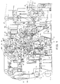
- Figure 1 is a schematic side view of a "Sym-Press 0" press frame construction in accordance with the invention and of a compact press roll combination placed in connection with said frame construction.
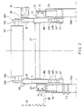
- Figure 2 is a sectional view taken along the line II-II in Fig. 1.
- Figure 3 shows a "Sym-Press 0" press section as shown in Figs. 1 and 2 with the press frame in the open position and while the upper press rolls are being replaced as well as after the first upper fabric has been removed.
- Figure 4 shows, in a way corresponding to Fig. 3, the press frame in the open position while the centre roll in the combination of rolls and the first upper fabric are being replaced.
- the frame construction of the "Sym-Press 0" press section shown in Figs. 1 to 4 comprises a front frame pant 50a, a lower intermediate frame part 50b, and a rear frame part 50c. Between the front frame part 50a and the rear frame part 50c, there is an openable space T, which is utilized for replacement both of the fabrics 10 and 20 and of the press rolls 15,16,17 and 18.
- the frame parts 50a and 50c are interconnected, by their top portions, by means of a special intermediate frame part 60 in accordance with the present invention, which frame pant 60 is, by one end, linked in connection with the front frame 50a by means of horizontal articulated joints 61 and which frame part 60 can be locked, by the opposite end, by means of rapid connectors 64, in connection with the top portion of the rear frame part 50c.
- first upper fabric 10 onto which the paper web W to be dewatered in the press section is transferred from the forming wire 11 by means of the suction zone 12a of the pick-up roll 12 and on which fabric 10 the web W is carried into the first and the second nip N1 and N2.
- the web W is transferred on the lower face of the upper fabric 10 into the first nip N1, which is formed between a hollow-faced lower press roll 14 and an upper press-suction roll 15.
- a lower fabric 13 runs through the nip N1, from which fabric 13 the web W is separated after the first nip N1 by the effect of the suction zone 15a of the suction roll 15.
- the web W follows the first fabric 10 and is passed on the vertical straight run of the fabric 10 into the second nip N2.
- the second nip N2 is formed between a hollow-faced press roll 16 and the smooth-faced 17' centre roll 17 of the press.
- the suction roll 15 is supported on bearing supports 48a, which are connected to the projection pant 52 of the front frame 50a by means of articulated joints 48b.
- the first nip N1 can be loaded and opened by means of hydraulic cylinders 48c fitted between the front frame 50a and the bearing supports 48a.
- the web W, adhering to the smooth face 17' of the centre roll 17, follows said roll into the third nip N3, which is formed between the centre roll 17 and a hollow-faced press roll 18.
- the third nip N3 the second upper fabric 20 runs, whose guide roll, which is placed above the roll combination, is denoted with the reference numeral 20a.
- the press roll 18 is mounted on bearing supports 49a, which are linked by means of articulated joints 49b in connection with the rear frame 50c.
- the third nip N3 can be opened and loaded by means of hydraulic cylinders 49c.
- the web W is detached from the centre roll 17 and, being guided by the guide roll 22, is transferred onto the transfer-suction roll 23, over which a lower fabric 21 runs.
- the web W is transferred into a separate fourth nip N4 in the press section, which nip is formed between an upper smooth-faced 24' roll 24 and a lower hollow-faced roll 25.
- the web W is detached and transferred onto the drying wire 26, which carries the web W into the drying section (not shown).
- a particular openable intermediate frame part 60 is fitted, which is shown in Fig. 1 in the closed position 60A as well as, by dashed lines, in the open position 60B.
- said intermediate frame part 60 interconnects the front frame part 50a and the rear frame part 50c of the press so that vibrations of the press frames can be reduced as well as so that the vibrations are of the same phase and of equal magnitudes at the operation side and at the driving side of the machine.
- the location of the intermediate frame part 60 is also advantageous in the respect that the frame part is placed as high as possible and far from the largest vibrating masses.
- the intermediate frame pant 60 is, at the same time, fitted to operate as the frame part of the tensioning means for the press and pick-up fabric 10.
- the felt 10 tensioning device 65 is placed on the intermediate frame part 60, which tensioning device 65 is arranged to move, by means of a drive gear, in its guides 68 parallel to the machine direction.
- a tensioning roll 34 for the pick-up felt 10 is mounted, the outer extreme position of said roll being denoted with the reference numeral 34'.
- the upper-felt 10 tensioning roll 34 can be placed at and above the press roll combination 14,15,16,17 and 18, for which reason the length of the upper felt 10 can be increased substantially.
- the frame part 60 is connected to flange parts 62, which are placed both at the operation side and at the driving side of the machine and by whose intermediate the frame part 60 is linked with the front frame part 50, both at the operation side and at the driving side of the machine, by means of horizontal pivot shafts 61, from underneath the frame part 60.
- the hydraulic cylinders 63 are connected to said projection parts 62a and 62b by means of articulated joints 63a.
- the intermediate frame pant 60 and the felt tensioning means are provided with guides 68, on which the felt tensioning devices 65 are supported to be shifted by means of a tensioning motor 66.
- the felt tensioning devices 65 are connected with the bearing supports 69a and 69b of the axle journals 34a and 34b of the tensioning roll 34.
- flange parts 71 in connection with the side frames of the intermediate frame part 60 both at the operation side and at the driving side of the machine.
- One flange part 71 is fixed to the front frame 50a, and the other flange part 71 is fixed outside the side frames of the intermediate frame pant 60.
- the flange parts 71 are provided with recesses 72, and the intermediate frame part 60 can be fixed very rigidly in connection with the front frame part 50a by means of eyebolts 73 fitted into said recesses 72.
- the intermediate frame part 60 is very rigid, partly because of its transverse beam 67, so that the intermediate frame part 60 vibrates both at the operation side and at the driving side of the machine at the same rate and with the same amplitude.
- the rigidity of the whole frame 50,60 is also increased by the robust joints 64 and 71.
- Fig. 2 the tending platforms 80 and their handrails 81 at the operation side of the machine are shown schematically by means of dashed lines.
- the tending platforms 80 are attached to the side part of the intermediate frame part 60 so that the tending platforms 80 with their handrails 81 are shifted at the same time out of the opened space T and out of the way for replacement of rolls when the intermediate frame part 60 is pivoted to the opened position 60B.
- the intermediate frame part 60A closed by means of the pair of hydraulic cylinders 63 can be pivoted to the opened position 60B shown in Fig. 3, whereby the parts 64A and 64B of the rapid connector 64 are separated from each other, and an open free space T is opened above the press roll combination 14,15,16,17,18.
- This space T is advantageously available for quick replacement of the press fabrics 10 and 20 as well as of the press rolls 15,16,17,18, in the way that will come out later.
- the mechanism 30 for opening and loading of the press roll 16 which mechanism will be called the support mechanism in the following, for the sake of conciseness, comprises bearing supports 46, which are fixed to the side frames of the support mechanism 30.
- the mechanism 30 is linked in connection with the projection part 51 of the front frame part 50a by the ends of the projection parts of the side frames 32 by means of articulated joints 33.
- the mechanism 30 includes an L-section connecting beam 35, which is fixed between the side frames 32.
- a rigid support mechanism 30 is formed, which is pivoted around the articulated joints 33 by means of a pair of hydraulic cylinders 31.
- a splash plate 40 is attached, which is placed above the suction roll 15 and gives protection against splashes coming from said roll.
- the support mechanism 30 is shown in its first, slightly opened position 30B, in which the nip N2 is open and the roll 16 is in the position 16B.
- the shifting between the positions 16A and 16B takes place by means of the pair of hydraulic cylinders 31 by pivoting the support mechanism 30.
- the support mechanism 30 can be locked in its position 30B shown in Fig. 4, e.g., by means of locking pins.
- Fig. 1 shows the operation position of the press section, wherein the nips N1,N2,N3 and N4 are loaded by their actuators with certain linear loads and dewater the web W.
- the fourth nip N4 is not always necessary, but the web W may be passed from the centre roll 17 directly into the drying section.
- the centre roll 17 can be replaced by means of a pair of lifting cables 42 and a crane mounted on the ceiling by direct raising through the opened space T between the frame parts 50a and 50c, because the opened intermediate frame part 60B is not in its way.
- the upper roll 18A of the third nip N3 can also be replaced by means of lifting cables 41 and a ceiling crane (not shown) in the paper machine hall.
- Fig. 4 the second open position 30C of the support mechanism 30 is shown, in which position the mechanism is fully opened, in which case the press roll 16 is in the position 16C.
- the mechanism 30 is supported in the open position 30C shown in Fig. 4 by means of locking pins and holes provided in connection with its side frames 32 and the projection part 51.
- the splash plate is also shifted to the position 40C, where it is not in the way for replacement of the suction roll 15a.
- the suction roll 15a of the first nip N1 can be replaced by means of the ceiling crane by using a pair of lifting cables 43 after the centre roll 17 has first been removed by means of a pair of lifting cables 42.
- the lower press roll 14 in the first nip N1 which is mounted on stationary bearing supports 27, can be replaced by means of a carriage 47 by shifting it in its axial direction and while supporting and shifting the outer, operation-side end of the roll 14 by means of a cable attached to a crane.
- the intermediate frame part 60 is pivoted from the opened position 60B shown in Fig. 4 to the closed position 60A shown in Fig. 1, in which position 60A it is locked by means of the rapid connectors 71 and 64 both from the operation side and from the driving side of the machine.
- the front frame part 50a and the rear frame part 50c can be connected as far away as possible from the largest vibrating masses so that the frame becomes very rigid and that the frame vibrates synchronously at its operation side and driving side with a little amplitude.
- such a preferred embodiment of the invention is illustrated in which the openable intermediate frame part 60 with the felt tensioning means is linked pivotally in connection with the front frame part 50a.
- the invention can, however, also be carried into effect so that the intermediate frame part 60 is made into a carriage-like construction, which is supported on glide guides or on rails and wheels to be shifted onto the front frame part 50a manually or, preferably, by means of mechanized actuators to the open and closed position and which can be locked rigidly into a closed position on the compact combination of rolls.
- One alternative embodiment of the invention which is usually, however, not an optimal one, is a system in which the intermediate frame part 60 can be shifted into the open position along linear guides onto the rear frame part 50c. However, before such a shifting, as a rule, the second upper fabric 20 must be removed.
Landscapes
- Paper (AREA)
- Press Drives And Press Lines (AREA)
- Saccharide Compounds (AREA)
- Measuring Or Testing Involving Enzymes Or Micro-Organisms (AREA)
Claims (10)
- Verfahren in einer Kompakt-Pressenpartie einer Papiermaschine für das Ausgleichen ihrer statischen und dynamischen Eigenschaften sowie für das Austauschen der Preßwalzen und -Siebtücher, wobei in der Pressenpartie die Preßwalzen eine Kompakt-Kombination von Walzen bilden, wobei ein sich zwischen den vorderen und hinteren Gerüstteilen (50a, 50c) der Pressenpartie befindlicher Raum (T) in und über der Kombination von Walzen geöffnet und geschlossen wird, wobei mit Hilfe des Raumes (T) zumindest die oberen Siebtücher (10, 20) und die oberen Preßwalzen (15, 16, 17, 18) in der Pressenpartie mit Hilfe eines an der Decke oder dergleichen montierten Kranes ausgetauscht werden, und zwar vorzugsweise im wesentlichen durch unmittelbares Anheben und Absenken, wobei die vorderen und hinteren Gerüstteile (50a, 50c) mit Hilfe eines starren Zwischengerüstteils (60) an und über der Preßwalzenkombination starr miteinander verbunden sind, dadurch gekennzeichnet, daß der Zwischengerüstteil (60) angeordnet ist, um als Gerüstteil der Spannvorrichtung des ersten oberen Siebtuchs (10) zu wirken, daß der Zwischengerüstteil (60) zusammen mit der Spannvorrichtung für das obere Siebtuch (10) und der Spannwalze (34) um horizontale drehgelenkige Verbindungen (61) geschwenkt wird, welche ihn an den vorderen Gerüstteil (50a) verbinden, oder im wesentlichen auf linearem Wege zur Seite verstellt wird, so daß an und über der Preßwalzenkombination (14, 15, 16, 17, 18) der freie offene Raum (T) geöffnet ist, welcher beim Austausch von sowohl der oberen Preßwalzen (15, 16, 17, 18) als auch der oberen Siebtücher (10, 20) verwendet werden kann.
- Verfahren nach Anspruch 1, dadurch gekennzeichnet, daß der Zwischengerüstteil (60) in seiner geschlossenen Position an dem vorderen Gerüstteil (50a), und zwar, außer mit Hilfe der Schwenkverbindung (61) oder dergleichen, mit Hilfe von starren öffenbaren Flanschverbindungen (71), und an dem hinteren Gerüstteil (50c) angebracht ist, vorzugsweise an dem Außenende des Vorsprungsteils (66) in seinem Oberabschnitt, und zwar mit Hilfe von starren öffenbaren Flanschverbindungen (64).
- Verfahren nach Anspruch 1 oder 2, dadurch gekennzeichnet, daß die an die Filzspanneinrichtung an dem Zwischengerüstteil (60) befestigte Spannwalze (34) an und über der Kompakt-Kombination von Walzen (14, 15, 16, 17, 18) angeordnet ist, so daß die Länge und dadurch die Beständigkeit und das Austauschintervall des ersten oberen Siebtuchs (10) verlängert werden, welches sowohl als Aufnahmesiebtuch als auch als Preßsiebtuch in den ersten und zweiten Preßkniffen (N₁, N₂) in der Pressenpartie wirkt.
- Verfahren nach einem der Ansprüche 1 bis 3, dadurch gekennzeichnet, daß bei dem Verfahren die an und über der Kombination von Preßwalzen (14, 15, 16, 17, 18) angeordnete vorderste Leitwalze (20a) des zweiten oberen Siebtuchs (20) in seinem Halteplatz (20A) aus dem Austauschweg von Walzen verstellt ist.
- Verfahren nach einem der Ansprüche 1 bis 4, dadurch gekennzeichnet, daß die Preßwalze (16), die mit der glattflächigen Mittelwalze (17) den zweiten Preßkniff (N₂) bildet, auf einem derartigen Öffnungs- und Lademechanismus (30) gestützt ist, an dem Stellglieder, wie etwa hydraulische Zylinder (31), verbunden sind, wobei mit Hilfe der Stellglieder sowohl der zweite Kniff (N₂) mit einer geeigneten Linearlast belastet wird als auch der Mechanismus (30) zu einer Offenposition oder zu Offenpositionen (30B, 30C) geschwenkt wird, und daß die Bewegungen der Seitenteile des Mechanismus (30) mit Hilfe eines zwischen diesen angebrachten Verbindungsteils (35) miteinander synchronisiert sind.
- Gerüstkonstruktion einer Kompakt-Pressenpartie nach einem der Ansprüche 1 bis 5, mit einem vorderen Gerüstteil (50a) und einem hinteren Gerüstteil (50c), wobei bestimmte Preßwalzen (15, 16) in der Pressenpartie in Verbindung mit dem vorderen Gerüstteil (50a) gestützt sind, wobei zumindest die Preßwalzen (18, 28, 25) des letzten Kniffes oder der letzten Kniffe (N₃, N₄) in der Pressenpartie in Verbindung mit dem hinteren Gerüstteil (50c) gestützt sind, wobei ein öffenbarer Raum (T) zwischen den Gerüstteilen (50a, 50c) verbleibt, durch welchen Raum die Preßwalzen (15, 16, 17, 18) in der Kompakt-Kombination von Walzen im wesentlichen durch Anheben und Absenken ausgetauscht werden können, wobei die Preßgerüstkonstruktion einen Zwischengerüstteil (60) aufweist, dadurch gekennzeichnet, daß der Zwischengerüstteil in Verbindung mit dem vorderen Gerüstteil (50) mit Hilfe von horizontalen drehgelenkigen Verbindungen (61) oder mit Hilfe entsprechender Linearführungen von oberhalb der Kompakt-Preßwalzenkombination (14, 15, 16, 17, 18) gekoppelt ist, daß eine Einrichtung (34, 35, 66, 68) zum Spannen des ersten oberen Siebtuchs (10) an dem Zwischengerüstteil (60) befestigt ist, daß der Zwischengerüstteil (60) mit Hilfe starrer Verbindungen (64) an dem hinteren Gerüstteil (50c) befestigt ist und daß der Zwischengerüstteil (60) mittels eines Querstützbalkens (67) oder dergleichen, der seine Seitenteile (68a, 68b) miteinander verbindet, als starre Einheit gebildet ist.
- Preßgerüstkonstruktion nach Anspruch 6, dadurch gekennzeichnet, daß die Seitengerüste (68a, 68b) des Zwischengerüstteils (60) mit nach unten gerichteten Vorsprungsteilen (62a, 62b) verbunden sind, daß die horizontalen drehgelenkigen Verbindungen (61) in Verbindung mit den unteren Enden der Vorsprungsteile (62a, 62b) angeordnet sind und daß der Oberabschnitt des Zwischengerüstteiles (60) mit Führungen (68) versehen ist, auf welchen die Lagerstützen (69a, 69b) der Spannwalze (34) des oberen Siebtuchs (10) in Bearbeitungsrichtung verschiebbar gestützt sind.
- Preßgerüstkonstruktion nach Anspruch 6 oder 7, dadurch gekennzeichnet, daß zwischen dem schwenkbaren oder linear verschiebbaren Zwischengerüstteil (60) und dem vorderen Gerüstteil (60a) Stellglieder angebracht sind, vorzugsweise ein Paar von hydraulischen Zylindern (63), mit deren Hilfe der Zwischengerüstteil (60) zur geöffneten Position (60B) und zurück zur geschlossenen Position (60A) verstellbar ist.
- Preßgerüstkonstruktion nach einen der Ansprüche 6 bis 8, dadurch gekennzeichnet, daß der Zwischengerüstteil (61) mit Flanschteilen (71) versehen ist, die von seinen Seitengerüsten (68a, 68b) nach außen gerichtet sind, wobei die Seitengerüste (74) des vorderen Gerüstteils (50a) mit entsprechenden Flanschteilen (71) versehen sind, und zwar sowohl an der Arbeitsseite als auch an der Antriebsseite der Maschine, wobei die Flanschteile (71) mit Hilfe von Schnellanschlüssen (72, 73) miteinander verriegelbar sind, um den Zwischengerüstteil (60) mit dem vorderen Gerüstteil (50a) starr zu verbinden, und daß das gegenüberliegende Ende des Zwischengerüstteils (60) mit Flanschteilen (64A) oder dergleichen versehen ist, welche, zusammen mit, in Verbindung mit dem Oberabschnitt des hinteren Gerüstteils (50c) angeordneten Flanschteilen (64B), vorzugsweise mit seinem Vorsprungsteil (66), öffenbare Schnellanschlüsse bilden, mit deren Hilfe der Zwischengerüstteil (60) in seiner geschlossenen Position (60A) an dem hinteren Gerüstteil (50c) starr angebracht ist.
- Preßgerüstkonstruktion nach einem der Ansprüche 6 bis 9, dadurch gekennzeichnet, daß die Spannwalze (34), die über dem Zwischengerüstteil (60) gestützt ist und mit der Einrichtung zum Spannen des ersten oberen Siebtuchs (10) verbunden ist, an und über der Kompakt-Kombination von Preßwalzen (14, 15, 16, 17, 18) angeordnet ist, und zwar im Hinblick darauf, die Länge sowie die Haltbarkeit und die Austauschintervalle des ersten oberen Siebtuchs (10) zu steigern.
Applications Claiming Priority (2)
| Application Number | Priority Date | Filing Date | Title |
|---|---|---|---|
| FI903004A FI85606C (fi) | 1990-06-15 | 1990-06-15 | Foerfarande och anordning i ett kompakt pressparti av en pappersmaskin. |
| FI903004 | 1990-06-15 |
Publications (2)
| Publication Number | Publication Date |
|---|---|
| EP0462092A1 EP0462092A1 (de) | 1991-12-18 |
| EP0462092B1 true EP0462092B1 (de) | 1995-08-09 |
Family
ID=8530638
Family Applications (1)
| Application Number | Title | Priority Date | Filing Date |
|---|---|---|---|
| EP91850165A Expired - Lifetime EP0462092B1 (de) | 1990-06-15 | 1991-06-14 | Verfahren und Vorrichtung in einer Kompakt-Presspartie einer Papiermaschine |
Country Status (6)
| Country | Link |
|---|---|
| US (1) | US5127996A (de) |
| EP (1) | EP0462092B1 (de) |
| AT (1) | ATE126296T1 (de) |
| CA (1) | CA2044458C (de) |
| DE (1) | DE69111913T2 (de) |
| FI (1) | FI85606C (de) |
Family Cites Families (10)
| Publication number | Priority date | Publication date | Assignee | Title |
|---|---|---|---|---|
| FI763434A7 (fi) * | 1976-11-30 | 1978-05-31 | Valmet Oy | Foerfarande i vaotpartiet i en pappersmaskin |
| US4942634A (en) * | 1983-08-31 | 1990-07-24 | Lumex, Inc. | Damped fluid displacement support system and method for making the same |
| US4657634A (en) * | 1984-11-29 | 1987-04-14 | Valmet Oy | Frame construction and method in a paper machine press section for facilitating replacement of press rolls and fabrics |
| FI70951C (fi) * | 1984-11-29 | 1999-05-19 | Valmet Oy | Menetelmä paperikoneen puristinosassa kudosten ja telojen vaihtamiseks i sekä menetelmää soveltava puristinosan runkorakenne |
| US4909905A (en) * | 1986-06-03 | 1990-03-20 | Valmet Paper Machinery Inc. | Closed press section of a paper machine and a frame construction for same |
| FI85997C (fi) * | 1987-06-17 | 1992-06-25 | Valmet Paper Machinery Inc | Presspartiet i en pappersmaskin. |
| JPH07109075B2 (ja) * | 1987-08-21 | 1995-11-22 | 三菱重工業株式会社 | 抄紙機のフレ−ム構造 |
| FI82955C (fi) * | 1987-09-15 | 1992-06-02 | Tampella Oy Ab | Stamkonstruktion foer en pressdel i en pappersmaskin. |
| FI84377C (fi) * | 1988-06-20 | 1991-11-25 | Valmet Paper Machinery Inc | Pressparti med stomkonstruktioner i pappersmaskin. |
| GB8815009D0 (en) * | 1988-06-23 | 1988-07-27 | Beloit Corp | Press apparatus |
-
1990
- 1990-06-15 FI FI903004A patent/FI85606C/fi not_active IP Right Cessation
-
1991
- 1991-06-12 CA CA002044458A patent/CA2044458C/en not_active Expired - Fee Related
- 1991-06-12 US US07/713,806 patent/US5127996A/en not_active Expired - Fee Related
- 1991-06-14 DE DE69111913T patent/DE69111913T2/de not_active Expired - Fee Related
- 1991-06-14 AT AT91850165T patent/ATE126296T1/de not_active IP Right Cessation
- 1991-06-14 EP EP91850165A patent/EP0462092B1/de not_active Expired - Lifetime
Also Published As
| Publication number | Publication date |
|---|---|
| DE69111913D1 (de) | 1995-09-14 |
| FI903004A0 (fi) | 1990-06-15 |
| FI85606C (fi) | 1992-05-11 |
| CA2044458A1 (en) | 1991-12-16 |
| EP0462092A1 (de) | 1991-12-18 |
| US5127996A (en) | 1992-07-07 |
| DE69111913T2 (de) | 1996-01-11 |
| ATE126296T1 (de) | 1995-08-15 |
| CA2044458C (en) | 1999-11-16 |
| FI85606B (fi) | 1992-01-31 |
Similar Documents
| Publication | Publication Date | Title |
|---|---|---|
| US4699692A (en) | Method in a paper machine press section for facilitating replacement of press rolls and fabrics | |
| US4657634A (en) | Frame construction and method in a paper machine press section for facilitating replacement of press rolls and fabrics | |
| US4919762A (en) | Press section and press section/frame construction combination in a paper machine | |
| EP0462092B1 (de) | Verfahren und Vorrichtung in einer Kompakt-Presspartie einer Papiermaschine | |
| CA1326151C (en) | Structural frame for separate nips in a press section | |
| JPH05263822A (ja) | 2つのローラの間の支持結合装置 | |
| US5399242A (en) | Machine frame for supporting dewatering elements | |
| US6136149A (en) | Press section in a paper machine and method for replacing press fabrics therein | |
| FI84377B (fi) | Pressparti med stomkonstruktioner i pappersmaskin. | |
| US5154799A (en) | Method and device in a compact press section of a paper machine for replacement of rolls and fabrics | |
| EP0287544B1 (de) | Ständerkonstruktion für die Presspartie einer Papiermaschine | |
| EP0287542B1 (de) | Ständerkonstruktion für die Presspartie einer Papiermaschine | |
| US7384511B2 (en) | Device for changing the cloth of a paper machine | |
| CA2201668C (en) | Roll press | |
| EP0308029B1 (de) | Rahmenkonstruktion einer Pressenpartie in einer Papiermaschine | |
| US4922990A (en) | Press section frame in a paper machine | |
| CA2124473C (en) | Apparatus for dewatering mixtures of fibrous and liquid materials | |
| EP0224461B1 (de) | Verfahren und Chassis in einer Presspartie einer Papiermaschine zum Erleichtern der Auswechselung von Presswalzen und Filzen | |
| US5577441A (en) | Pressing device for extracting liquid from a pulp web |
Legal Events
| Date | Code | Title | Description |
|---|---|---|---|
| PUAI | Public reference made under article 153(3) epc to a published international application that has entered the european phase |
Free format text: ORIGINAL CODE: 0009012 |
|
| AK | Designated contracting states |
Kind code of ref document: A1 Designated state(s): AT DE FR GB IT SE |
|
| 17P | Request for examination filed |
Effective date: 19911107 |
|
| 17Q | First examination report despatched |
Effective date: 19940923 |
|
| GRAA | (expected) grant |
Free format text: ORIGINAL CODE: 0009210 |
|
| AK | Designated contracting states |
Kind code of ref document: B1 Designated state(s): AT DE FR GB IT SE |
|
| REF | Corresponds to: |
Ref document number: 126296 Country of ref document: AT Date of ref document: 19950815 Kind code of ref document: T |
|
| REF | Corresponds to: |
Ref document number: 69111913 Country of ref document: DE Date of ref document: 19950914 |
|
| ITF | It: translation for a ep patent filed | ||
| ET | Fr: translation filed | ||
| PLBE | No opposition filed within time limit |
Free format text: ORIGINAL CODE: 0009261 |
|
| STAA | Information on the status of an ep patent application or granted ep patent |
Free format text: STATUS: NO OPPOSITION FILED WITHIN TIME LIMIT |
|
| 26N | No opposition filed | ||
| PGFP | Annual fee paid to national office [announced via postgrant information from national office to epo] |
Ref country code: FR Payment date: 20010530 Year of fee payment: 11 |
|
| PGFP | Annual fee paid to national office [announced via postgrant information from national office to epo] |
Ref country code: GB Payment date: 20010613 Year of fee payment: 11 |
|
| PGFP | Annual fee paid to national office [announced via postgrant information from national office to epo] |
Ref country code: SE Payment date: 20010615 Year of fee payment: 11 |
|
| PGFP | Annual fee paid to national office [announced via postgrant information from national office to epo] |
Ref country code: AT Payment date: 20010620 Year of fee payment: 11 |
|
| PGFP | Annual fee paid to national office [announced via postgrant information from national office to epo] |
Ref country code: DE Payment date: 20010730 Year of fee payment: 11 |
|
| REG | Reference to a national code |
Ref country code: GB Ref legal event code: IF02 |
|
| PG25 | Lapsed in a contracting state [announced via postgrant information from national office to epo] |
Ref country code: GB Free format text: LAPSE BECAUSE OF NON-PAYMENT OF DUE FEES Effective date: 20020614 Ref country code: AT Free format text: LAPSE BECAUSE OF NON-PAYMENT OF DUE FEES Effective date: 20020614 |
|
| PG25 | Lapsed in a contracting state [announced via postgrant information from national office to epo] |
Ref country code: SE Free format text: LAPSE BECAUSE OF NON-PAYMENT OF DUE FEES Effective date: 20020615 |
|
| PG25 | Lapsed in a contracting state [announced via postgrant information from national office to epo] |
Ref country code: DE Free format text: LAPSE BECAUSE OF NON-PAYMENT OF DUE FEES Effective date: 20030101 |
|
| EUG | Se: european patent has lapsed | ||
| GBPC | Gb: european patent ceased through non-payment of renewal fee |
Effective date: 20020614 |
|
| PG25 | Lapsed in a contracting state [announced via postgrant information from national office to epo] |
Ref country code: FR Free format text: LAPSE BECAUSE OF NON-PAYMENT OF DUE FEES Effective date: 20030228 |
|
| REG | Reference to a national code |
Ref country code: FR Ref legal event code: ST |
|
| PG25 | Lapsed in a contracting state [announced via postgrant information from national office to epo] |
Ref country code: IT Free format text: LAPSE BECAUSE OF NON-PAYMENT OF DUE FEES;WARNING: LAPSES OF ITALIAN PATENTS WITH EFFECTIVE DATE BEFORE 2007 MAY HAVE OCCURRED AT ANY TIME BEFORE 2007. THE CORRECT EFFECTIVE DATE MAY BE DIFFERENT FROM THE ONE RECORDED. Effective date: 20050614 |