EP0461907B1 - Magneto-optical recording/reproducing device - Google Patents
Magneto-optical recording/reproducing device Download PDFInfo
- Publication number
- EP0461907B1 EP0461907B1 EP91305374A EP91305374A EP0461907B1 EP 0461907 B1 EP0461907 B1 EP 0461907B1 EP 91305374 A EP91305374 A EP 91305374A EP 91305374 A EP91305374 A EP 91305374A EP 0461907 B1 EP0461907 B1 EP 0461907B1
- Authority
- EP
- European Patent Office
- Prior art keywords
- magnetic
- magneto
- recording
- reproducing
- magnetic head
- Prior art date
- Legal status (The legal status is an assumption and is not a legal conclusion. Google has not performed a legal analysis and makes no representation as to the accuracy of the status listed.)
- Expired - Lifetime
Links
Images


Classifications
-
- G—PHYSICS
- G11—INFORMATION STORAGE
- G11B—INFORMATION STORAGE BASED ON RELATIVE MOVEMENT BETWEEN RECORD CARRIER AND TRANSDUCER
- G11B13/00—Recording simultaneously or selectively by methods covered by different main groups among G11B3/00, G11B5/00, G11B7/00 and G11B9/00; Record carriers therefor not otherwise provided for; Reproducing therefrom not otherwise provided for
- G11B13/04—Recording simultaneously or selectively by methods covered by different main groups among G11B3/00, G11B5/00, G11B7/00 and G11B9/00; Record carriers therefor not otherwise provided for; Reproducing therefrom not otherwise provided for magnetically or by magnetisation and optically or by radiation, for changing or sensing optical properties
- G11B13/045—Recording simultaneously or selectively by methods covered by different main groups among G11B3/00, G11B5/00, G11B7/00 and G11B9/00; Record carriers therefor not otherwise provided for; Reproducing therefrom not otherwise provided for magnetically or by magnetisation and optically or by radiation, for changing or sensing optical properties combined recording by magnetic and optic means
-
- G—PHYSICS
- G11—INFORMATION STORAGE
- G11B—INFORMATION STORAGE BASED ON RELATIVE MOVEMENT BETWEEN RECORD CARRIER AND TRANSDUCER
- G11B5/00—Recording by magnetisation or demagnetisation of a record carrier; Reproducing by magnetic means; Record carriers therefor
-
- G—PHYSICS
- G11—INFORMATION STORAGE
- G11B—INFORMATION STORAGE BASED ON RELATIVE MOVEMENT BETWEEN RECORD CARRIER AND TRANSDUCER
- G11B5/00—Recording by magnetisation or demagnetisation of a record carrier; Reproducing by magnetic means; Record carriers therefor
- G11B5/127—Structure or manufacture of heads, e.g. inductive
- G11B5/1278—Structure or manufacture of heads, e.g. inductive specially adapted for magnetisations perpendicular to the surface of the record carrier
-
- G—PHYSICS
- G11—INFORMATION STORAGE
- G11B—INFORMATION STORAGE BASED ON RELATIVE MOVEMENT BETWEEN RECORD CARRIER AND TRANSDUCER
- G11B5/00—Recording by magnetisation or demagnetisation of a record carrier; Reproducing by magnetic means; Record carriers therefor
- G11B5/127—Structure or manufacture of heads, e.g. inductive
- G11B5/187—Structure or manufacture of the surface of the head in physical contact with, or immediately adjacent to the recording medium; Pole pieces; Gap features
- G11B5/1871—Shaping or contouring of the transducing or guiding surface
-
- G—PHYSICS
- G11—INFORMATION STORAGE
- G11B—INFORMATION STORAGE BASED ON RELATIVE MOVEMENT BETWEEN RECORD CARRIER AND TRANSDUCER
- G11B5/00—Recording by magnetisation or demagnetisation of a record carrier; Reproducing by magnetic means; Record carriers therefor
- G11B2005/0002—Special dispositions or recording techniques
- G11B2005/0005—Arrangements, methods or circuits
- G11B2005/0021—Thermally assisted recording using an auxiliary energy source for heating the recording layer locally to assist the magnetization reversal
Description
Claims (8)
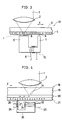
- A magneto-optical recording/reproducing device comprising:light converging means for converging a light beam (1) of substantially constant intensity and irradiating the light beam as a light beam spot (14) on a predetermined area of a magnetic film (4;21),a recording magnetic head (5;22) for recording information by applying a magnetic field (8) on the area on the magnetic film (4;21), the magnetic field reversing in response to the information to be recorded; anda reproducing magnetic head (7;25) for reproducing the information by detecting temporal variation of magnetic flux from the magnetic film (4;21),wherein the recording magnetic head (5;22) and the reproducing magnetic head (7;25) are integrally provided in a single magnetic core (10;28) as an auxiliary magnetic pole and a main magnetic pole respectively, and whereina magnetic core end-face (12;27) of the reproducing magnetic head (7;25) is smaller than the light beam spot (14), and a magnetic core end-face (11;24) of the recording magnetic head (5;22) is larger than the light beam spot.
- A magneto-optical recording/reproducing device according to claim 1, wherein the magneto-optical recording medium is driven in a direction (X) from the reproducing magnetic head (7;25) toward the recording magnetic head (5;22).
- A magneto-optical recording/reproducing device according to claim 2, wherein recording and reproduction are carried out only on and from the magnetic film (4) formed on lands, the lands being located between adjacent segments of the guiding groove of the magneto-optical recording medium.
- A magneto-optical recording/reproducing device according to claim 3, wherein a distance between the magnetic core end-face (24) of the recording magnetic head (22) and the magneto-optical recording medium is greater than a distance between the magnetic core end-face (27) of the reproducing magnetic head (25) and the magneto-optical recording medium.
- A magneto-optical recording/reproducing device according to any of claims 1 to 4, wherein the recording magnetic head and the reproducing magnetic head comprise a single coil (6) wound around the magnetic core (10) to provide both the applied magnetic field (8) for recording information and for detecting fluctuations in the magnetic field (9) for reproduction of the recorded information.
- A magneto-optical recording/reproducing device according to any of claims 1 to 4, wherein first and second coils (23,26) wound around the magnetic core (28) provide the applied magnetic field for recording information and detect fluctuations in the magnetic field for reproduction of the recorded information, respectively.
- A magneto-optical recording system comprising a magneto-optical recording/reproducing device according to claim 1 and a magneto-optical recording medium (18) for use with said device, said magneto-optical recording medium (18) having a soft magnetic material layer (20) formed between a substrate (19) of the magneto-optical recording medium and the magnetic film (21), the soft magnetic material layer (20) being made of soft magnetic material.
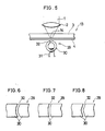
- A magneto-optical recording/reproducing device comprising:light converging means for converging a light beam (1) of substantially constant intensity and irradiating the light beam as a light beam spot (14) on a predetermined area of a magnetic film (4); anda recording and reproducing magnetic head (29) for recording information by applying a magnetic field on the area on the magnetic film (4), the magnetic field reversing in response to information to be recorded, as well as for reproducing the information by detecting temporal variation of magnetic flux from the magnetic film (4),wherein the recording and reproducing magnetic head (29) is ring shaped and has a substantially crescent-shaped gap (32) formed therein, the crescent-shape corresponding to a shape of magnetic domains serving as recording units on the magneto-optical recording medium (13).
Priority Applications (1)
| Application Number | Priority Date | Filing Date | Title |
|---|---|---|---|
| EP97203052A EP0827143B1 (en) | 1990-06-13 | 1991-06-13 | Magneto-optical recording/reproducing device |
Applications Claiming Priority (6)
| Application Number | Priority Date | Filing Date | Title |
|---|---|---|---|
| JP158077/90 | 1990-06-13 | ||
| JP158072/90 | 1990-06-13 | ||
| JP2158077A JPH0775042B2 (en) | 1990-06-13 | 1990-06-13 | Magneto-optical recording / reproducing device |
| JP15807290A JPH0778844B2 (en) | 1990-06-13 | 1990-06-13 | Magneto-optical recording / reproducing device |
| JP162098/90 | 1990-06-20 | ||
| JP2162098A JP2559156B2 (en) | 1990-06-20 | 1990-06-20 | Magneto-optical recording / reproducing device |
Related Child Applications (1)
| Application Number | Title | Priority Date | Filing Date |
|---|---|---|---|
| EP97203052A Division EP0827143B1 (en) | 1990-06-13 | 1991-06-13 | Magneto-optical recording/reproducing device |
Publications (3)
| Publication Number | Publication Date |
|---|---|
| EP0461907A2 EP0461907A2 (en) | 1991-12-18 |
| EP0461907A3 EP0461907A3 (en) | 1994-01-05 |
| EP0461907B1 true EP0461907B1 (en) | 1998-04-22 |
Family
ID=27321288
Family Applications (2)
| Application Number | Title | Priority Date | Filing Date |
|---|---|---|---|
| EP97203052A Expired - Lifetime EP0827143B1 (en) | 1990-06-13 | 1991-06-13 | Magneto-optical recording/reproducing device |
| EP91305374A Expired - Lifetime EP0461907B1 (en) | 1990-06-13 | 1991-06-13 | Magneto-optical recording/reproducing device |
Family Applications Before (1)
| Application Number | Title | Priority Date | Filing Date |
|---|---|---|---|
| EP97203052A Expired - Lifetime EP0827143B1 (en) | 1990-06-13 | 1991-06-13 | Magneto-optical recording/reproducing device |
Country Status (4)
| Country | Link |
|---|---|
| US (2) | US5202862A (en) |
| EP (2) | EP0827143B1 (en) |
| CA (1) | CA2043995C (en) |
| DE (2) | DE69129280T2 (en) |
Families Citing this family (23)
| Publication number | Priority date | Publication date | Assignee | Title |
|---|---|---|---|---|
| US5392263A (en) * | 1990-01-31 | 1995-02-21 | Sony Corporation | Magneto-optical disk system with specified thickness for protective layer on the disk relative to the numerical aperture of the objective lens |
| CA2043995C (en) * | 1990-06-13 | 1997-06-24 | Kenji Ohta | Magneto-optical recording/reproducing device |
| JP3130929B2 (en) * | 1990-08-10 | 2001-01-31 | ミネソタ マイニング アンド マニュファクチャリング カンパニー | Thermomagnetic recording system with high storage density and direct overwrite capability |
| JP2636957B2 (en) * | 1990-08-10 | 1997-08-06 | シャープ株式会社 | Magnetic recording / reproducing device |
| US5910932A (en) * | 1991-09-11 | 1999-06-08 | Sony Corporation | Optical disk and optical disk system with numerical aperture of objective lens related to protective layer thickness of optical disk |
| KR960015209B1 (en) * | 1991-10-21 | 1996-11-01 | 샤프 가부시끼가이샤 | Magneto-optical recording method & magneto-optical memory |
| JPH05197903A (en) * | 1991-10-28 | 1993-08-06 | Canon Inc | Magneto-optical recorder |
| USRE38501E1 (en) | 1992-08-28 | 2004-04-20 | Canon Kabushiki Kaisha | Magnetooptical recording medium and information recording and reproducing methods using the recording medium |
| US5831944A (en) * | 1993-02-26 | 1998-11-03 | Canon Kabushiki Kaisha | Magnetooptical recording medium and method for reproducing information from a magnetooptical recording medium having three layers |
| JPH06302031A (en) * | 1993-02-22 | 1994-10-28 | Sharp Corp | Magneto-optical recording medium and magnetooptical recorder |
| US5563564A (en) * | 1993-04-22 | 1996-10-08 | University Of Houston | Strong high-temperature superconductor trapped field magnets |
| CA2137062A1 (en) * | 1993-12-08 | 1995-06-09 | Takumi Shimamori | Magneto-optical recording and reading-out method |
| WO1995035572A1 (en) * | 1994-06-20 | 1995-12-28 | Neomagic Corporation | Graphics controller integrated circuit without memory interface |
| KR970060108A (en) * | 1996-01-18 | 1997-08-12 | 김광호 | Magneto-optical recording film and magneto-optical disk using the same |
| JP3853512B2 (en) * | 1997-04-21 | 2006-12-06 | 株式会社リコー | Magneto-optic element |
| JP3496113B2 (en) * | 1997-07-02 | 2004-02-09 | 富士通株式会社 | Information recording medium, information recording medium reproducing method, and information recording medium reproducing apparatus |
| US6455174B1 (en) * | 1998-11-05 | 2002-09-24 | Hitachi Maxell, Ltd. | Magnetic recording medium, recording and reproducing head, and magnetic recording and reproducing method |
| US6475611B1 (en) * | 1999-12-14 | 2002-11-05 | Seagate Technology Llc | Si-containing seedlayer design for multilayer media |
| US7688685B1 (en) * | 2000-03-01 | 2010-03-30 | Hitachi, Ltd. | Magneto-optical recording device capable of changing the shapes of heating areas |
| US6873576B1 (en) * | 2000-05-24 | 2005-03-29 | Koninklijke Philips Electronics N.V. | Method of thermally-assisted data recording and a recording apparatus |
| US7554898B2 (en) * | 2002-02-26 | 2009-06-30 | Dphi Acquisitions, Inc. | Dual density disc with associated properties |
| AU2003220878A1 (en) * | 2002-12-24 | 2004-07-22 | Fujitsu Limited | Magnetooptic recording medium and method for producing the same |
| US20050166218A1 (en) * | 2002-12-24 | 2005-07-28 | Fujitsu Limited | Magneto-optical recording medium and method for producing the same |
Family Cites Families (28)
| Publication number | Priority date | Publication date | Assignee | Title |
|---|---|---|---|---|
| JPS5459915A (en) * | 1977-10-20 | 1979-05-15 | Sony Corp | Method and apparatus for reading of magnetic recording signal |
| JPS5634A (en) * | 1979-06-11 | 1981-01-06 | Matsushita Electric Ind Co Ltd | Magnetic recording medium |
| JPS57105838A (en) * | 1980-12-24 | 1982-07-01 | Ricoh Co Ltd | Photo-thermal magnetic recording medium |
| JPS5819753A (en) * | 1981-07-30 | 1983-02-04 | Nec Corp | Vertical magnetic recording medium and reproducing method of vertical magnetizing signal using said recording medium |
| JPS5841451A (en) * | 1981-09-03 | 1983-03-10 | Nec Corp | Vertical magnetic recording medium |
| JPS5851451A (en) * | 1981-09-19 | 1983-03-26 | Mitsubishi Electric Corp | Picture tube |
| JPS5953855A (en) * | 1982-09-21 | 1984-03-28 | Ricoh Co Ltd | Thermomagnetic recording body |
| DE3381422D1 (en) * | 1982-12-23 | 1990-05-10 | Sony Corp | THERMOMAGNETIC OPTICAL RECORDING / PLAYBACK METHOD. |
| JPS6070543A (en) * | 1983-09-28 | 1985-04-22 | Toshiba Corp | Information recording carrier |
| JPS60127548A (en) * | 1983-12-14 | 1985-07-08 | Matsushita Electric Ind Co Ltd | Optical recording and reproducing device |
| JPS6122451A (en) * | 1984-07-09 | 1986-01-31 | Victor Co Of Japan Ltd | Photomagnetic recording medium |
| JPS6171437A (en) * | 1984-09-14 | 1986-04-12 | Fujitsu Ltd | Optomagnetic disc |
| EP0180459B1 (en) * | 1984-10-30 | 1991-12-18 | Brother Kogyo Kabushiki Kaisha | Magneto-optical memory medium and apparatus for writing and reading information on and from the medium |
| JPS61214258A (en) * | 1985-03-20 | 1986-09-24 | Hitachi Ltd | Write and reproducing integrated magnetic head |
| JPS61278060A (en) * | 1985-05-31 | 1986-12-08 | Nec Home Electronics Ltd | Photothermomagnetic recording/reproducing device |
| JPS621148A (en) * | 1985-06-26 | 1987-01-07 | Toshiba Corp | Information recording and reproducing device by photoelectromagnetic effect |
| JPS6243848A (en) * | 1985-08-20 | 1987-02-25 | Seiko Epson Corp | Photomagnetic recording medium |
| US4694358A (en) * | 1985-10-28 | 1987-09-15 | Kerdix, Inc. | Magneto-optic recording structure and method |
| US5051970A (en) * | 1987-05-08 | 1991-09-24 | Nippon Telegraph And Telephone Corporation | Magneto-optic recording system with overwrite capability |
| JPH01107344A (en) * | 1987-10-21 | 1989-04-25 | Hitachi Ltd | Magneto-optical recording medium and production thereof |
| JPH01171137A (en) * | 1987-12-25 | 1989-07-06 | Hitachi Ltd | Magneto-optical recording medium |
| JPH0242664A (en) * | 1988-08-01 | 1990-02-13 | Matsushita Electric Ind Co Ltd | Thermo-magneto-optical recording medium, recording device thereof and thermomagneto-optical recording system using them |
| JP2653523B2 (en) * | 1989-09-08 | 1997-09-17 | シャープ株式会社 | Recording / reproducing method and apparatus for magneto-optical memory element |
| JPH03214447A (en) * | 1990-01-19 | 1991-09-19 | Canon Inc | Magneto-optical recording method |
| CA2043995C (en) * | 1990-06-13 | 1997-06-24 | Kenji Ohta | Magneto-optical recording/reproducing device |
| JP2790716B2 (en) * | 1990-07-27 | 1998-08-27 | キヤノン株式会社 | Magneto-optical recording device |
| JPH117344A (en) * | 1997-06-18 | 1999-01-12 | Nec Shizuoka Ltd | Power saving personal computer |
| JP3651200B2 (en) * | 1997-08-22 | 2005-05-25 | Nok株式会社 | Production method of noble metal fine particle supported photocatalyst thin film |
-
1991
- 1991-06-06 CA CA002043995A patent/CA2043995C/en not_active Expired - Lifetime
- 1991-06-11 US US07/713,742 patent/US5202862A/en not_active Expired - Lifetime
- 1991-06-13 DE DE69129280T patent/DE69129280T2/en not_active Expired - Lifetime
- 1991-06-13 EP EP97203052A patent/EP0827143B1/en not_active Expired - Lifetime
- 1991-06-13 EP EP91305374A patent/EP0461907B1/en not_active Expired - Lifetime
- 1991-06-13 DE DE69133223T patent/DE69133223T2/en not_active Expired - Lifetime
-
1993
- 1993-01-04 US US08/000,271 patent/US5325344A/en not_active Expired - Lifetime
Also Published As
| Publication number | Publication date |
|---|---|
| US5202862A (en) | 1993-04-13 |
| DE69129280D1 (en) | 1998-05-28 |
| DE69129280T2 (en) | 1998-11-05 |
| EP0461907A2 (en) | 1991-12-18 |
| DE69133223T2 (en) | 2004-02-05 |
| DE69133223D1 (en) | 2003-04-24 |
| US5325344A (en) | 1994-06-28 |
| CA2043995A1 (en) | 1991-12-14 |
| EP0461907A3 (en) | 1994-01-05 |
| CA2043995C (en) | 1997-06-24 |
| EP0827143B1 (en) | 2003-03-19 |
| EP0827143A3 (en) | 2000-01-19 |
| EP0827143A2 (en) | 1998-03-04 |
Similar Documents
| Publication | Publication Date | Title |
|---|---|---|
| EP0461907B1 (en) | Magneto-optical recording/reproducing device | |
| US5093822A (en) | High-density magnetic recording and optical reproducing apparatus | |
| JPH0633525Y2 (en) | Magnetic field application mechanism of magneto-optical disk device | |
| US4694358A (en) | Magneto-optic recording structure and method | |
| JP3442296B2 (en) | Magneto-optical head device and recording / reproducing device | |
| KR100241984B1 (en) | Magneto optical recording/reproducing apparatus | |
| JPH0775042B2 (en) | Magneto-optical recording / reproducing device | |
| CA2048583C (en) | Magnetic recording and reproducing apparatus | |
| EP0178423A2 (en) | Magneto-optical recording medium | |
| JP2559156B2 (en) | Magneto-optical recording / reproducing device | |
| JP3104201B2 (en) | Optical recording medium | |
| JP2578411B2 (en) | Magneto-optical information recording device | |
| JP2964517B2 (en) | Magneto-optical pickup device | |
| JP3361336B2 (en) | Information recording and playback system | |
| JPH01251360A (en) | Method for rewriting data of magneto-optical recording and reproducing device | |
| JPH0568763B2 (en) | ||
| JP3022375B2 (en) | Magneto-optical recording medium recording / reproducing device | |
| JP3245190B2 (en) | Information storage device | |
| JP3104202B2 (en) | Optical recording medium | |
| JPS6132244A (en) | Photomagnetic recording device | |
| JP4294843B2 (en) | Magneto-optical disk unit | |
| JPH0448407A (en) | Magneto-optical recording and reproducing device | |
| KR100233420B1 (en) | Optical disk system and optical disk | |
| JPH0660461A (en) | Cylindrical magneto-optical recording medium | |
| JPS60150202A (en) | Reproduction method and its device |
Legal Events
| Date | Code | Title | Description |
|---|---|---|---|
| PUAI | Public reference made under article 153(3) epc to a published international application that has entered the european phase |
Free format text: ORIGINAL CODE: 0009012 |
|
| AK | Designated contracting states |
Kind code of ref document: A2 Designated state(s): DE FR GB IT NL |
|
| PUAL | Search report despatched |
Free format text: ORIGINAL CODE: 0009013 |
|
| AK | Designated contracting states |
Kind code of ref document: A3 Designated state(s): DE FR GB IT NL |
|
| 17P | Request for examination filed |
Effective date: 19940418 |
|
| 17Q | First examination report despatched |
Effective date: 19960531 |
|
| GRAG | Despatch of communication of intention to grant |
Free format text: ORIGINAL CODE: EPIDOS AGRA |
|
| GRAG | Despatch of communication of intention to grant |
Free format text: ORIGINAL CODE: EPIDOS AGRA |
|
| GRAG | Despatch of communication of intention to grant |
Free format text: ORIGINAL CODE: EPIDOS AGRA |
|
| GRAH | Despatch of communication of intention to grant a patent |
Free format text: ORIGINAL CODE: EPIDOS IGRA |
|
| GRAH | Despatch of communication of intention to grant a patent |
Free format text: ORIGINAL CODE: EPIDOS IGRA |
|
| GRAA | (expected) grant |
Free format text: ORIGINAL CODE: 0009210 |
|
| AK | Designated contracting states |
Kind code of ref document: B1 Designated state(s): DE FR GB IT NL |
|
| ITF | It: translation for a ep patent filed |
Owner name: RACHELI & C. S.R.L. |
|
| REF | Corresponds to: |
Ref document number: 69129280 Country of ref document: DE Date of ref document: 19980528 |
|
| ET | Fr: translation filed | ||
| PLBE | No opposition filed within time limit |
Free format text: ORIGINAL CODE: 0009261 |
|
| STAA | Information on the status of an ep patent application or granted ep patent |
Free format text: STATUS: NO OPPOSITION FILED WITHIN TIME LIMIT |
|
| 26N | No opposition filed | ||
| REG | Reference to a national code |
Ref country code: GB Ref legal event code: IF02 |
|
| PGFP | Annual fee paid to national office [announced via postgrant information from national office to epo] |
Ref country code: FR Payment date: 20100709 Year of fee payment: 20 |
|
| PGFP | Annual fee paid to national office [announced via postgrant information from national office to epo] |
Ref country code: IT Payment date: 20100615 Year of fee payment: 20 |
|
| PGFP | Annual fee paid to national office [announced via postgrant information from national office to epo] |
Ref country code: NL Payment date: 20100616 Year of fee payment: 20 |
|
| PGFP | Annual fee paid to national office [announced via postgrant information from national office to epo] |
Ref country code: GB Payment date: 20100609 Year of fee payment: 20 Ref country code: DE Payment date: 20100610 Year of fee payment: 20 |
|
| REG | Reference to a national code |
Ref country code: DE Ref legal event code: R071 Ref document number: 69129280 Country of ref document: DE |
|
| REG | Reference to a national code |
Ref country code: DE Ref legal event code: R071 Ref document number: 69129280 Country of ref document: DE |
|
| REG | Reference to a national code |
Ref country code: NL Ref legal event code: V4 Effective date: 20110613 |
|
| REG | Reference to a national code |
Ref country code: GB Ref legal event code: PE20 Expiry date: 20110612 |
|
| PG25 | Lapsed in a contracting state [announced via postgrant information from national office to epo] |
Ref country code: GB Free format text: LAPSE BECAUSE OF EXPIRATION OF PROTECTION Effective date: 20110612 Ref country code: NL Free format text: LAPSE BECAUSE OF EXPIRATION OF PROTECTION Effective date: 20110613 |
|
| PG25 | Lapsed in a contracting state [announced via postgrant information from national office to epo] |
Ref country code: DE Free format text: LAPSE BECAUSE OF EXPIRATION OF PROTECTION Effective date: 20110614 |