EP0461740A2 - Méthode et dispositif pour tester la dureté d'une pièce d'oeuvre suivant la méthode d'impression - Google Patents
Méthode et dispositif pour tester la dureté d'une pièce d'oeuvre suivant la méthode d'impression Download PDFInfo
- Publication number
- EP0461740A2 EP0461740A2 EP91250152A EP91250152A EP0461740A2 EP 0461740 A2 EP0461740 A2 EP 0461740A2 EP 91250152 A EP91250152 A EP 91250152A EP 91250152 A EP91250152 A EP 91250152A EP 0461740 A2 EP0461740 A2 EP 0461740A2
- Authority
- EP
- European Patent Office
- Prior art keywords
- workpiece
- hardness
- test
- distance sensor
- machining tool
- Prior art date
- Legal status (The legal status is an assumption and is not a legal conclusion. Google has not performed a legal analysis and makes no representation as to the accuracy of the status listed.)
- Withdrawn
Links
- 238000012360 testing method Methods 0.000 title claims abstract description 47
- 238000000034 method Methods 0.000 title claims abstract description 37
- 238000003754 machining Methods 0.000 claims abstract description 39
- 230000035515 penetration Effects 0.000 claims abstract description 4
- 238000005259 measurement Methods 0.000 claims abstract description 3
- 238000012545 processing Methods 0.000 claims description 13
- 238000007542 hardness measurement Methods 0.000 abstract description 5
- 238000004519 manufacturing process Methods 0.000 description 5
- 238000003801 milling Methods 0.000 description 5
- 244000089486 Phragmites australis subsp australis Species 0.000 description 4
- 238000011156 evaluation Methods 0.000 description 4
- 238000010438 heat treatment Methods 0.000 description 4
- 238000005516 engineering process Methods 0.000 description 3
- 238000007373 indentation Methods 0.000 description 3
- 229910000831 Steel Inorganic materials 0.000 description 2
- 238000005261 decarburization Methods 0.000 description 2
- 238000001514 detection method Methods 0.000 description 2
- 238000000227 grinding Methods 0.000 description 2
- 239000000463 material Substances 0.000 description 2
- 239000011159 matrix material Substances 0.000 description 2
- 230000003287 optical effect Effects 0.000 description 2
- 239000010959 steel Substances 0.000 description 2
- 238000010998 test method Methods 0.000 description 2
- 238000004458 analytical method Methods 0.000 description 1
- 238000001816 cooling Methods 0.000 description 1
- 230000006378 damage Effects 0.000 description 1
- 238000011161 development Methods 0.000 description 1
- 230000018109 developmental process Effects 0.000 description 1
- 230000004069 differentiation Effects 0.000 description 1
- 239000005337 ground glass Substances 0.000 description 1
- 230000001939 inductive effect Effects 0.000 description 1
- 230000001105 regulatory effect Effects 0.000 description 1
- 238000005070 sampling Methods 0.000 description 1
- 239000000126 substance Substances 0.000 description 1
- 238000011144 upstream manufacturing Methods 0.000 description 1
Images


Classifications
-
- G—PHYSICS
- G01—MEASURING; TESTING
- G01N—INVESTIGATING OR ANALYSING MATERIALS BY DETERMINING THEIR CHEMICAL OR PHYSICAL PROPERTIES
- G01N3/00—Investigating strength properties of solid materials by application of mechanical stress
- G01N3/40—Investigating hardness or rebound hardness
- G01N3/42—Investigating hardness or rebound hardness by performing impressions under a steady load by indentors, e.g. sphere, pyramid
-
- B—PERFORMING OPERATIONS; TRANSPORTING
- B23—MACHINE TOOLS; METAL-WORKING NOT OTHERWISE PROVIDED FOR
- B23Q—DETAILS, COMPONENTS, OR ACCESSORIES FOR MACHINE TOOLS, e.g. ARRANGEMENTS FOR COPYING OR CONTROLLING; MACHINE TOOLS IN GENERAL CHARACTERISED BY THE CONSTRUCTION OF PARTICULAR DETAILS OR COMPONENTS; COMBINATIONS OR ASSOCIATIONS OF METAL-WORKING MACHINES, NOT DIRECTED TO A PARTICULAR RESULT
- B23Q17/00—Arrangements for observing, indicating or measuring on machine tools
- B23Q17/20—Arrangements for observing, indicating or measuring on machine tools for indicating or measuring workpiece characteristics, e.g. contour, dimension, hardness
-
- G—PHYSICS
- G01—MEASURING; TESTING
- G01N—INVESTIGATING OR ANALYSING MATERIALS BY DETERMINING THEIR CHEMICAL OR PHYSICAL PROPERTIES
- G01N2203/00—Investigating strength properties of solid materials by application of mechanical stress
- G01N2203/0098—Tests specified by its name, e.g. Charpy, Brinnel, Mullen
-
- G—PHYSICS
- G01—MEASURING; TESTING
- G01N—INVESTIGATING OR ANALYSING MATERIALS BY DETERMINING THEIR CHEMICAL OR PHYSICAL PROPERTIES
- G01N2203/00—Investigating strength properties of solid materials by application of mechanical stress
- G01N2203/02—Details not specific for a particular testing method
- G01N2203/06—Indicating or recording means; Sensing means
- G01N2203/0641—Indicating or recording means; Sensing means using optical, X-ray, ultraviolet, infrared or similar detectors
- G01N2203/0647—Image analysis
Definitions
- the invention relates to a method and a device for testing the hardness of a workpiece having a continuously curved outer surface, in particular a tube or rod, according to the penetration method according to the preamble of claims 1 and 5.
- the workpiece manufactured using different methods in particular steel, must have a predetermined minimum strength, which is set either via chemical analysis, the type and size of the forming, with a subsequent heat treatment, if necessary, or via a combination of the methods mentioned becomes.
- the heat treatment can be an integral part of the manufacturing process or a separate step within a sequence of different work steps.
- the correctness of the heat treatment carried out is checked according to the principle of controlled production by means of a hardness test on each piece or according to a sampling plan.
- the hardness value determined can then be assigned to a corresponding strength value. Since the hardness measurement should be carried out as far as possible in the production flow for reasons of the work cycle sequence, a test station with a hardness tester is arranged after the heat treatment unit, depending on the cooling conditions, immediately thereafter or somewhat further away.
- the test station essentially consists of a holding device that fixes the workpiece, a device that carries a machining tool, and a hardness tester.
- the Brinell or Vickers method is used as the method, with the Brinell method usually being preferred.
- the test procedure is such that after the workpiece has been fixed in the roller table, a point on the workpiece surface in the test area is mechanically processed to produce a flat and smooth test surface, this processing being, for example, milling or grinding with a predetermined depth setting.
- the indentation be it a ball or a pyramid, is ideally pressed in with a defined force in the center area of the machined surface.
- the impression of the resulting impression surface is transferred in a known manner to a focusing screen by means of a swivel-in optic. With the aid of known aids, the tester can determine the size of the impression surface by measuring the diameter or the diagonals. This surface is then a measure of the hardness of the tested workpiece with reference values from reference pieces.
- a generic test device suitable for the hardness testing of pipes or rods can be found in US Pat. No. 4,635,471.
- a vertically movable holder with a prism support for the workpiece and a horizontally and vertically displaceable device is arranged, to which a processing tool and a hardness tester are attached.
- the workpiece is fixed on the prism base by means of clamp holders that can be moved on guide rails, and then the displaceable device is positioned on the tube axis.
- a disadvantage of this test device is that a side and / or height offset of the test center resulting from a crooked and / or oval tube cannot be automatically compensated with respect to the support axis and mechanical processing, e.g. B. milling in extreme cases is too deep or not at all and therefore the meaningfulness of the values determined at different material depths is limited.
- JP 70-143739 A discloses an automatically operating hardness tester in which the image contour is recognized by a sensor scanning the test piece and a test location previously determined in its coordinates is found automatically by comparison with a target image stored in a computer.
- the support table for the test piece can be moved in the x and y directions. This procedure is intended to ensure that the same place is always tested for a series of the same test pieces.
- the hardness impression can be placed in an area that does not restrict the use of the workpiece.
- the object of the invention is to provide a method and a device for testing the hardness of a workpiece, with which or in the production flow for workpieces with a continuously curved outer surface, in particular pipes or rods, an automatic hardness test with high informative value is possible.
- a distance sensor before mechanical machining of the workpiece surface detects the contour of the location in the path area of the tool and the horizontal positioning of the hardness tester is based on the determined vertex of the contour.
- the advantage of the method according to the invention can be seen in that the hardness tester can be positioned exactly horizontally by determining the vertex of the continuously curved workpiece surface, and this ensures that the indentation is pressed in in the center region of the machined surface.
- the hardness values determined in this way are very meaningful and the range of fluctuation of the measured values is very small.
- the hardness test is carried out in a known manner in a test laboratory, it is normally no problem to optimally set the conditions required for the hardness measurement and thus to determine meaningful hardness values.
- the hardness test in the flow of a production line is associated with problems, since laboratory conditions are mostly under the harsh operating conditions are not feasible.
- One of the difficulties is to position the machining tool, for example a grinding wheel or a milling cutter, vertically exactly on the vertex of the curved surface in order to obtain a defined machining depth.
- the machining tool for example a grinding wheel or a milling cutter
- the tubes are often slightly curved and the cross-section is not always circular. In these cases, it is not excluded that the center of the machined surface lies next to the machine axis in the case of an egg-shaped pipe cross-section. Since the machining tool is usually set to the nominal outer diameter of the tube or rod and thus to a fixed height position, either no machining takes place or, in another extreme case, at a depth that affects the wall thickness, with the risk that the curved surface of the workpiece will be notched to an impermissibly deep extent.
- the desired machining depth is usually not achieved. If the hardness tester is then set on the machine axis in accordance with the known method, it is possible that the impression of hardness in the case of workpieces made of steel is still in the area of the decarburization zone and thus a too low strength is simulated.
- the proposed method is particularly advantageous for long and heavy pipes, e.g. B. 12 m length, weight> 1t, where it is not possible to bring the pipe axis into line with the machine axis of the test station by means of the clamping force. This means that it is sufficient that the tube or the rod is fixed by the hold-down device, regardless of the position of the tube axis relative to the machine axis.
- deviations of the position of the vertex from the machine axis by ⁇ 50 mm are still in the positioning range of the machining tool and the hardness tester.
- the adjustability of the machining depth also takes the height offset into account.
- the lower edge of the hold-down is detected and the contact with the workpiece surface is chosen as the reference point for the vertical positioning of the processing tool. Based on this point, the machining depth of the tool, for example, is set to a value of - 0.3 mm with a positioning range of -5 mm.
- the choice of the contact of the hold-down with the workpiece surface as a reference point for the vertical positioning of the processing tool is sufficient for workpieces with an almost flat surface and z. B. for rods in which the depth of the hardness impression plays a subordinate role.
- the method becomes more precise if the previously determined vertex of the curved workpiece surface is selected as the reference point. This method ensures that, even with a wavy or uneven surface of the workpiece, regardless of the height of the hold-down device, a machined surface with a precisely defined depth is reproducibly generated.
- the distance sensor scanning the curved contour can be used, this measuring accuracy in 1/100 mm Area should have.
- This second distance sensor works e.g. B. according to the principle of laser technology and has a measuring accuracy of ⁇ 1/100 mm, so that the machining tool can be adjusted to a depth accuracy of ⁇ 1/10 mm.
- the first distance sensor scanning the contour can measure very roughly, since a tolerance value of ⁇ 1 mm is sufficient for the horizontal vertex detection. If two distance sensors are arranged, the depth setting is carried out in such a way that with the height of the hold-down the rough setting for the machining depth takes place and after measuring the distance of the apex by means of the second distance sensor the fine setting for the machining tool.
- a test station which, in a known manner, consists of a workpiece holder, a device holding the machining tool, a hardness tester and an evaluation system which is electrically connected to a scanning device.
- a distance sensor is added to these already known devices, which is fastened together with the machining tool and the hardness tester in the sequence mentioned on a swivel device, the axis of rotation of which is arranged at a defined distance from the machine axis of the test station.
- the devices mentioned can be swiveled into the test area and positioned by means of the swivel device.
- the test procedure now proceeds in such a way that the sensor scanning the contour of the curved workpiece surface is pivoted in a horizontal circular arc over the workpiece region to be tested and, after the workpiece edges have been recognized, the distance from the fixed point of the sensor to the workpiece surface is measured continuously.
- the measured values are a control unit supplied, which calculates the position of the apex center from the parabolic shape of the contour line and uses known mathematical algorithms to determine the pivoting angle of the pivoting device belonging to this point.
- the hardness tester arranged on the swivel device behind the distance sensor and the machining tool which, like the distance sensor and the machining tool, lies on the same swivel diameter, is positioned exactly on the vertex of the contour line in accordance with the swivel angle determined. This ensures that the hardness impression occurs in the middle of the processing surface.
- the aim of the improvement is that, based on the determined vertex, each desired machining depth is constantly regulated with a different height offset of the workpiece.
- the previously known large scatter of the measured hardness values is significantly reduced because the machining depth can be adjusted according to the empirical values about the expected depth of the decarburization in such a way that the indenter is always pressed in the non-decarburized area.
- All types on the market can be used as distance sensors, regardless of whether the scanning is mechanical, inductive, capacitive or optical, the signals being passed on to the control unit in analog or digital form.
- An inductively operating type has proven to be advantageous for the first distance sensor and a type based on laser technology for the second.
- the first-mentioned distance sensor is inexpensive to obtain, since the measurement accuracy placed on it is not very high.
- the second-mentioned distance sensor is considerably more expensive, but has the advantage that this arrangement with two sensors saves on control engineering is compared when using only one sensor.
- the size of the impression area is determined in a known manner by optical scanning of the image projected on a focusing screen.
- a diode matrix camera is used as the scanner, which works on the principle of light-dark differentiation.
- the evaluation method is similar to the already known method and also has the aim of comparing the hardness value that can be calculated via the area determination with a predetermined target value. As already mentioned, this comparison is also used to form a control signal in order to be able to sort the tested workpieces.
- the test station according to the invention can be further improved by, in addition to the devices already listed, a contactless wall thickness measuring device, e.g. a US tester is attached to the swivel device. Since the US tester can be positioned in the same way as the processing tool and the hardness tester, the wall thickness is measured, which corresponds to the thinnest point of the machined surface according to the secant attached. This can prevent pipes from being delivered in which the machined surface for the hardness test falls below the minimum wall thickness at the machined point.
- a contactless wall thickness measuring device e.g. a US tester is attached to the swivel device. Since the US tester can be positioned in the same way as the processing tool and the hardness tester, the wall thickness is measured, which corresponds to the thinnest point of the machined surface according to the secant attached. This can prevent pipes from being delivered in which the machined surface for the hardness test falls below the minimum wall thickness at the machined point.
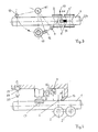
- Figure 1a and 1b show a schematic representation of the position of a pipe 1 to be tested in the ideal state.
- the tube 1 lies on a double-conical roller 2, which is part of a roller table, not shown here.
- the axis 3 of the tube 1 is aligned with the machine axis of the test device 4, so that a machining tool (not shown here) aligned with this machine axis 4 produces a machined surface 5 (here shown in a greatly exaggerated manner) that is orthogonal to the axis 3 of the tube 1 is located and its center is aligned with the apex 6 of the tube 1.
- the outline of the machined surface 5 can be seen in the top view (1b). This representation applies on the assumption that the travel path of the machining tool is perpendicular to the machine axis 4.
- FIGS. 1c and 1d show in a schematic representation the position of a pipe 1 ′ to be tested with heights 7- and lateral offset 8.
- a machined surface 5 ' is generated, which is completely unusable for the hardness test, since it would lead to the destruction of the tube 1'.
- the test site 6 'for the hardness impression would no longer lie in the center of the machined surface 5', but on the edge.
- the contour of the curved pipe surface is detected according to the invention by means of a sensor 9 (FIG.
- the determined vertex 6 ′′ which is at the same time a test site for the positioning of the hardness tester 18 (FIG. 3), is a prerequisite for the generation of a usable machined surface 5 ′′ for a pipe 1 ′ lying vertically and laterally offset. The hardness impression is then in the middle of the machined surface 5 ''.
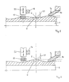
- the measuring method for determining the vertex is shown schematically in FIG. 2.
- a pipe 1 to be tested is mounted on a roll 2, as in FIG. 1a.
- the received signal of the sensor 9 is plotted on the ordinate 10 and the travel path alpha of the sensor 9 is plotted on the abscissa 11.
- the position of the sensor 9 relative to the tube 1 is shown in three partial positions between the two partial images.
- the resulting parabolic contour profile 12 of the pipe curvature is shown in the upper part of the picture, the trigger level 13 being within a certain range Bandwidth can be set arbitrarily.
- the trigger points for determining the vertex 6 are identified with S1 and S2 in the lower partial image.
- Figure 3 shows a top view and Figure 4 in a front view schematically the test station according to the invention.
- the pipe 1 to be tested is pressed and clamped onto the rollers 2, 2 'by a hold-down device 14 with the force F N.
- the ideal state is assumed that the pipe axis 3 is aligned with the machine axis 4 of the test station.
- the sensor 9 for determining the vertex 6 can be pivoted on an axis of rotation 15 and a sensor 16 for adjusting the machining depth (see FIGS. 5 and 6) and the machining tool 17 and the indenter 18 of the hardness tester (not shown here) are connected downstream arranged.
- Arrow 19 indicates the travel distance alpha during the swiveling movement.
- the indenter 18 is pressed into the tube 1 with a predetermined force F D on the center of the previously machined surface.
- the optional use of a Brinell ball 19 or a Vickers pyramid 20 is sketched out here.
- FIGS. 5 and 6 the setting of the machining depth 21 for tubes 1 with a strongly uneven surface is shown schematically using two examples.
- a milling cutter is used here as the machining tool 17 for producing the machined impression surface 5, since a milled surface is completely flat and does not tend to be spherical like a ground surface.
- the sensor 16 upstream of the machining tool 17 measures the pipe height position in the previously determined vertex 6, which corresponds to the zero position of the machining tool 17. From then on, the specified area is machined with the specified setpoint for the milling depth 21.
- the height adjustability of the machining tool 17 is indicated by an arrow 22.
- FIG. 7 shows the flow chart of the method according to the invention.
- the pipes can be automatically run through in various troughs, so that the material flow for the good pipes remains undisturbed.
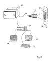
- FIG. 8 shows the measuring device for recording the image of the indentation surface 23 on the focusing screen 24 in order to automate the determination of the hardness value.
- a diode matrix camera 25 here only the optics are reproduced, scans the image of the impression surface 23 on the focusing screen 24.
- the camera 25 is connected via a cable 26 to an evaluation device 27, which in turn is linked to a computer 28.
- the image of the impression surface 23 can additionally be displayed on a control monitor 29, while the determined surface data including the test parameters appear on a data monitor 30.
- the keyboard 31 serves as a control panel for the start and end of the test sequence and can also be used to make various queries regarding the area determination.
Applications Claiming Priority (4)
| Application Number | Priority Date | Filing Date | Title |
|---|---|---|---|
| DE4019120 | 1990-06-12 | ||
| DE4019120 | 1990-06-12 | ||
| DE4119564 | 1991-06-11 | ||
| DE4119564A DE4119564C2 (de) | 1990-06-12 | 1991-06-11 | Verfahren und Vorrichtung zur Prüfung der Härte eines Werkstückes nach dem Eindringverfahren |
Publications (2)
| Publication Number | Publication Date |
|---|---|
| EP0461740A2 true EP0461740A2 (fr) | 1991-12-18 |
| EP0461740A3 EP0461740A3 (en) | 1992-04-08 |
Family
ID=25894161
Family Applications (1)
| Application Number | Title | Priority Date | Filing Date |
|---|---|---|---|
| EP19910250152 Withdrawn EP0461740A3 (en) | 1990-06-12 | 1991-06-11 | Method and apparatus for testing the hardness of a workpiece using the impression method |
Country Status (3)
| Country | Link |
|---|---|
| US (1) | US5195364A (fr) |
| EP (1) | EP0461740A3 (fr) |
| DE (1) | DE4119564C2 (fr) |
Cited By (1)
| Publication number | Priority date | Publication date | Assignee | Title |
|---|---|---|---|---|
| WO2015039875A1 (fr) * | 2013-09-23 | 2015-03-26 | Man Diesel & Turbo Se | Machine-outil munie d'un dispositif de mesure de dureté |
Families Citing this family (11)
| Publication number | Priority date | Publication date | Assignee | Title |
|---|---|---|---|---|
| US6134954A (en) * | 1996-04-15 | 2000-10-24 | Massachusetts Institute Of Technology | Depth sensing indentation and methodology for mechanical property measurements |
| US5999887A (en) * | 1997-02-26 | 1999-12-07 | Massachusetts Institute Of Technology | Method and apparatus for determination of mechanical properties of functionally-graded materials |
| US6641893B1 (en) | 1997-03-14 | 2003-11-04 | Massachusetts Institute Of Technology | Functionally-graded materials and the engineering of tribological resistance at surfaces |
| US6067846A (en) * | 1997-10-27 | 2000-05-30 | Hill; Jack O. | Apparatus and method for testing the hardness of a pipe |
| JP2000180330A (ja) * | 1998-12-14 | 2000-06-30 | Edison Haado Kk | 硬度計 |
| US7412900B2 (en) * | 2005-09-30 | 2008-08-19 | Rockwell Automation Technologies, Inc. | Sensor mounting structure with adjustable swivel ball and panel mounting mechanism |
| US7546780B2 (en) * | 2005-09-30 | 2009-06-16 | Rockwell Automation Technologies, Inc. | Sensor mounting structure allowing for adjustment of sensor position |
| US7415891B2 (en) * | 2005-09-30 | 2008-08-26 | Rockwell Automation Technologies, Inc. | Sensor mounting structure with snapping feature |
| US7527437B2 (en) * | 2005-09-30 | 2009-05-05 | Rockwell Automation Technologies, Inc. | Sensor mounting structure with light pipe |
| CN109062013B (zh) * | 2018-09-06 | 2023-06-06 | 重庆科技学院 | 一种光刻机小工件卡具 |
| CN114653783A (zh) * | 2020-12-22 | 2022-06-24 | 上海飞机制造有限公司 | 一种冲压成形方法 |
Citations (2)
| Publication number | Priority date | Publication date | Assignee | Title |
|---|---|---|---|---|
| US4635471A (en) * | 1986-01-16 | 1987-01-13 | Energy Development Corporation | Hardness testing device for pipes |
| US4719793A (en) * | 1986-12-08 | 1988-01-19 | Amsted Industries Incorporated | Hardness testing apparatus |
Family Cites Families (4)
| Publication number | Priority date | Publication date | Assignee | Title |
|---|---|---|---|---|
| US3295363A (en) * | 1962-11-16 | 1967-01-03 | Loire Atel Forges | Hardness-testing system |
| US3822946A (en) * | 1972-12-07 | 1974-07-09 | Schiller Industries Inc | Dimensional measuring apparatus using optical scan especially for hardness testing |
| IT8121486V0 (it) * | 1981-04-14 | 1981-04-14 | Bavelloni Z Spa | Dispositivo per il posizionamento e l'azionamento di utensili rotanti, in una macchina per la lavorazione di lastre di vetro marmi e simili. |
| US4852397A (en) * | 1988-01-15 | 1989-08-01 | Haggag Fahmy M | Field indentation microprobe for structural integrity evaluation |
-
1991
- 1991-06-11 EP EP19910250152 patent/EP0461740A3/de not_active Withdrawn
- 1991-06-11 DE DE4119564A patent/DE4119564C2/de not_active Expired - Fee Related
- 1991-06-12 US US07/713,872 patent/US5195364A/en not_active Expired - Fee Related
Patent Citations (2)
| Publication number | Priority date | Publication date | Assignee | Title |
|---|---|---|---|---|
| US4635471A (en) * | 1986-01-16 | 1987-01-13 | Energy Development Corporation | Hardness testing device for pipes |
| US4719793A (en) * | 1986-12-08 | 1988-01-19 | Amsted Industries Incorporated | Hardness testing apparatus |
Cited By (2)
| Publication number | Priority date | Publication date | Assignee | Title |
|---|---|---|---|---|
| WO2015039875A1 (fr) * | 2013-09-23 | 2015-03-26 | Man Diesel & Turbo Se | Machine-outil munie d'un dispositif de mesure de dureté |
| US10875139B2 (en) | 2013-09-23 | 2020-12-29 | Man Energy Solutions Se | Machine tool comprising a hardness testing device |
Also Published As
| Publication number | Publication date |
|---|---|
| EP0461740A3 (en) | 1992-04-08 |
| US5195364A (en) | 1993-03-23 |
| DE4119564C2 (de) | 1993-12-02 |
| DE4119564A1 (de) | 1991-12-19 |
Similar Documents
| Publication | Publication Date | Title |
|---|---|---|
| DE102012104008B3 (de) | Vorrichtung und Verfahren zum Messen von Form-, Lage- und Dimensionsmerkmalen an Maschinenelementen | |
| EP2252855B1 (fr) | Procédé et dispositif de détermination de la position et de l'orientation d'un échantillon | |
| DE4119564C2 (de) | Verfahren und Vorrichtung zur Prüfung der Härte eines Werkstückes nach dem Eindringverfahren | |
| WO2014114737A2 (fr) | Procédé et dispositif de détermination de la géométrie de structures au moyen de la tomographie assistée par ordinateur | |
| EP1904260A1 (fr) | Procede et dispositif pour determiner un mouvement relatif lateral entre une tete d'usinage et une piece | |
| WO2020094709A2 (fr) | Procédé et produit-programme d'ordinateur pour ajuster un rayon de mesure oct | |
| DE102012008433A1 (de) | Vorrichtung und Verfahren zur 3D-Erfassung eines Rohres | |
| EP3225322B1 (fr) | Procédé et machine à plier destinés à la fabrication d'un élément à plier courbé multidimensionnel | |
| EP3710777B1 (fr) | Dispositif pour la mesure optique du profil de filetage extérieur de tubes | |
| DE102006011796A1 (de) | Werkzeugmess- und/oder Einstellvorrichtung mit einer Sensoreinheit | |
| EP3465079B1 (fr) | Dispositif de mesure d'un filetage | |
| EP2590761A2 (fr) | Train de laminage ainsi que dispositif et procédé de détermination des calibres de laminage ou de guidage des cages de laminoir ou de guidage dans un train de laminage à plusieurs cages | |
| DE102017010055A1 (de) | Laserstrahlschweißen von geometrischen Figuren mit OCT-Nahtführung | |
| EP0403908B1 (fr) | Procédé et dispositif pour mesurer les contours d'un objet | |
| DE102017125033A1 (de) | Verfahren und Industrieroboter zur Prüfung von Schweißverbindungen, insbesondere von Schweißpunkten | |
| EP1238746A2 (fr) | Méthode et appareil de découpe et soudage laser à commande robotique | |
| WO2016207303A1 (fr) | Élément adapteur pour le montage d'un dispositif rotatif dans la chambre de mesure d'un appareil de mesure de coordonnées | |
| DE19604354A1 (de) | Verfahren zur koordinatenmäßigen Vermessung von Werkstücken auf Bearbeitungsmaschinen | |
| EP0771406B1 (fr) | Dispositif et procede de mesure et de calcul de parametres geometriques d'un corps | |
| EP2745945A1 (fr) | Procédé et dispositif destinés à la mesure géométrique sans contact d'un objet de mesure | |
| DE19725159C1 (de) | Meßanordnung zum Erfassen und Vermessen von Brillenbauteilen | |
| DE10319711B4 (de) | Verfahren zur hochgenauen dimensionalen Messung an Messobjekten | |
| EP1514638A2 (fr) | Procédé et dispositif pour usiner une pièce serrée d'un moyen de serrage | |
| DE19827364B4 (de) | Verfahren zum Messen kegeliger Gewinde | |
| DE102022104804A1 (de) | Verfahren und Vorrichtung zum Bearbeiten von Werkstücken mit einer automatischen Lageerfassung der Werkstücke |
Legal Events
| Date | Code | Title | Description |
|---|---|---|---|
| PUAI | Public reference made under article 153(3) epc to a published international application that has entered the european phase |
Free format text: ORIGINAL CODE: 0009012 |
|
| AK | Designated contracting states |
Kind code of ref document: A2 Designated state(s): AT DE ES FR GB IT |
|
| PUAL | Search report despatched |
Free format text: ORIGINAL CODE: 0009013 |
|
| AK | Designated contracting states |
Kind code of ref document: A3 Designated state(s): AT DE ES FR GB IT |
|
| 17P | Request for examination filed |
Effective date: 19920312 |
|
| 17Q | First examination report despatched |
Effective date: 19940525 |
|
| STAA | Information on the status of an ep patent application or granted ep patent |
Free format text: STATUS: THE APPLICATION IS DEEMED TO BE WITHDRAWN |
|
| 18D | Application deemed to be withdrawn |
Effective date: 19950323 |