EP0461679A2 - Bar like article supplying apparatus in hopper - Google Patents
Bar like article supplying apparatus in hopper Download PDFInfo
- Publication number
- EP0461679A2 EP0461679A2 EP91114133A EP91114133A EP0461679A2 EP 0461679 A2 EP0461679 A2 EP 0461679A2 EP 91114133 A EP91114133 A EP 91114133A EP 91114133 A EP91114133 A EP 91114133A EP 0461679 A2 EP0461679 A2 EP 0461679A2
- Authority
- EP
- European Patent Office
- Prior art keywords
- bar
- articles
- hopper
- box
- lids
- Prior art date
- Legal status (The legal status is an assumption and is not a legal conclusion. Google has not performed a legal analysis and makes no representation as to the accuracy of the status listed.)
- Granted
Links
Images


Classifications
-
- A—HUMAN NECESSITIES
- A24—TOBACCO; CIGARS; CIGARETTES; SIMULATED SMOKING DEVICES; SMOKERS' REQUISITES
- A24C—MACHINES FOR MAKING CIGARS OR CIGARETTES
- A24C5/00—Making cigarettes; Making tipping materials for, or attaching filters or mouthpieces to, cigars or cigarettes
- A24C5/35—Adaptations of conveying apparatus for transporting cigarettes from making machine to packaging machine
- A24C5/352—Adaptations of conveying apparatus for transporting cigarettes from making machine to packaging machine using containers, i.e. boats
- A24C5/356—Emptying the boats into the hopper of the packaging machine
Definitions
- This invention relates to an apparatus for supplying bar-like articles, more specifically bar-like articles such as cigarettes, filter plugs, etc, to a hopper.
- a plurality of plug supplying apparatus are provided below a hopper in which filter plugs are arranged in one direction and received in an accumulated fashion, and each of the plug supplying apparatus is connected to the cigarette producing machines.
- Filter plugs should desireably be received within the hopper so that the upper surfaces of the mass of plugs should be flat.
- the rate of consumption of the filter of the plugs by respective supplying apparatus is different or varied in dependence upon the producing speed or operating rate of respective cigarette producing machines, and therefore, the rate of consumption of filter plugs is not even throughout the mass so that the upper surface thereof becomes rugged and uneven.
- Filter plugs are normally supplied in quantity to the hopper in a generally rectangular parallelopiped box and they are arranged in parallel mass; the filter plugs are supplied into the hopper from the box by means of a supplying device constructed as described hereinafter.
- the supplying device is composed of a mounting frame that is reversible between up and down positions and on which said box is mounted, and there is a bottom lid that may be opened and closed to close the otherwise open bottom surface of the box.
- the box is mounted on the mounting frame when in the down position so that the open bottom surface of the box is directed upward, the open bottom surface of the box being closed by a bottom lid of the supplying device.
- the box is reversed to move the said bottom lid adjacent the upper surface of the hopper, and then the bottom lid is pulled out and/or opened whereby the filter plugs fall from the box into the hopper.
- the aforesaid bottom lid is composed of a single plate, which is pulled out horizontally and therefore the stroke thereof becomes extremely great and the entire apparatus becomes large-scaled.
- the upper surface of the mass of filter plugs within the hopper is rugged and uneven due to the difference in consumption speeds as explained herein, some of the filter plugs falling from the box wall rolled slantwise from a raised portion of said surface toward a depressed portion which can cause a loss of attitude, thus posing inconveniences such that the filter plugs disturbed in attitude tend to foul the supply of the bar-like articles causing a loss of efficiency.
- the present invention seeks to overcome the above-described drawbacks as noted above, and an object of the invention is to provide a supplying apparatus which reduces the loss of attitude of bar-like articles to a minimum.
- a supplying apparatus for supplying bar-like articles to a hopper, comprising means for receiving a box containing said bar-like articles so that the box with its bottom open can be located above the hopper, a bottom lid closing said open bottom of the box preventing said bar-like articles from falling from the box into the hopper, characterised in that said bottom end is divided into a plurality of bottom lid sections each movably mounted and openable to allow the bar-like articles in said box above each lid to fall through the space created by the opening of each of said sections.
- apparatus for supplying bar-like articles to a hopper wherein, a box filled with bar-like parallel arranged articles is arranged on the hopper in a condition that the box is closed by a bottom lid preventing the articles from falling into the hopper, said bottom lid being divided into a plurality of small bottom lids, said small bottom lids being provided so that they may be rotated to create openings through which the articles can fall.
- supplying apparatus for supplying bar-like articles to a hopper wherein a box filled with bar-like parallel arranged articles is arranged on the hopper in a condition that the box is closed by a bottom lid, said bottom lid being divided into a plurality of small bottom lids, said small bottom lids being provided so that they may be rotated until an upper end of each of the small bottom lids fronts into said box, each of said small bottom lids being pivotally moved.
- the plurality of small bottom lids obtained by division of the bottom lid are respectively rotated about axes parallel to the bar-like articles to supply the bar-like articles through the openings left by rotating the small bottom lids. Therefore, the moving stroke to pivot the small bottom lids becomes extremely small as compared with prior art in which the bottom lid in the form of a single plate is moved in a horizontal direction of bar-like articles and is pulled out.
- the invention enables a miniaturization of the entire apparatus, and as bar-like articles will fall directly onto the depressed portion of the upper surface of the mass of bar-like articles within the hopper, whereby the upper surface of mass of bar-like articles within the hopper is maintained approximatley flat, with the result that bar-like articles are not rolled slantwise from the raised portion toward the depressed portion of said surface and disturbance of attitude and the bar-like articles in avoided.
- a preferred feature of the invention provides an arrangement wherein each of the small bottom lids is oscillated when in the open position to distribute the bar-like articles within the box evenly, and therefore, bar-like articles may be supplied very quickly and orderly from the box toward the hopper so that there is enough time to insert the succeeding box and no delay in work occurs.
- a hopper is indicated at 1, a supplying device at 2, a controller at 3 and a supplying device at 10.
- the hopper 1 comprises, as shown in Fig. 3, two plates 1a disposed parallel to each other and spaced apart approximately equal to the length of filter plugs B in a lateral direction, and bottom plates 1b defining a V shape disposed therebelow, a plurality of supplying devices 2 being juxtaposed below the bottom plates 1b.
- Partition plates serve to define cavities leading to the respective supplying devices 2.
- Each bottom plate 1b consists of two small bottom plates which are superimposed, and where only two supplying apparatuses 2 are used, the small bottom plates may be extended to block off the apparatuses 2 as shown by the broken lines.
- Each supplying apparatus 2 consists, as shown in section in Fig. 3, of two cylindrical bodies 2a, in the form of gears, which are movable up and down.
- the filter plugs B are engaged one by one in the tooth-groves 2b of the cylindrical bodies 2 and eventually the filter plugs are moved out one by one from a hole 2c provided at the bottom of the supplying apparatus 2.
- Each supplying apparatus is connected to a respective cigarette producing machine not shown.
- Pivotal arms 11 are respectively provided on the opposite sides of the hopper 1, as shown in Figs 1 and 2, and said arms can be pivoted up and down, and a supplying apparatus 10 extends over the front end of the pivotal arms 11.
- the pivotal arms 11 are operated such that when the pivotal arms 11 are in an upper portion, the supplying apparatus 10 assumes a position above the hopper 1 as shown in full lines in Figs. 1 and 2, whereas when the pivotal arms are in a lower position as shown in dotted lines in Fig. 2 the supplying apparatus 10 assumes a position frontwardly of the hopper 1.
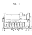
- the supplying apparatus 10 principally comprises a bottom plate 12, a bottom lid A, a mounting plate 13, a mounting frame 14, an air cylinder 15 and an anchor plate 16, as shown in Figs. 1, 4 and 5.
- the bottom plate 12 is designed so that as shown in Figs. 4 and 5, an elongated plate 12b in the form of a gate in section extends over side plates 12a which are pivotally mounted on the pivotal arms 11.
- Rotational shafts 17 are juxtaposed at predetermined intervals on the elongated plate 12b and on one projecting end of each shaft 17 is a small bottom lid, all of the small bottom lids thereby constituting a bottom lid A.
- Operating arms 18 are respectively connected to the rotational shafts 17, respectively as shown in Figs. 5 and 6, and engaging rollers 19 are provided respectively on the ends of the operating arms 18.
- the engaging plate 16 comprises engaging pieces 16b which are parallel to each other and are spaced at predetermined intervals on a horizontal plate 16a.
- Plate 16a is parallel to and below the bottom plate 12, the horizontal plate 16a having one end connected to an air cylinder 15 provided on the end of the bottom plate 12.
- the air cylinder 15 is designed so that when it is at one end of its stroke, corresponding to an OFF position, it is extended and each engaging piece 16b urges each engaging roller 19 to keep arm 18 in a position in which each small bottom lid closes the space between its neighbours (Fig. 5) and when the piston at the other end of its stroke, the ON position, it is withdrawn to dissengage each engaging piece 16b from each engaging roller 19 and each small bottom lid moves to an open position by its own weight (Fig. 6).
- a mounting plate 13 as shown in Figs. 1 and 2 stands upright on the bottom plate 12, and a mounting frame 14 extends over the mounting plate 13.
- the mounting frame 14 is composed of a front plate portion 14a, a side plate portion 14b and an upper plate portion 14c so that a box C filled with filter plugs can be placed on the mounting frame 14 as indicated by the broken lines in Fig. 2 and maintained so as to be reversed into the position as indicated by the solid lines.
- the apparatus described operates as follows: First the consumption of the mass of filter plugs B within the hopper 1 to such an extent that the hopper needs to be replenished is detected by means of a detector or visually. Subsequently, the box C filled with filter plugs is fitted on mounting frame 14 as indicated by the broken lines in Fig. 2 and is inverted as indicated by the solid lines. At that time, the air cylinder 15 is in the OFF condition as shown in Fig. 5, and the bottom lid A is closed preventing the filter plugs from falling from the bottom of box C which is otherwise open. Then, the level of the box C is adjusted to the upper surface of the filter plugs B within the hopper 1, and the air cylinder 15 is turned ON.
- the apparatus is designed so that each of the small bottom lids a is opened by its own weight, it is to be noted that a torsional coil spring may be provided on each of the small bottom lids a, so that the lid may be urged by spring pressure in the direction of opening.
- U-shaped engaging pieces 16c are provided in place of the inverted L-shaped engaging pieces 16b in the first embodiment, and each of the small bottom lids a is in the form of a projection so that when the ends are opened as shown in Fig. 8, the upper ends a' front or project into the box C.
- the controller 3 periodically turns on and off the air cylinder 15 during the time the small bottom lids a are opened and the lids a may be pivotally moved back and forth continuously or from time to time with stroke of S in Fig. 8.
- Other mechanical structures of this embodiment are substantially the same as those of the first embodiment, and explanation thereof will be omitted.
- the air cylinder 15 is periodically turned on and off by the controller 3 and the small bottom lids a are pivotally moved with the stroke S.
- the filter plugs B are preferentially supplied to the depressed portion of the surface of the mass of plugs in the hopper.
- the portion where the filter plugs B are preferentially supplied within the box C corresponds to the said depressed portion, but the small bottom lids a are pivotally moved whereby the filter plugs B within the box C are forcibly distributed in the box C and the upper surface of the filter plugs B in the hopper becomes flat.
Abstract
Description
- This invention relates to an apparatus for supplying bar-like articles, more specifically bar-like articles such as cigarettes, filter plugs, etc, to a hopper.
- In the past, for example, in the case where filter plugs are supplied to a plurality of cigarette producing machines, a plurality of plug supplying apparatus are provided below a hopper in which filter plugs are arranged in one direction and received in an accumulated fashion, and each of the plug supplying apparatus is connected to the cigarette producing machines.
- Filter plugs should desireably be received within the hopper so that the upper surfaces of the mass of plugs should be flat. However, the rate of consumption of the filter of the plugs by respective supplying apparatus is different or varied in dependence upon the producing speed or operating rate of respective cigarette producing machines, and therefore, the rate of consumption of filter plugs is not even throughout the mass so that the upper surface thereof becomes rugged and uneven.
- Filter plugs are normally supplied in quantity to the hopper in a generally rectangular parallelopiped box and they are arranged in parallel mass; the filter plugs are supplied into the hopper from the box by means of a supplying device constructed as described hereinafter.
- The supplying device is composed of a mounting frame that is reversible between up and down positions and on which said box is mounted, and there is a bottom lid that may be opened and closed to close the otherwise open bottom surface of the box. First, the box is mounted on the mounting frame when in the down position so that the open bottom surface of the box is directed upward, the open bottom surface of the box being closed by a bottom lid of the supplying device. Next the box is reversed to move the said bottom lid adjacent the upper surface of the hopper, and then the bottom lid is pulled out and/or opened whereby the filter plugs fall from the box into the hopper.
- The aforesaid bottom lid is composed of a single plate, which is pulled out horizontally and therefore the stroke thereof becomes extremely great and the entire apparatus becomes large-scaled.
- Invariably, when the filter plugs are so supplied, the upper surface of the mass of filter plugs within the hopper is rugged and uneven due to the difference in consumption speeds as explained herein, some of the filter plugs falling from the box wall rolled slantwise from a raised portion of said surface toward a depressed portion which can cause a loss of attitude, thus posing inconveniences such that the filter plugs disturbed in attitude tend to foul the supply of the bar-like articles causing a loss of efficiency.
- The present invention seeks to overcome the above-described drawbacks as noted above, and an object of the invention is to provide a supplying apparatus which reduces the loss of attitude of bar-like articles to a minimum.
- According to a first aspect of the present invention there is provided a supplying apparatus for supplying bar-like articles to a hopper, comprising means for receiving a box containing said bar-like articles so that the box with its bottom open can be located above the hopper, a bottom lid closing said open bottom of the box preventing said bar-like articles from falling from the box into the hopper, characterised in that said bottom end is divided into a plurality of bottom lid sections each movably mounted and openable to allow the bar-like articles in said box above each lid to fall through the space created by the opening of each of said sections.
- According to a second aspect of the invention there is provided apparatus for supplying bar-like articles to a hopper wherein, a box filled with bar-like parallel arranged articles is arranged on the hopper in a condition that the box is closed by a bottom lid preventing the articles from falling into the hopper, said bottom lid being divided into a plurality of small bottom lids, said small bottom lids being provided so that they may be rotated to create openings through which the articles can fall.
- According to a third aspect of the present invention, there is provided supplying apparatus for supplying bar-like articles to a hopper wherein a box filled with bar-like parallel arranged articles is arranged on the hopper in a condition that the box is closed by a bottom lid, said bottom lid being divided into a plurality of small bottom lids, said small bottom lids being provided so that they may be rotated until an upper end of each of the small bottom lids fronts into said box, each of said small bottom lids being pivotally moved.
- According to the preferred supplying apparatus of the present invention, the plurality of small bottom lids obtained by division of the bottom lid are respectively rotated about axes parallel to the bar-like articles to supply the bar-like articles through the openings left by rotating the small bottom lids. Therefore, the moving stroke to pivot the small bottom lids becomes extremely small as compared with prior art in which the bottom lid in the form of a single plate is moved in a horizontal direction of bar-like articles and is pulled out. The invention enables a miniaturization of the entire apparatus, and as bar-like articles will fall directly onto the depressed portion of the upper surface of the mass of bar-like articles within the hopper, whereby the upper surface of mass of bar-like articles within the hopper is maintained approximatley flat, with the result that bar-like articles are not rolled slantwise from the raised portion toward the depressed portion of said surface and disturbance of attitude and the bar-like articles in avoided.
- Furthermore, in addition to the aforementioned effect, a preferred feature of the invention provides an arrangement wherein each of the small bottom lids is oscillated when in the open position to distribute the bar-like articles within the box evenly, and therefore, bar-like articles may be supplied very quickly and orderly from the box toward the hopper so that there is enough time to insert the succeeding box and no delay in work occurs.
- Embodiments of the invention will now be described, by way of example, with reference to the accompanying drawings, wherein:-
- Fig. 1 is a front view of a bar-like article supplying apparatus according to one embodiment of the present invention;
- Fig. 2 is a side view of the apparatus of Fig.1;
- Fig. 3 is a longitudinal sectional view in an enlarged scale of the apparatus of Fig. 1;
- Fig. 4 is a cross-sectional plan view of the apparatus of Fig. 1;
- Fig. 5 is a front view showing a bottom lid in an enlarged scale;
- Fig. 6 is a view of the bottom end in an opened condition;
- Fig. 7 is a front view showing a bottom lid of the second embodiment of the invention; and
- Fig. 8 is a view showing a pivotal state of Fig. 7.
- A first embodiment of a first invention will now be described with reference to Figs. 1 to 6. In Fig. 1, a hopper is indicated at 1, a supplying device at 2, a controller at 3 and a supplying device at 10.
- The hopper 1 comprises, as shown in Fig. 3, two plates 1a disposed parallel to each other and spaced apart approximately equal to the length of filter plugs B in a lateral direction, and bottom plates 1b defining a V shape disposed therebelow, a plurality of supplying
devices 2 being juxtaposed below the bottom plates 1b. Partition plates serve to define cavities leading to the respective supplyingdevices 2. - Each bottom plate 1b consists of two small bottom plates which are superimposed, and where only two supplying
apparatuses 2 are used, the small bottom plates may be extended to block off theapparatuses 2 as shown by the broken lines. - Each supplying
apparatus 2 consists, as shown in section in Fig. 3, of twocylindrical bodies 2a, in the form of gears, which are movable up and down. The filter plugs B are engaged one by one in the tooth-groves 2b of thecylindrical bodies 2 and eventually the filter plugs are moved out one by one from ahole 2c provided at the bottom of the supplyingapparatus 2. Each supplying apparatus is connected to a respective cigarette producing machine not shown. - Pivotal arms 11 are respectively provided on the opposite sides of the hopper 1, as shown in Figs 1 and 2, and said arms can be pivoted up and down, and a supplying
apparatus 10 extends over the front end of the pivotal arms 11. The pivotal arms 11 are operated such that when the pivotal arms 11 are in an upper portion, the supplyingapparatus 10 assumes a position above the hopper 1 as shown in full lines in Figs. 1 and 2, whereas when the pivotal arms are in a lower position as shown in dotted lines in Fig. 2 the supplyingapparatus 10 assumes a position frontwardly of the hopper 1. - The supplying
apparatus 10 principally comprises abottom plate 12, a bottom lid A, amounting plate 13, amounting frame 14, anair cylinder 15 and ananchor plate 16, as shown in Figs. 1, 4 and 5. - The
bottom plate 12 is designed so that as shown in Figs. 4 and 5, anelongated plate 12b in the form of a gate in section extends overside plates 12a which are pivotally mounted on the pivotal arms 11.Rotational shafts 17 are juxtaposed at predetermined intervals on theelongated plate 12b and on one projecting end of eachshaft 17 is a small bottom lid, all of the small bottom lids thereby constituting a bottom lid A. - Operating
arms 18 are respectively connected to therotational shafts 17, respectively as shown in Figs. 5 and 6, andengaging rollers 19 are provided respectively on the ends of the operatingarms 18. - The
engaging plate 16 comprisesengaging pieces 16b which are parallel to each other and are spaced at predetermined intervals on ahorizontal plate 16a.Plate 16a is parallel to and below thebottom plate 12, thehorizontal plate 16a having one end connected to anair cylinder 15 provided on the end of thebottom plate 12. - The
air cylinder 15 is designed so that when it is at one end of its stroke, corresponding to an OFF position, it is extended and eachengaging piece 16b urges eachengaging roller 19 to keeparm 18 in a position in which each small bottom lid closes the space between its neighbours (Fig. 5) and when the piston at the other end of its stroke, the ON position, it is withdrawn to dissengage eachengaging piece 16b from eachengaging roller 19 and each small bottom lid moves to an open position by its own weight (Fig. 6). - A
mounting plate 13 as shown in Figs. 1 and 2 stands upright on thebottom plate 12, and amounting frame 14 extends over themounting plate 13. - The
mounting frame 14 is composed of a front plate portion 14a, aside plate portion 14b and anupper plate portion 14c so that a box C filled with filter plugs can be placed on themounting frame 14 as indicated by the broken lines in Fig. 2 and maintained so as to be reversed into the position as indicated by the solid lines. - The apparatus described operates as follows:
First the consumption of the mass of filter plugs B within the hopper 1 to such an extent that the hopper needs to be replenished is detected by means of a detector or visually. Subsequently, the box C filled with filter plugs is fitted onmounting frame 14 as indicated by the broken lines in Fig. 2 and is inverted as indicated by the solid lines. At that time, theair cylinder 15 is in the OFF condition as shown in Fig. 5, and the bottom lid A is closed preventing the filter plugs from falling from the bottom of box C which is otherwise open. Then, the level of the box C is adjusted to the upper surface of the filter plugs B within the hopper 1, and theair cylinder 15 is turned ON. Where the surface of the mass of filter plugs B is such that there is a space between any of the small bottom lids A and the surface of the plugs B, such small bottom lid is opened and the filter plugs B fall through such spaces. In the case where the filter plugs are present directly below any small bottom lid A, such small bottom lid is prevented from opening and the supply of the filter plugs B will not take place until the level in the hopper is under such small lid. - Whilst in the above-described embodiment, the apparatus is designed so that each of the small bottom lids a is opened by its own weight, it is to be noted that a torsional coil spring may be provided on each of the small bottom lids a, so that the lid may be urged by spring pressure in the direction of opening.
- Another embodiment of the invention will be described with reference to Figs. 7 and 8. In this embodiment U-shaped
engaging pieces 16c are provided in place of the inverted L-shapedengaging pieces 16b in the first embodiment, and each of the small bottom lids a is in the form of a projection so that when the ends are opened as shown in Fig. 8, the upper ends a' front or project into the box C. - In addition, in the second embodiment, the
controller 3 periodically turns on and off theair cylinder 15 during the time the small bottom lids a are opened and the lids a may be pivotally moved back and forth continuously or from time to time with stroke of S in Fig. 8. Other mechanical structures of this embodiment are substantially the same as those of the first embodiment, and explanation thereof will be omitted. - With the aforementioned arrangement, in the second embodiment, when the filter plugs B are being supplied through open small bottom lids a, the
air cylinder 15 is periodically turned on and off by thecontroller 3 and the small bottom lids a are pivotally moved with the stroke S. - Since the upper surface of the filter plugs B within the hopper 1 is partitioned by the small bottom lids a, the filter plugs B are preferentially supplied to the depressed portion of the surface of the mass of plugs in the hopper. The portion where the filter plugs B are preferentially supplied within the box C corresponds to the said depressed portion, but the small bottom lids a are pivotally moved whereby the filter plugs B within the box C are forcibly distributed in the box C and the upper surface of the filter plugs B in the hopper becomes flat.
- Namely, periodically turning on and off of the
air cylinder 15 causes pivotal movement of the small bottom lids a to vibrate the filter plugs B. With this, the filter plugs B are never rolled to be slanted within the box C, and a very smooth supply of plugs from the box C to the hopper 1 is carried out.
Claims (6)
- A supplying apparatus for supplying bar like articles (B) to a hopper (1), comprising means for receiving a box (C) containing said bar like articles so that the box (C) with its bottom open can be located above the hopper (1), a bottom means (A) closing said open bottom of the box (C) preventing said bar like articles from falling from the box (C) into the hopper (1), said bottom means including rotational shafts (17) secured to a plurality of bottom lids (a) rotatably supported on a bottom plate (12) in a predetermined spaced relation, and movable between a closed position in which the bottom lids prevent the bar like articles (B) from passing from the box (C) to the hopper, (1) and an open position in which the bar like articles can pass between the bottom lids, (a) characterised by means adapted and arranged to move the bottom lids back and forth whilst in the open position to assist the passage of the bar like articles from the box(C) to the hopper (1).
- A supplying apparatus as in Claim 1 characterised by the bottom means (A) having operating pieces (18) projecting from rotational shafts (17) in engagement with engaging plates (16C) juxtaposed reciprocatingly along an engaging plate (16).
- An apparatus as set forth in Claim 1 and 2, characterised in that said engaging plates (16C) affixed to the engaging plate (16) are of U-shaped dimension engaging therein the projection formed as part of the bottom lid (a).
- An apparatus as set forth in Claim 1 and 2, characterised in that said bottom lids (a) are moved back and forth by means of an air cylinder (15) connected to one end of the engaging plate (16).
- A method of reciprocating the bottom lids (a) as in characterised in that a controller (3) periodically turns on and off air cylinder (15) during the time the bottom lids (a) are opened and the lids (a) are pivotally moved back and forth continuously with stroke (S).
- A method of reciprocation of the engaging plates (16C) as in Claim 4 characterised in that the bottom lids (a) may be moved back and forth intermittently with a stroke (S).
Applications Claiming Priority (3)
| Application Number | Priority Date | Filing Date | Title |
|---|---|---|---|
| JP61073166A JPS62230529A (en) | 1986-03-31 | 1986-03-31 | Bar feeder in hopper |
| JP73166/86 | 1986-03-31 | ||
| EP87104599A EP0241789B1 (en) | 1986-03-31 | 1987-03-27 | Bar-like article supplying apparatus in hopper |
Related Parent Applications (1)
| Application Number | Title | Priority Date | Filing Date |
|---|---|---|---|
| EP87104599.3 Division | 1987-03-27 |
Publications (3)
| Publication Number | Publication Date |
|---|---|
| EP0461679A2 true EP0461679A2 (en) | 1991-12-18 |
| EP0461679A3 EP0461679A3 (en) | 1994-12-07 |
| EP0461679B1 EP0461679B1 (en) | 1997-12-29 |
Family
ID=13510301
Family Applications (2)
| Application Number | Title | Priority Date | Filing Date |
|---|---|---|---|
| EP91114133A Expired - Lifetime EP0461679B1 (en) | 1986-03-31 | 1987-03-27 | Bar like article supplying apparatus in hopper |
| EP87104599A Expired - Lifetime EP0241789B1 (en) | 1986-03-31 | 1987-03-27 | Bar-like article supplying apparatus in hopper |
Family Applications After (1)
| Application Number | Title | Priority Date | Filing Date |
|---|---|---|---|
| EP87104599A Expired - Lifetime EP0241789B1 (en) | 1986-03-31 | 1987-03-27 | Bar-like article supplying apparatus in hopper |
Country Status (4)
| Country | Link |
|---|---|
| US (1) | US4821746A (en) |
| EP (2) | EP0461679B1 (en) |
| JP (1) | JPS62230529A (en) |
| DE (2) | DE3783797T2 (en) |
Cited By (2)
| Publication number | Priority date | Publication date | Assignee | Title |
|---|---|---|---|---|
| WO2008110390A1 (en) * | 2007-03-13 | 2008-09-18 | Hauni Maschinenbau Ag | Emptying magazine for a tray emptying device used to empty trays filled with rod-shaped products |
| WO2008138636A3 (en) * | 2007-05-12 | 2009-01-15 | Hauni Maschinenbau Ag | Emptying magazine and transfer mechanism for a hopper emptying apparatus, hopper emptying apparatus, and method for emptying hoppers filled with rod-shaped products and forwarding said products to devices located therebehind |
Families Citing this family (2)
| Publication number | Priority date | Publication date | Assignee | Title |
|---|---|---|---|---|
| DE69100570T2 (en) * | 1990-02-20 | 1994-05-11 | Tabac Fab Reunies Sa | Retention method and device for a dispensing funnel, in particular for dispensing cigarettes. |
| CN109878787A (en) * | 2019-02-26 | 2019-06-14 | 成都慧晶机械设备有限公司 | A kind of semi-automatic dress smoke machine |
Citations (3)
| Publication number | Priority date | Publication date | Assignee | Title |
|---|---|---|---|---|
| FR1395382A (en) * | 1963-05-21 | 1965-04-09 | Molins Machine Co Ltd | Device for filling boxes or the like with cigarettes or other rod-shaped articles |
| US3976085A (en) * | 1973-04-23 | 1976-08-24 | Liggett & Myers, Incorporated | Automatic cigarette feed machine |
| EP0160280A2 (en) * | 1984-04-28 | 1985-11-06 | Tokyo Automatic Machinery Works Limited | Method and apparatus for supplying bar-like members |
-
1986
- 1986-03-31 JP JP61073166A patent/JPS62230529A/en active Granted
-
1987
- 1987-03-25 US US07/029,997 patent/US4821746A/en not_active Expired - Lifetime
- 1987-03-27 EP EP91114133A patent/EP0461679B1/en not_active Expired - Lifetime
- 1987-03-27 EP EP87104599A patent/EP0241789B1/en not_active Expired - Lifetime
- 1987-03-27 DE DE8787104599T patent/DE3783797T2/en not_active Expired - Fee Related
- 1987-03-27 DE DE3752153T patent/DE3752153T2/en not_active Expired - Fee Related
Patent Citations (3)
| Publication number | Priority date | Publication date | Assignee | Title |
|---|---|---|---|---|
| FR1395382A (en) * | 1963-05-21 | 1965-04-09 | Molins Machine Co Ltd | Device for filling boxes or the like with cigarettes or other rod-shaped articles |
| US3976085A (en) * | 1973-04-23 | 1976-08-24 | Liggett & Myers, Incorporated | Automatic cigarette feed machine |
| EP0160280A2 (en) * | 1984-04-28 | 1985-11-06 | Tokyo Automatic Machinery Works Limited | Method and apparatus for supplying bar-like members |
Cited By (2)
| Publication number | Priority date | Publication date | Assignee | Title |
|---|---|---|---|---|
| WO2008110390A1 (en) * | 2007-03-13 | 2008-09-18 | Hauni Maschinenbau Ag | Emptying magazine for a tray emptying device used to empty trays filled with rod-shaped products |
| WO2008138636A3 (en) * | 2007-05-12 | 2009-01-15 | Hauni Maschinenbau Ag | Emptying magazine and transfer mechanism for a hopper emptying apparatus, hopper emptying apparatus, and method for emptying hoppers filled with rod-shaped products and forwarding said products to devices located therebehind |
Also Published As
| Publication number | Publication date |
|---|---|
| EP0461679A3 (en) | 1994-12-07 |
| US4821746A (en) | 1989-04-18 |
| JPS62230529A (en) | 1987-10-09 |
| DE3752153T2 (en) | 1998-04-16 |
| EP0241789A3 (en) | 1989-04-19 |
| JPH0325381B2 (en) | 1991-04-05 |
| EP0241789A2 (en) | 1987-10-21 |
| DE3783797D1 (en) | 1993-03-11 |
| DE3783797T2 (en) | 1993-05-19 |
| EP0461679B1 (en) | 1997-12-29 |
| DE3752153D1 (en) | 1998-02-05 |
| EP0241789B1 (en) | 1993-01-27 |
Similar Documents
| Publication | Publication Date | Title |
|---|---|---|
| US4487001A (en) | Apparatus for filling chargers with cigarettes or the like | |
| DE2502943A1 (en) | DISTRIBUTION DEVICE FOR TRANSPORTING GOODS FROM A SUPPLY SOURCE TO A NUMBER OF CONSUMER POINTS | |
| EP0277363A2 (en) | Machine for filling containers with rod-shaped objects | |
| US3970218A (en) | Cap selecting and feeding mechanism | |
| US4750316A (en) | Egg packer with egg alignment device | |
| EP0461679A2 (en) | Bar like article supplying apparatus in hopper | |
| JP2008195458A (en) | Apparatus and method for filling containers with rod-shaped products | |
| US1208802A (en) | Sugar tablet or cube boxing machine. | |
| US4201507A (en) | Apparatus for handling rod-like articles | |
| JPS6359674B2 (en) | ||
| CN106829050B (en) | A kind of feeding device of washer packing machine | |
| NO20001661L (en) | Coin distributor for coin-activated machines | |
| GB2099798A (en) | Method and device for feeding rod-like articles eg cigarettes into hoppers | |
| KR200192708Y1 (en) | Control apparatus of to supply nuts | |
| US3545593A (en) | Feeding out device in storage containers for rod-like parallel articles | |
| WO2000068088A1 (en) | A conveyor for blister packs or piles of blister packs, with receiving seats having variable height | |
| US2902186A (en) | Storing and feeding apparatus for cigarette machines or the like | |
| US3270903A (en) | Lightweight container handling | |
| US2152500A (en) | Flour dusting machine | |
| US2910211A (en) | Feeding mechanism for fragile articles | |
| US4385481A (en) | Method and apparatus for delivering coins to coin-wrapping machines | |
| EP0160280B1 (en) | Method and apparatus for supplying bar-like members | |
| US3244320A (en) | Handling and transfer mechanism for small elongate articles | |
| US884186A (en) | Cigar-vending machine. | |
| US4176763A (en) | Magazine for transferring rod-shaped articles |
Legal Events
| Date | Code | Title | Description |
|---|---|---|---|
| PUAI | Public reference made under article 153(3) epc to a published international application that has entered the european phase |
Free format text: ORIGINAL CODE: 0009012 |
|
| 17P | Request for examination filed |
Effective date: 19910823 |
|
| AC | Divisional application: reference to earlier application |
Ref document number: 241789 Country of ref document: EP |
|
| AK | Designated contracting states |
Kind code of ref document: A2 Designated state(s): DE GB IT |
|
| PUAL | Search report despatched |
Free format text: ORIGINAL CODE: 0009013 |
|
| AK | Designated contracting states |
Kind code of ref document: A3 Designated state(s): DE GB IT |
|
| 17Q | First examination report despatched |
Effective date: 19960514 |
|
| GRAG | Despatch of communication of intention to grant |
Free format text: ORIGINAL CODE: EPIDOS AGRA |
|
| GRAG | Despatch of communication of intention to grant |
Free format text: ORIGINAL CODE: EPIDOS AGRA |
|
| GRAH | Despatch of communication of intention to grant a patent |
Free format text: ORIGINAL CODE: EPIDOS IGRA |
|
| GRAH | Despatch of communication of intention to grant a patent |
Free format text: ORIGINAL CODE: EPIDOS IGRA |
|
| GRAA | (expected) grant |
Free format text: ORIGINAL CODE: 0009210 |
|
| AC | Divisional application: reference to earlier application |
Ref document number: 241789 Country of ref document: EP |
|
| AK | Designated contracting states |
Kind code of ref document: B1 Designated state(s): DE GB IT |
|
| ITF | It: translation for a ep patent filed |
Owner name: ING. FERRAROTTI GIOVANNI |
|
| REF | Corresponds to: |
Ref document number: 3752153 Country of ref document: DE Date of ref document: 19980205 |
|
| PLBE | No opposition filed within time limit |
Free format text: ORIGINAL CODE: 0009261 |
|
| STAA | Information on the status of an ep patent application or granted ep patent |
Free format text: STATUS: NO OPPOSITION FILED WITHIN TIME LIMIT |
|
| 26N | No opposition filed | ||
| REG | Reference to a national code |
Ref country code: GB Ref legal event code: 732E |
|
| REG | Reference to a national code |
Ref country code: GB Ref legal event code: IF02 |
|
| PGFP | Annual fee paid to national office [announced via postgrant information from national office to epo] |
Ref country code: GB Payment date: 20030326 Year of fee payment: 17 |
|
| PGFP | Annual fee paid to national office [announced via postgrant information from national office to epo] |
Ref country code: DE Payment date: 20030403 Year of fee payment: 17 |
|
| PG25 | Lapsed in a contracting state [announced via postgrant information from national office to epo] |
Ref country code: GB Free format text: LAPSE BECAUSE OF NON-PAYMENT OF DUE FEES Effective date: 20040327 |
|
| PG25 | Lapsed in a contracting state [announced via postgrant information from national office to epo] |
Ref country code: DE Free format text: LAPSE BECAUSE OF NON-PAYMENT OF DUE FEES Effective date: 20041001 |
|
| GBPC | Gb: european patent ceased through non-payment of renewal fee |
Effective date: 20040327 |
|
| PG25 | Lapsed in a contracting state [announced via postgrant information from national office to epo] |
Ref country code: IT Free format text: LAPSE BECAUSE OF NON-PAYMENT OF DUE FEES Effective date: 20050327 |