EP0461659A2 - Coding method and coding apparatus - Google Patents
Coding method and coding apparatus Download PDFInfo
- Publication number
- EP0461659A2 EP0461659A2 EP91109740A EP91109740A EP0461659A2 EP 0461659 A2 EP0461659 A2 EP 0461659A2 EP 91109740 A EP91109740 A EP 91109740A EP 91109740 A EP91109740 A EP 91109740A EP 0461659 A2 EP0461659 A2 EP 0461659A2
- Authority
- EP
- European Patent Office
- Prior art keywords
- picture elements
- coding
- coefficients
- dimensional
- field
- Prior art date
- Legal status (The legal status is an assumption and is not a legal conclusion. Google has not performed a legal analysis and makes no representation as to the accuracy of the status listed.)
- Granted
Links
Images


Classifications
-
- H—ELECTRICITY
- H04—ELECTRIC COMMUNICATION TECHNIQUE
- H04N—PICTORIAL COMMUNICATION, e.g. TELEVISION
- H04N19/00—Methods or arrangements for coding, decoding, compressing or decompressing digital video signals
- H04N19/60—Methods or arrangements for coding, decoding, compressing or decompressing digital video signals using transform coding
- H04N19/649—Methods or arrangements for coding, decoding, compressing or decompressing digital video signals using transform coding the transform being applied to non rectangular image segments
-
- H—ELECTRICITY
- H04—ELECTRIC COMMUNICATION TECHNIQUE
- H04N—PICTORIAL COMMUNICATION, e.g. TELEVISION
- H04N19/00—Methods or arrangements for coding, decoding, compressing or decompressing digital video signals
- H04N19/10—Methods or arrangements for coding, decoding, compressing or decompressing digital video signals using adaptive coding
- H04N19/102—Methods or arrangements for coding, decoding, compressing or decompressing digital video signals using adaptive coding characterised by the element, parameter or selection affected or controlled by the adaptive coding
- H04N19/124—Quantisation
- H04N19/126—Details of normalisation or weighting functions, e.g. normalisation matrices or variable uniform quantisers
-
- H—ELECTRICITY
- H04—ELECTRIC COMMUNICATION TECHNIQUE
- H04N—PICTORIAL COMMUNICATION, e.g. TELEVISION
- H04N19/00—Methods or arrangements for coding, decoding, compressing or decompressing digital video signals
- H04N19/60—Methods or arrangements for coding, decoding, compressing or decompressing digital video signals using transform coding
- H04N19/62—Methods or arrangements for coding, decoding, compressing or decompressing digital video signals using transform coding by frequency transforming in three dimensions
-
- H—ELECTRICITY
- H04—ELECTRIC COMMUNICATION TECHNIQUE
- H04N—PICTORIAL COMMUNICATION, e.g. TELEVISION
- H04N19/00—Methods or arrangements for coding, decoding, compressing or decompressing digital video signals
- H04N19/10—Methods or arrangements for coding, decoding, compressing or decompressing digital video signals using adaptive coding
- H04N19/102—Methods or arrangements for coding, decoding, compressing or decompressing digital video signals using adaptive coding characterised by the element, parameter or selection affected or controlled by the adaptive coding
- H04N19/124—Quantisation
-
- H—ELECTRICITY
- H04—ELECTRIC COMMUNICATION TECHNIQUE
- H04N—PICTORIAL COMMUNICATION, e.g. TELEVISION
- H04N19/00—Methods or arrangements for coding, decoding, compressing or decompressing digital video signals
- H04N19/60—Methods or arrangements for coding, decoding, compressing or decompressing digital video signals using transform coding
Definitions
- This invention relates to a coding method and coding apparatus for coding digital video signal by reducing it.
- Transmitting or recording digital video signal can reduce channel noise or reading noise in quality of a displayed image, and these digital signals are easily transmitted by digital network of telephone type.
- digitization of sequence of television image is carried out at such high speed that digitized color television signal cannot be directly transmitted or recorded generally by an existing carrier.
- digitization rate of color television signal is 216Mbtis/s. Therefore, in order to apply the digitized color television signal to actual transmitting speed and recording speed, it is important to reduce the digitization rate.
- this method is often combined with an image-to image prediction technique.
- this image-to-image prediction introduces time-recursivity of coding, in other words, if the decoded preceding image can be used, only decoding the image signal with usual reproducing mode is possible by the prediction.
- This is characterized that errors existing in receiving video signal or in reading a band are to exist in various images. In fact, there is a danger that various errors appear in an image as long as the block in which this error appears is coded with inter-frame mode.
- the recursivity is not compatible with a consumer's video recording, that is, home video recording. Because a random access to an image is excepted, this random access being necessary to realize "quick search mode". Sometimes, to improve on the fault one image among N images is coded with intra-frame mode. But as this method degrade quality of a displayed image, the number N should be large so that the degradation may be restricted, resulting in the limited improvement.
- Japanese Patent Application Laid-Open No. 1-253382 (1989) provides a method of coding video signal by which video signal can be coded by image-to-image correlation without introducing the image-to-image recursivity. That is, this official report provides a method which is compatible with a consumer's video recording and is not sensitive to channel error.
- the coding apparatus is provided with the following steps;
- the method gives a possibility of using a temporal redundancy of a signal, thanks to decorrelation realized by orthogonal transform of a still part of an image without substantial displacement.
- This method can be applied to the case of a sight or a general movement of a camera and even to the case where the movement effects almost all the parts of the sight. In the last two cases, this method is superior to that which uses inter-frame mode and intra-frame mode. Because it uses inter-frame correlation and at the same time inter-frame/intra-frame process does not take these displacements into consideration. Moreover, as the effect is limited to N images, this process does not introduce any image-to-image recursivity at the time of coding, ensuring compatibility of satisfying immunity to noise with "quick search mode" provided in a video recorder.
- each image is composed of each frame, and a three-dimensional block is composed by taking one-dimensional direction in the horizontal direction, two-dimensional direction in the vertical direction, and three dimensional direction in the temporal direction, and a redundant component of an image signal is to be reduced by orthogonal transform.
- a conventional coding method as a three-dimensional block is composed by a non-interlaced signal, redundancy of an image signal could not always be reduced effectively as to interlaced image signal.
- an interlaced image signal which has a large motion is made non-interlaced form, effective decreasing of redundancy of an image signal can not be obtained as two-dimension in which spatial displacement and time displacement is mixed is constructed.
- One object of the present invention is to provide a coding method and a coding apparatus capable of effectively reducing redundancy of video signal in interlaced scanning form.
- Another object of the invention is to provide a coding method and a coding apparatus capable of reducing information content at the time of moving picture without judging whether the picture is moving or still.
- Still another object of the invention is to provide a coding method and a coding apparatus capable of reducing information content at the time of moving picture without deterioration of image quality of still picture at decoding side.
- Further object of the invention is to provide a coding method and a coding apparatus capable of more effectively reducing redundancy of video signal in interlaced scanning form by making spatial positions of picture elements in odd-number fields and those in even-number fields coincide with each other.
- a two-dimensional block is composed in each field, and the odd-number and the even-number fields are bundled in temporal direction to compose a three- dimensional block in every spatially adjacent picture element, and coding are performed by orthogonal transform on every 3-D block.
- it has more accurate signal composition in temporal direction, being capable of reducing video signal.
- quantizing is performed after weighting, on a coefficient by which pseudo-moving part due to the effect of interlaced scanning does not appear, and quantizing is performed intact on a coefficient by which pseudo-moving part appears.
- weighting is performed on a coefficient whose value is originally zero, data is not lost at all, and there is no deterioration in image quality of still picture at decoding side.
- moving picture as the coefficient is converted into zero or a small number by weighting, the information content is reduced.
- weighting at lower rate and rougher quantizing are performed on a coefficient by which pseudo moving part does not appear, than on a coefficient in which pseudo moving part appears due to an effect of interlaced scanning.
- the weighting at lower rate is performed a coefficient whose value is originally zero, degree of information reduction is small as a whole.
- the coefficient is converted into zero or a small number by weighting at lower rate, the information content is reduced largely.
- Fig. 1 is a conceptional view showing a conventional three-dimensional block in non-interlaced form.
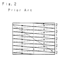
- Fig. 2 is a view explanatory of a principle of interlaced scanning of a television screen.
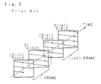
- Fig. 3 is a conceptional view showing a relation between fields and frames in a standard television system.
- Fig. 4 is a block diagram showing a construction of an apparatus corresponding to a first embodiment of the invention.
- Fig. 5 is a conceptional view showing a three-dimensional block according to a first embodiment of the invention.
- Fig. 6 is a picture showing one scene of natural mobile picture.
- Fig. 7 is a two-dimensional bit map used when a coefficient is coded.
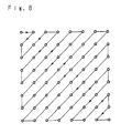
- Fig. 8 is a scanning view of a two-dimensional coefficient.
- Fig. 9 is a block diagram showing a construction of an apparatus corresponding to a second embodiment of the invention.
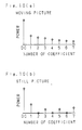
- Fig. 10 (a), (b) are power distribution views of coefficients after orthogonal transform.
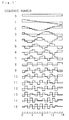
- Fig. 11 is a view showing base vectors of DCT.
- Fig. 12 (a), (b) are views showing one embodiment of weighting factor.
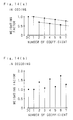
- Fig. 13 (a), (b) are views showing another embodiments of weighting factor.
- Fig. 14 (a), (b) are views showing still another embodiment of weighting factor.
- Fig. 15 is a block diagram showing a construction of an apparatus corresponding to a third embodiment of the invention.
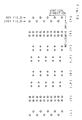
- Fig. 16 is a conceptional view showing picture elements explanatory of an operation of the third embodiment.
- Fig. 17 is a view showing an example of impulse response of odd-tap interpolation filter.
- Fig. 18 is a view showing an example of impulse response of even-tap interpolation filter.
- Fig. 19 is a conceptional view showing spectral distribution at the time of interlaced scanning.
- Fig. 20 is a conceptional view showing spectral distribution at the time of over-sampling.
- Fig. 21 is a conceptional view showing spectral distribution at the time when picture elements are coincided with each other.
- reference numeral 1 designates an input terminal for inputting a color television signal in NTSC system into an NTSC decoder 2.
- the NTSC decoder 2 separates the inputted color television signal into luminance signal (Y signal) and color difference signal (R-Y signal, B-Y signal) to output them to an analog-digital (hereinafter to be called A/D) converter 3.
- the A/D converter 3 converts inputted signal into digital signal and outputs the digital signal to a field memory 4.
- the field memory 4 bundles two-dimensional blocks in fields adjacent in temporal direction to compose a three-dimensional block (3-D block) and outputs data composed with 3-D block as a unit to a three-dimensional (3-D) orthogonal transforming circuit 5.
- the 3-D orthogonal transforming circuit 5 performs 3-D DCT (Discrete Cosine Transform), for example, on each 3-D block to obtain coefficients, and outputs the obtained coefficients to a coding unit 6.
- the coding unit 6 quantizes and codes the coefficients.
- the coded data is outputted through an output terminal 7.
- a coding system is composed of the above mentioned members 1 to 7.
- reference numerals 11 to 17 show the members composing a decoding system.
- Reference numeral 11 designates an input terminal for inputting the coded data to a decoding unit 12.
- the decoding unit 12 decodes the coded data to an original 3-D data and outputs the data to a 3-D inverse orthogonal transforming circuit 13.
- the 3-D inverse orthogonal transforming circuit 13 performs 3-D inverse DCT to obtain the original 3-D block and outputs it to a field memory 14.
- the field memory 14 return the 3-D block to the original field screen and outputs digital luminance signal (Y signal) and color difference signal (R-Y signal, B-Y signal) to a digital/analog (hereinafter to be called D/A) converter 15.
- the D/A converter 15 converts an inputted signal into an analog signal and outputs it to an NTSC encoder 16.
- the NTSC encoder 16 reproduces NTSC color television signal with luminance signal and color difference signal.
- the reproduced color television signal is outputted through an output terminal 17.
- a 3-D block is composed with horizontal direction 1 as primary direction, vertical direction 2 as secondary direction and field direction (temporal direction) 3 as tertiary direction. Concretely, it shows a block of 2 ⁇ 2 ⁇ 8.
- in odd-number field and in even-number field for example in (2i-1)th field and in 2i-th field, spatial positions of picture elements do not coincide with each other in vertical direction.
- the picture element in upper left of 2i-th field is positioned lower than that in upper left of (2i-1)-th field by 1/2 line.
- the data is quantized by the coding unit 6, then coded by using Huffman code-words and so on, and outputted from the output terminal 7.
- Fig. 6 is one scene of natural moving picture with a totem pole for a background.
- 3-D DCT of 8 ⁇ 8 ⁇ 8 picture elements is performed on data in a part marked with a rectangle in the vicinity of the center on the right side.
- 3-D DCT is performed on this data and the fractions of 5 and over are counted as a unit and the rest are cut away, to obtain coefficient as shown in Table 2(a), (b).
- the obtained coefficients are coded by using a coding bit map in Fig. 7 and a 2-D scanning in Fig. 8, the coding length of the 3-D data is 1902 bits.
- Fig. 7 an axis of abscissa shows levels of coefficients and axis of ordinate shows zero-run length, numerals in the figure showing code length.
- Fig. 8 is a scanning view frequently used in 2-D DCT, and in this embodiment, such 2-D scanning is to be repeated eight times.
- Table 3 shows original data of non-interlaced form.
- the coefficients obtained by performing 3D-DCT on the two blocks are shown in Table 4(a), (b).
- the code length in each block is 1,188 bits and 1,136 bits, the sum being 2,325 bits.
- FIG. 9 showing the construction of a coding/decoding apparatus according to a second embodiment, the parts with the same numbers as in Fig. 4 show the same members.
- the reference numeral 8 in the coding system designates a weighting and quantizing unit for quantizing the coefficients obtained in the 3-D orthogonal transforming circuit 5 after weighting.
- the weighting and quantizing unit 8 outputs the quantized data to a variable length coding unit 9.
- the variable length coding unit 9 performs variable length coding on the inputted data in the way that a brief code-word is assigned to data of high frequency by using Huffman code-words, for example.
- variable length decoding unit 18 in decoding system is a variable length decoding unit for decoding the variable-length-coded data into the original quantized data.
- the variable length decoding unit 18 outputs the quantized data to a weighting and inverse quantizing unit 19.
- the weighting and inverse quantizing unit 19 decodes the quantized data into the original data of coefficients.
- Fig. 10 shows power distribution of coefficients according to DCT of tertiary direction (temporal direction).
- Fig. 10(a) shows the case of moving picture and it is understood that each coefficient has power and much information content.
- Fig. 10(b) shows the case of still picture.
- N point DCT is defined by the following equations. here, when odd fields and even fields are considered separately, Y(i) is expressed in the following equation.
- weighting and quantizing unit 8 weighting is performed only on even-number-th coefficients with no information of still picture, to quantize them equally and roughly.
- Fig. 12(a) an example of weighting factor in weighting is shown.
- still picture as this weighting is performed on coefficients whose values are originally zero, there is no influence.
- moving picture as coefficient is converted into zero or small number by the weighting, information content is reduced by the operation of the variable length coding unit 9, in which Huffman code-words are used.
- variable-length-coded data by the variable length coding unit 9 is outputted from the output terminal 7.
- NTSC color television signal is obtained and outputted from the output terminal 17 by performing a totally inverse process to that of the above-mentioned coding system.
- Fig. 12(b) an example of weighting factor used in decoding is shown.
- weighting factor used in coding and decoding is shown in Fig. 13 and Fig. 14.
- each weighting is performed in the way that even-number-th coefficients are more roughly quantized than odd-number-th coefficients. Accordingly, information content can be largely reduced at the time of moving picture, restricting image deterioration of still picture to a slight degree.
- weighting and quantizing is performed only on even-number-th coefficients by which pseudo-moving part does not appear or weighting at lower rate and more roughly quantizing is performed on coefficients by which pseudo-moving part does not appear than on odd-number-th coefficients by which pseudo-moving part appears. Accordingly information content at the time of moving picture is largely reduced without judging whether the picture is moving or still and without deterioration of quality of still picture.
- Reference numeral 10 designates a vertical interpolation filter which performs inter-picture elements calculation in vertical direction in each field of digital luminance signal and color difference signal outputted from the A/D converter 3 and make the spatial positions of picture elements in odd-fields and those in even-fields coincide with each other.
- the vertical interpolation filter 10 outputs data to the field memory 4 after the positions are made coincided.
- Reference numeral 20 in the decoding system is a vertical interpolation filter which reverses the original digital data of picture element from the data, in which positions of picture elements are made coincided, that is outputted from the field memory 14.
- the vertical interpolation filter 20 outputs the decoded data of picture element to the D/A converter 15.
- Fig. 16 is a conceptional view showing picture elements explanatory of the operation in the third embodiment.
- the luminance signal and the color difference signal are converted into digital signals by the A/D converter 3.
- the spatial positions of picture elements (shown by ⁇ ) of them in odd field add those in even field, for example, those in (2i -1)-th field and those in 2i-th field, do not coincide with each other as shown in Fig. 16(a).
- Picture elements in even field are positioned 1/2 line lower than those in odd field.
- a method of over sampling is used.
- zero data is inserted to every other element in vertical direction.
- Mark ⁇ in Fig. 16 (b) shows the inserted zero data.
- interpolated data is obtained in the inserted zero data and the number of picture elements are made double.
- an interpolation filter an odd-tap filter with impulse response shown in Fig. 17, for example, can be used.
- the obtained interpolated data is removed so that the picture elements with the same spatial positions are left, and the data after removal is outputted to the field memory 4.
- 3-D block with plurality of picture elements as a unit is constructed at the field memory 4 with horizontal direction for a primary direction, vertical direction for a secondary direction and temporal direction for a tertiary direction. And 3-D DCT is performed on every constructed 3-D block in the 3-D orthogonal transforming circuit 5.
- the 3-D block data on which 3-D inverse orthogonal transform has been performed becomes field data (Fig. 16 (d)) in which spatial positions of picture elements coincide with each other in the field memory 14.
- field data Fig. 16 (d)
- zero data is inserted to be passed through an interpolation filter, data as shown in Fig. 16 (e) is obtained.
- digital signal Fig. 16 (f) in interlaced scanning form, same as that in Fig. 16 (a), is obtained.
- Fig. 19 is a view at the time of interlaced scanning corresponding to Fig. 16 (a). The image is woven in oblique direction due to the effect of offset sampling.
- the state in Fig. 20 corresponds to that in Fig. 16 (b), in which the number of picture elements are doubled by two-times over sampling, and vertical lower components is extracted by a vertical low pass filter.
- the state in Fig. 21 corresponds to that in Fig. 16 (C), in which number of picture elements becomes the same as original by 1/2 removal.
- Fig. 16 (d), (e), (f) respectively correspond to Fig. 21, 20, 19, original digital signal in interlaced scanning form being decoded.
- immediate position coincidence can be performed by using an all pass filter.
- it can be performed by applying a filter having response with mark ⁇ to odd field and a filter having response with a mark ⁇ to even field.
- a filter whose tap number is even can be processed in the same way.
- an even-tap interpolation filter there is one which has impulse response as shown in Fig. 18.
- a signal (Fig. 16 (a)) in interlaced scanning form when zero data is inserted (Fig. 16 (b)) to every other element in vertical direction to be passed through an interpolation filter in the same way as in odd-tap filter, interpolation data by two-times over sampling can be obtained.
- the center of gravity of the even-tap filter is not positioned on picture element but on the center between adjacent picture elements, the positions of picture elements after filtering are to be moved by 1/4 line. By 1/2 removal, picture elements having the same spatial positions are obtained, as shown in Fig. 16 (c'). The frequency spectrum at this time is not different from that of odd-tap filter at all.
- FIG. 16 (d') A signal inputted to an interpolation filter at the time of decoding is shown in Fig. 16 (d').
- Fig. 16 (e) When zero data is inserted and filtered, as it dislocates by 1/4 line in the same way as in coding, a signal shown in Fig. 16 (e) is obtained.
- Fig. 16 (f) When offset sampling is performed in the same way as odd-tap filter, the original digital signal (Fig. 16 (f)) in interlaced scanning form is obtained.
Abstract
Description
- This invention relates to a coding method and coding apparatus for coding digital video signal by reducing it.
- As conventional methods of coding digital video signal, there are ones disclosed in Japanese Patent Application Laid-Open No. 1-253382 (1989) and U.S. Patent No. 4,394,774. In the following, explanation will be given referring to these official reports.
- Transmitting or recording digital video signal can reduce channel noise or reading noise in quality of a displayed image, and these digital signals are easily transmitted by digital network of telephone type. In spite of this, digitization of sequence of television image is carried out at such high speed that digitized color television signal cannot be directly transmitted or recorded generally by an existing carrier. According to a notice 601 by CCIR, digitization rate of color television signal is 216Mbtis/s. Therefore, in order to apply the digitized color television signal to actual transmitting speed and recording speed, it is important to reduce the digitization rate.
- In U.S. Patent No. 4,394,774, a method of reducing the digitization rate to a
factor 10 to 20, that is, 1/10 to 1/20 is mentioned. The method based upon orthogonal transform can compress redundancy by using the redundancy of neighboring picture elements in the image. This method is characterized by performing orthogonal transform, which makes picture elements of a block decorrelating by dividing an image into blocks with same sizes and concentrating energy to small number of picture elements. - In order to gain equivalent information reduction from image-to image redundancy existing in a still part of an image, this method is often combined with an image-to image prediction technique.
- According to this technique, either a block itself is transmitted (intra-frame mode) or a difference between this block and a block with a same spatial position as a preceding image after coding/decoding is transmitted (inter-frame mode), accordingly a block with a minimum energy is transmitted.
- If this image-to-image prediction introduces time-recursivity of coding, in other words, if the decoded preceding image can be used, only decoding the image signal with usual reproducing mode is possible by the prediction. This is characterized that errors existing in receiving video signal or in reading a band are to exist in various images. In fact, there is a danger that various errors appear in an image as long as the block in which this error appears is coded with inter-frame mode.
- Moreover, the recursivity is not compatible with a consumer's video recording, that is, home video recording. Because a random access to an image is excepted, this random access being necessary to realize "quick search mode". Sometimes, to improve on the fault one image among N images is coded with intra-frame mode. But as this method degrade quality of a displayed image, the number N should be large so that the degradation may be restricted, resulting in the limited improvement.
- Japanese Patent Application Laid-Open No. 1-253382 (1989) provides a method of coding video signal by which video signal can be coded by image-to-image correlation without introducing the image-to-image recursivity. That is, this official report provides a method which is compatible with a consumer's video recording and is not sensitive to channel error.
- In order to realize the coding method, the coding apparatus is provided with the following steps;
- (a) a preliminary step which is an estimation of principal movement from one image to another for relating displacement vector to each image concerning a preceding image, the principal vector being a vector whose image-to-image difference is minimum,
- (b) a preliminary step which is a scan conversion for prescribing a form of three-dimensional (3-D) block, by dividing sequence of video signals corresponding to image into groups each of which corresponds to N continuous images and by prescribing a three dimensional group including M lines and P picture elements in every line in an image plane of a group on one hand and in N continuous planes corresponding to N images of a group on the other hand, N two-dimensional blocks with M lines and P picture elements which compose each three-dimensional block of a same group being spatially shifted from one image to another by a displacement vector which has been estimated as to each image.
- The method gives a possibility of using a temporal redundancy of a signal, thanks to decorrelation realized by orthogonal transform of a still part of an image without substantial displacement. This method can be applied to the case of a sight or a general movement of a camera and even to the case where the movement effects almost all the parts of the sight. In the last two cases, this method is superior to that which uses inter-frame mode and intra-frame mode. Because it uses inter-frame correlation and at the same time inter-frame/intra-frame process does not take these displacements into consideration. Moreover, as the effect is limited to N images, this process does not introduce any image-to-image recursivity at the time of coding, ensuring compatibility of satisfying immunity to noise with "quick search mode" provided in a video recorder.
- If decrease of speed of video signal in a non-interlaced image form is used, this process is especially effective. If a usable signal is interlaced, the form thereof is converted before coding, leading to produce non-interlaced video signal. Accordingly, as shown in Fig. 1, each image is composed of each frame, and a three-dimensional block is composed by taking one-dimensional direction in the horizontal direction, two-dimensional direction in the vertical direction, and three dimensional direction in the temporal direction, and a redundant component of an image signal is to be reduced by orthogonal transform.
- But in actual television screen, interlaced scanning form is adopted, as shown in Fig. 2. In transmitting data of moving picture, this method is profitable of preventing flickering without increasing information content to be transmitted. Therefore, scanning of one screen is finished with a half number of scanning lines shown in Fig. 2. At the next screen, reduction of vertical resolution of an image is restricted by scanning lines which did not scanned in a previous screen. By this interlaced scanning form, as the number of screens transmitted in a same time becomes double of that at the time of sequential scanning, generation of flickers is restricted. This roughly scanned screen is called a field, and continuous two fields forms a frame, as shown in Fig. 3, the scanning rate being 60 fields by NTSC (National Television System Committee) method.
- According to a conventional coding method, as a three-dimensional block is composed by a non-interlaced signal, redundancy of an image signal could not always be reduced effectively as to interlaced image signal. Especially, when an interlaced image signal which has a large motion is made non-interlaced form, effective decreasing of redundancy of an image signal can not be obtained as two-dimension in which spatial displacement and time displacement is mixed is constructed.
- By the way, in the case of coding digital video signal in interlaced scanning form, spatial displacement in adjacent interfields is converted to time displacement due to the effect of the interlaced scanning form and pseudo part appears even in a case of a complete still picture. Accordingly, when weighting and quantizing is performed on high coefficient after orthogonal transform carried out in the temporal direction in order to reduce information content at the time of moving picture, the weighting and quantizing is also carried out in the pseude-moving part, resulting in deterioration of image quality of still picture at decoding side. In order to solve these problems, it is necessary to judge whether the picture is moving or still on every 3-D block and to perform weighting and quantizing of different level corresponding to a moving picture or a still picture.
- One object of the present invention is to provide a coding method and a coding apparatus capable of effectively reducing redundancy of video signal in interlaced scanning form.
- Another object of the invention is to provide a coding method and a coding apparatus capable of reducing information content at the time of moving picture without judging whether the picture is moving or still.
- Still another object of the invention is to provide a coding method and a coding apparatus capable of reducing information content at the time of moving picture without deterioration of image quality of still picture at decoding side.
- Further object of the invention is to provide a coding method and a coding apparatus capable of more effectively reducing redundancy of video signal in interlaced scanning form by making spatial positions of picture elements in odd-number fields and those in even-number fields coincide with each other.
- In one coding method of the invention, as to video signal in interlaced scanning from, a two-dimensional block is composed in each field, and the odd-number and the even-number fields are bundled in temporal direction to compose a three- dimensional block in every spatially adjacent picture element, and coding are performed by orthogonal transform on every 3-D block. When compared with a conventional example, it has more accurate signal composition in temporal direction, being capable of reducing video signal.
- In another coding method of the invention, quantizing is performed after weighting, on a coefficient by which pseudo-moving part due to the effect of interlaced scanning does not appear, and quantizing is performed intact on a coefficient by which pseudo-moving part appears. At this time, in the case of still picture, as weighting is performed on a coefficient whose value is originally zero, data is not lost at all, and there is no deterioration in image quality of still picture at decoding side. On the other hand, in the case of moving picture, as the coefficient is converted into zero or a small number by weighting, the information content is reduced.
- In still another coding method of the invention, weighting at lower rate and rougher quantizing are performed on a coefficient by which pseudo moving part does not appear, than on a coefficient in which pseudo moving part appears due to an effect of interlaced scanning. At this time, in the case of still picture, as the weighting at lower rate is performed a coefficient whose value is originally zero, degree of information reduction is small as a whole. On the other hand, in the case of moving picture, as the coefficient is converted into zero or a small number by weighting at lower rate, the information content is reduced largely.
- In further coding method of the invention, as to digital video signal in interlaced scanning form, after the positions of picture elements in odd-fields and those in even-fields are coincided with each other in the vertical direction by performing intra-field picture elements calculation, operations such as orthogonal transform and filtering are performed on picture elements of a plurality of fields. Concretely, after the positions of picture elements in odd-number fields and those in even-number fields are coincided with each other in vertical direction, a three-dimensional block comprising of horizontal direction, vertical direction and temporal direction is composed with every plurality of picture elements, three-dimensional orthogonal transform being performed on the three-dimensional block. As the positions of picture elements in odd-number fields and those in even-number fields are coincided with each other in two-dimensional space, the signal composition becomes more accurate to temporal direction, thereby larger information reduction being accomplished by interfield picture elements calculation. The above and further objects and features of the invention will more fully be apparent from the following detailed description with accompanying drawings.
- Fig. 1 is a conceptional view showing a conventional three-dimensional block in non-interlaced form.
- Fig. 2 is a view explanatory of a principle of interlaced scanning of a television screen.
- Fig. 3 is a conceptional view showing a relation between fields and frames in a standard television system.
- Fig. 4 is a block diagram showing a construction of an apparatus corresponding to a first embodiment of the invention.
- Fig. 5 is a conceptional view showing a three-dimensional block according to a first embodiment of the invention.
- Fig. 6 is a picture showing one scene of natural mobile picture.
- Fig. 7 is a two-dimensional bit map used when a coefficient is coded.
- Fig. 8 is a scanning view of a two-dimensional coefficient.
- Fig. 9 is a block diagram showing a construction of an apparatus corresponding to a second embodiment of the invention.
- Fig. 10 (a), (b) are power distribution views of coefficients after orthogonal transform.
- Fig. 11 is a view showing base vectors of DCT.
- Fig. 12 (a), (b) are views showing one embodiment of weighting factor.
- Fig. 13 (a), (b) are views showing another embodiments of weighting factor.
- Fig. 14 (a), (b) are views showing still another embodiment of weighting factor.
- Fig. 15 is a block diagram showing a construction of an apparatus corresponding to a third embodiment of the invention.
- Fig. 16 is a conceptional view showing picture elements explanatory of an operation of the third embodiment.
- Fig. 17 is a view showing an example of impulse response of odd-tap interpolation filter.
- Fig. 18 is a view showing an example of impulse response of even-tap interpolation filter.
- Fig. 19 is a conceptional view showing spectral distribution at the time of interlaced scanning.
- Fig. 20 is a conceptional view showing spectral distribution at the time of over-sampling.
- Fig. 21 is a conceptional view showing spectral distribution at the time when picture elements are coincided with each other.
- In Fig. 4 which shows the construction of a coding/decoding apparatus according to a first embodiment,
reference numeral 1 designates an input terminal for inputting a color television signal in NTSC system into anNTSC decoder 2. TheNTSC decoder 2 separates the inputted color television signal into luminance signal (Y signal) and color difference signal (R-Y signal, B-Y signal) to output them to an analog-digital (hereinafter to be called A/D)converter 3. The A/D converter 3 converts inputted signal into digital signal and outputs the digital signal to afield memory 4. Thefield memory 4 bundles two-dimensional blocks in fields adjacent in temporal direction to compose a three-dimensional block (3-D block) and outputs data composed with 3-D block as a unit to a three-dimensional (3-D) orthogonal transformingcircuit 5. The 3-D orthogonal transformingcircuit 5 performs 3-D DCT (Discrete Cosine Transform), for example, on each 3-D block to obtain coefficients, and outputs the obtained coefficients to acoding unit 6. Thecoding unit 6 quantizes and codes the coefficients. The coded data is outputted through anoutput terminal 7. A coding system is composed of the above mentionedmembers 1 to 7. - In addition,
reference numerals 11 to 17 show the members composing a decoding system.Reference numeral 11 designates an input terminal for inputting the coded data to adecoding unit 12. Thedecoding unit 12 decodes the coded data to an original 3-D data and outputs the data to a 3-D inverse orthogonal transformingcircuit 13. The 3-D inverse orthogonal transformingcircuit 13 performs 3-D inverse DCT to obtain the original 3-D block and outputs it to afield memory 14. Thefield memory 14 return the 3-D block to the original field screen and outputs digital luminance signal (Y signal) and color difference signal (R-Y signal, B-Y signal) to a digital/analog (hereinafter to be called D/A)converter 15. The D/A converter 15 converts an inputted signal into an analog signal and outputs it to anNTSC encoder 16. TheNTSC encoder 16 reproduces NTSC color television signal with luminance signal and color difference signal. The reproduced color television signal is outputted through anoutput terminal 17. - In the following, explanation will be given on the operation. Generally, in reducing image information, it is convenient to deal with luminance signal and chrominance signal independently. Accordingly, after the NTSC color television signal inputted from the
input terminal 1 is separated by theNTSC decoder 2 into luminance signal (Y signal) color difference signal (R-Y signal, B-Y signal), each of these signals is digitized by the A/D converter 3. The sampling frequency of Y signal is 13.5MHz, those of R-Y signal and B-Y signal are both 6.75MHz. Therefore, in the case of NTSC color television signal, effective sample number per one horizontal line of Y signal is 720, those of R-Y signal and B-Y signal are both 360, 262.5 horizontal lines composing one field. Among these, data of eight fields are taken into thefield memory 4, effective lines, 250 horizontal lines for example, composing one field. - And while the data of the next eight fields is being taken in, data of 3-D block as shown in Fig. 5 is outputted from the
field memory 4 to the 3-D orthogonal transformingcircuit 5. - In Fig. 5, a 3-D block is composed with
horizontal direction ① as primary direction,vertical direction ② as secondary direction and field direction (temporal direction) ③ as tertiary direction. Concretely, it shows a block of 2 × 2 × 8. In addition, as shown in Fig. 5, in odd-number field and in even-number field, for example in (2i-1)th field and in 2i-th field, spatial positions of picture elements do not coincide with each other in vertical direction. The picture element in upper left of 2i-th field is positioned lower than that in upper left of (2i-1)-th field by 1/2 line. After 3-D DCT is performed on the data transmitted with such 3-D block as a unit, in the 3-D orthogonal transformingcircuit 5, the data is quantized by thecoding unit 6, then coded by using Huffman code-words and so on, and outputted from theoutput terminal 7. - While in the decoding system from the
input terminal 11 to theoutput terminal 17, totally inverse process to that of the above-mentioned coding system from theinput terminal 1 to theoutput terminal 7 is carried out, and the original NTSC color television signal is obtained and outputted from theoutput terminal 17. - Here, it will be described that the information reduction can be carried out according to the above-mentioned method. Fig. 6 is one scene of natural moving picture with a totem pole for a background. Explanation will be given on the example that 3-D DCT of 8 × 8 × 8 picture elements is performed on data in a part marked with a rectangle in the vicinity of the center on the right side. Table 1 shows the data which is obtained by quantizing luminance signals of the fields from t = 0 to t = 7 in the part marked with a rectangle into 8 bits uniformly. 3-D DCT is performed on this data and the fractions of 5 and over are counted as a unit and the rest are cut away, to obtain coefficient as shown in Table 2(a), (b). When the obtained coefficients are coded by using a coding bit map in Fig. 7 and a 2-D scanning in Fig. 8, the coding length of the 3-D data is 1902 bits.
- In Fig. 7, an axis of abscissa shows levels of coefficients and axis of ordinate shows zero-run length, numerals in the figure showing code length. Fig. 8 is a scanning view frequently used in 2-D DCT, and in this embodiment, such 2-D scanning is to be repeated eight times.
- While the same data has been converted into non-interlaced form to be coded as conventional way. Table 3 shows original data of non-interlaced form. In this case, there are two 3-D blocks of 8 × 8 × 4 picture elements. The coefficients obtained by performing 3D-DCT on the two blocks are shown in Table 4(a), (b). When the coefficients are coded by using the coding bit map in Fig. 7 and the 2-D scanning in Fig. 8, the code length in each block is 1,188 bits and 1,136 bits, the sum being 2,325 bits.
- As mentioned above, when compared with a conventional example, about 16% of information reduction has been accomplished in this embodiment. According to this embodiment, when information content is converted into a transmitting rate by performing coding on a four-frame image in Fig. 6, about 25.3Mbps is obtained. In the same way, in a conventional example, transmitting rate is about 30.2Mbps. From these facts, it can be understood that information reduction can be accomplished not only in a part of an image but in a whole image.
- Next, explanation will be given on the second embodiment of the invention. This is an example of coding the obtained coefficients after weighting in order to reduce information content. In Fig. 9 showing the construction of a coding/decoding apparatus according to a second embodiment, the parts with the same numbers as in Fig. 4 show the same members. The
reference numeral 8 in the coding system designates a weighting and quantizing unit for quantizing the coefficients obtained in the 3-D orthogonal transformingcircuit 5 after weighting. The weighting andquantizing unit 8 outputs the quantized data to a variablelength coding unit 9. The variablelength coding unit 9 performs variable length coding on the inputted data in the way that a brief code-word is assigned to data of high frequency by using Huffman code-words, for example. And reference numeral 18 in decoding system is a variable length decoding unit for decoding the variable-length-coded data into the original quantized data. The variablelength decoding unit 18 outputs the quantized data to a weighting andinverse quantizing unit 19. The weighting andinverse quantizing unit 19 decodes the quantized data into the original data of coefficients. - Next, explanation will be given on the operation. Here, explanation will be concentrated on the operation of weighting different from that of the first embodiment. In the same way as in the first embodiment, the data with 3-D block as a unit as shown in Fig. 5 is outputted from the
field memory 4 to the 3-D orthogonal transformingcircuit 5, and 3-D DCT is performed on the data. Fig. 10 shows power distribution of coefficients according to DCT of tertiary direction (temporal direction). Fig. 10(a) shows the case of moving picture and it is understood that each coefficient has power and much information content. Fig. 10(b) shows the case of still picture. Originally there is no information change in temporal direction in still picture, due to interlaced scanning, spatial displacement is converted into temporal displacement, power appears on odd-number-th coefficients when DC component is made 0-th. This is related to a degree N of base vector of DCT. In Fig. 11, base vectors of DCT when N = 16 are shown. - Here, the reason why power appears only on odd-number-th coefficients will be explained on the basis of definition formula of DCT. N point DCT is defined by the following equations.


here, when odd fields and even fields are considered separately, Y(i) is expressed in the following equation.
- In the case of still picture, as the image signals in even fields are same with each other and those in odd fields are also same with each other. x(0) = x(2) = ,..., = x(N-2) and x(1) = x(3) = , ..., = x(N-1). When this is utilized, y(i) is further expressed by the following equation.

- In addition, in cosine function, as


- In this way, even-number-th coefficients except DC component are zero, and power appears in odd-number-th coefficients.
- In the weighting and
quantizing unit 8, weighting is performed only on even-number-th coefficients with no information of still picture, to quantize them equally and roughly. In Fig. 12(a), an example of weighting factor in weighting is shown. In the case of still picture, as this weighting is performed on coefficients whose values are originally zero, there is no influence. In the case of moving picture, as coefficient is converted into zero or small number by the weighting, information content is reduced by the operation of the variablelength coding unit 9, in which Huffman code-words are used. - The variable-length-coded data by the variable
length coding unit 9 is outputted from theoutput terminal 7. - While in the decoding system from the
input terminal 11 to theoutput terminal 17, NTSC color television signal is obtained and outputted from theoutput terminal 17 by performing a totally inverse process to that of the above-mentioned coding system. In Fig. 12(b), an example of weighting factor used in decoding is shown. - Another example of weighting factor used in coding and decoding is shown in Fig. 13 and Fig. 14. In this example, each weighting is performed in the way that even-number-th coefficients are more roughly quantized than odd-number-th coefficients. Accordingly, information content can be largely reduced at the time of moving picture, restricting image deterioration of still picture to a slight degree.
- In addition, although explanation is given on the example using 3-D orthogonal transform in the second embodiment, it is a matter of course that a method of processing 2-D space is optional, as long as orthogonal transform is performed in temporal direction.
- In the second embodiment as above-mentioned, weighting and quantizing is performed only on even-number-th coefficients by which pseudo-moving part does not appear or weighting at lower rate and more roughly quantizing is performed on coefficients by which pseudo-moving part does not appear than on odd-number-th coefficients by which pseudo-moving part appears. Accordingly information content at the time of moving picture is largely reduced without judging whether the picture is moving or still and without deterioration of quality of still picture.
- In the above-mentioned first and second embodiments, in the case where 3-D block is constructed by signals in interlaced scanning form, as the spatial positions of picture elements in odd-fields and those in even-fields do not coincide with each other in vertical direction, there still is a possibility that redundancy can be further reduced. In the third embodiment of the invention, inter-picture elements calculation is performed in vertical direction in each field on digital video signal in interlaced scanning form, thereby spatial positions of picture elements in odd-fields and those in even-fields are coincided with each other, then 3-D orthogonal transform is performed thereon.
- In Fig. 15 showing the construction of coding/decoding apparatus according to the third embodiment, the parts with the same numbers as those in Fig. 4 are the same members.
Reference numeral 10 designates a vertical interpolation filter which performs inter-picture elements calculation in vertical direction in each field of digital luminance signal and color difference signal outputted from the A/D converter 3 and make the spatial positions of picture elements in odd-fields and those in even-fields coincide with each other. Thevertical interpolation filter 10 outputs data to thefield memory 4 after the positions are made coincided.Reference numeral 20 in the decoding system is a vertical interpolation filter which reverses the original digital data of picture element from the data, in which positions of picture elements are made coincided, that is outputted from thefield memory 14. Thevertical interpolation filter 20 outputs the decoded data of picture element to the D/A converter 15. - Next, explanation will be given on the operation. As the operation of the embodiment is same as that of the above-mentioned first embodiment except making the positions of picture elements coincide in the
vertical interpolation filter 10 and reversion of the original data of picture element in thevertical interpolation filter 20, explanation will be concentrated here on the different points. - Fig. 16 is a conceptional view showing picture elements explanatory of the operation in the third embodiment.
- The luminance signal and the color difference signal are converted into digital signals by the A/
D converter 3. The spatial positions of picture elements (shown by ○) of them in odd field add those in even field, for example, those in (2i -1)-th field and those in 2i-th field, do not coincide with each other as shown in Fig. 16(a). Picture elements in even field are positioned 1/2 line lower than those in odd field. - In order to perform position coincidence in the
vertical interpolation filter 10, a method of over sampling is used. In order to double the number of picture elements, zero data is inserted to every other element in vertical direction. Mark □ in Fig. 16 (b) shows the inserted zero data. When the data is passed through a low pass filter for interpolation, interpolated data is obtained in the inserted zero data and the number of picture elements are made double. As an interpolation filter, an odd-tap filter with impulse response shown in Fig. 17, for example, can be used. As shown in Fig. 16 (c), the obtained interpolated data is removed so that the picture elements with the same spatial positions are left, and the data after removal is outputted to thefield memory 4. In thefield memory 4, 3-D block with plurality of picture elements as a unit is constructed at thefield memory 4 with horizontal direction for a primary direction, vertical direction for a secondary direction and temporal direction for a tertiary direction. And 3-D DCT is performed on every constructed 3-D block in the 3-D orthogonal transformingcircuit 5. - In the decoding system, the 3-D block data on which 3-D inverse orthogonal transform has been performed becomes field data (Fig. 16 (d)) in which spatial positions of picture elements coincide with each other in the
field memory 14. Here, in order to reproduce the original data of picture element, in the same way as in the coding system, zero data is inserted to be passed through an interpolation filter, data as shown in Fig. 16 (e) is obtained. Moreover, when the data marked with □ is removed, digital signal (Fig. 16 (f)) in interlaced scanning form, same as that in Fig. 16 (a), is obtained. - Above description is conceptionally shown on frequency axes in Fig. 19, 20, 21. In each figure, axis of ordinate shows frequency in vertical direction, and axis of abscissa shows frequency in temporal direction. Fig. 19 is a view at the time of interlaced scanning corresponding to Fig. 16 (a). The image is woven in oblique direction due to the effect of offset sampling. The state in Fig. 20 corresponds to that in Fig. 16 (b), in which the number of picture elements are doubled by two-times over sampling, and vertical lower components is extracted by a vertical low pass filter. Moreover the state in Fig. 21 corresponds to that in Fig. 16 (C), in which number of picture elements becomes the same as original by 1/2 removal. As the high components returned in vertical direction are separated well in temporal direction, it is profitable for information reduction. While in the decoding system, as the process thereof is inverse to that of coding system, Fig. 16 (d), (e), (f) respectively correspond to Fig. 21, 20, 19, original digital signal in interlaced scanning form being decoded.
- In the above example, for making the positions of picture elements coincide with each other, a method of over sampling and a method of 1/2 removal are used, but immediate position coincidence can be performed by using an all pass filter. For example, in Fig. 17, it can be performed by applying a filter having response with mark ● to odd field and a filter having response with a mark ○ to even field.
- Next, it is shown that a filter whose tap number is even can be processed in the same way. As an example of an even-tap interpolation filter, there is one which has impulse response as shown in Fig. 18. As to a signal (Fig. 16 (a)) in interlaced scanning form, when zero data is inserted (Fig. 16 (b)) to every other element in vertical direction to be passed through an interpolation filter in the same way as in odd-tap filter, interpolation data by two-times over sampling can be obtained. Here, as the center of gravity of the even-tap filter is not positioned on picture element but on the center between adjacent picture elements, the positions of picture elements after filtering are to be moved by 1/4 line. By 1/2 removal, picture elements having the same spatial positions are obtained, as shown in Fig. 16 (c'). The frequency spectrum at this time is not different from that of odd-tap filter at all.
- A signal inputted to an interpolation filter at the time of decoding is shown in Fig. 16 (d'). When zero data is inserted and filtered, as it dislocates by 1/4 line in the same way as in coding, a signal shown in Fig. 16 (e) is obtained. When offset sampling is performed in the same way as odd-tap filter, the original digital signal (Fig. 16 (f)) in interlaced scanning form is obtained.
- In addition, in the same way as in the case where odd-tap filter is used, in the case where even-tap filter is used, immediate position coincidence of picture elements in odd field with those in even field can be performed. If response with a mark ● in Fig. 18 is applied to odd field and response with a mark ○ to even field respectively.
- As mentioned above, in the third embodiment, as to video signal in interlaced scanning form, positions of picture elements in odd field and those in even field are made coincide with each other in 2-D space by a vertical interpolation filter intrafield, then a 3-D block is composed by bundling odd and even field in temporal direction, and orthogonal transform is performed on it to code it, therefore information reduction is performed more obviously as to video signal in interlaced scanning form than the first embodiment. In addition, it is a matter of course that it is also profitable to combine the third embodiment with the second embodiment.
- In addition, in the above embodiments, although explanation is given on a "so-called" signal of 4:2:2 component which samples Y signal with 13.5MHz, R-Y signal and B-Y signal with 6.75MHz, the frequency for sampling is not limited to those above-mentioned.
- As this invention may be embodied in several forms without departing from the spirit of essential characteristics thereof, the present embodiment is therefore illustrative and not restrictive.


Claims (17)
- A coding method for coding a digital video signal of interlaced type, comprising:
a step of constructing three-dimensional blocks for every plurality of picture elements, picture elements in the horizontal direction of each field being primary components, picture elements in the vertical direction of each field being secondary components, picture elements of plurality of fields having nearly coincidental two-dimensional spatial position being tertiary components;
a step of performing orthogonal transform to each constructed three-dimensional block thereby to obtain coefficients; and
a step of coding the obtained coefficients. - A coding method as set forth in Claim 1, wherein said orthogonal transform is DCT (Discrete Cosine Transform).
- A coding method for coding a digital video signal of interlaced type, comprising:
a step of constructing two-dimensional blocks for every picture elements in each field;
a step of constructing a three-dimensional block by bundling two-dimensional blocks of plurality of fields having nearly coincidental two-dimensional spatial position;
a step of performing orthogonal transform to the constructed three-dimensional block thereby to obtain coefficients; and
a step of coding the obtained coefficients. - A coding method for coding digital video signal of interlaced type, comprising:
a step of formatting said digital video signal at least in temporal direction thereby to construct blocs;
a step of performing orthogonal transform to each constructed block thereby to obtain coefficients; and
a step of quantizing and coding the obtained coefficients,
wherein
coefficients whose values are zero when the formatted signal corresponds to a still picture are performed weighting before quantizing. - A coding method as set forth in Claim 4, wherein said orthogonal transform is DCT (Discrete Cosine Transform).
- A coding method as set forth in Claim 5, wherein said interlaced type is 2:1 interlaced one, and when digital video signal of 2N fields (N: a natural number) is performed DCT thereby to obtain zero-th to (2N-1)-th coefficients, 2m-th coefficients (m: a natural number less than N) are performed weighting and quantized.
- A coding method for coding a digital video signal of interlaced type, comprising:
a step of constructing three-dimensional blocks for every plurality of picture elements, picture elements in the horizontal direction of each field being primary components, picture elements in the vertical direction of each field being secondary components, picture elements of plurality of fields having nearly coincidental two-dimensional spatial position being tertiary components;
a step of performing orthogonal transform to each constructed three-dimensional block thereby to obtain coefficients; and
a step of quantizing and coding the obtained coefficients,
wherein
coefficients whose value are zero when the three-dimensional formatted signal corresponds to a still picture are performed weighting before quantizing. - A coding method for coding a digital video signal of interlaced type, comprising:
a step of formatting said digital video signal at least in temporal direction thereby to construct blocks;
a step of performing orthogonal transform to each constructed block thereby to obtain coefficients;
a step of weighting and quantizing the obtained coefficients thereby to obtain quantized data; and
a step of coding the quantized data,
wherein
coefficients whose values are zero when the formatted signal corresponds to a still picture are performed weighting with lower rate than coefficients whose values are not zero when the formatted signal corresponds to a still picture. - A coding method as set forth in Claim 8, wherein said orthogonal transform is DCT (Discrete Cosine Transform).
- A coding method as set forth in Claim 9, wherein said interlaced type is 2:1 interlaced one, and when digital video signal of 2N fields (N: natural number) is performed DCT thereby to obtain zero-th to (2N-1)-th coefficients, 2m-th coefficients (m: a natural number less than N) are performed weighting with lower rate than (2k-1)-th coefficients(k: a natural number not larger than N.)
- A coding method for coding a digital video signal of interlaced type, comprising:
a step of constructing three-dimensional blocks for every plurality of picture elements, picture elements in the horizontal direction of each field being primary components, picture elements in the vertical direction of each field being secondary components, picture elements of plurality of fields having nearly coincidental two-dimensional spatial position being tertiary components;
a step of performing orthogonal transform to each constructed three-dimensional block thereby to obtain coefficients;
a step of weighting and quantizing the obtained coefficients thereby to obtain quantized data; and
a step of coding the quantized data,
wherein
coefficients whose values are zero when the three-dimensional formatted signal corresponds to a still picture are performed weighting with lower rate than coefficients whose values are not zero when the formatted signal corresponds to a still picture. - A coding method for coding a digital video signal of interlaced type, comprising:
a first step of executing operation by use of picture elements in the vertical direction in each field thereby to make the spatial position of picture elements in odd-number field and that in even-number field same;
a second step of executing operation as to picture elements of plurality of fields having the same spatial position. - A coding method as set forth in Claim 12, wherein said first step comprises the following steps:
a step of inserting picture elements with zero level every other picture elements in the vertical direction so that the number of picture elements becomes double;
a step of passing data after inserted zero picture element through a interpolation filter; and
a step of removing picture elements thereby to make the spatial position of picture elements in odd-number field and that in even-number field same. - A coding method for coding a digital video signal of interlaced type, comprising:
a step of executing operation by use of picture elements in the vertical direction in each field thereby to make the spatial position of picture elements in odd-number field and that in even-number field same;
a step of constructing three-dimensional blocks for every plurality of picture elements, picture elements in the horizontal direction of each field being primary components, picture elements in the vertical direction of each field being secondary components, picture elements of plurality of fields having nearly coincidental two-dimensional spatial position being tertiary components;
a step of performing orthogonal transform to each constructed three-dimensional block thereby to obtain coefficients:; and
a step of coding the obtained coefficients. - A coding apparatus for coding a digital video signal of interlaced type, comprising:
means for constructing three-dimensional blocks for every plurality of picture elements, picture elements in the horizontal direction of each field being primary components, picture elements in the vertical direction of each field being secondary components, picture elements of plurality of fields having nearly coincidental two-dimensional spatial position being tertiary components;
means for performing orthogonal transform to each constructed three-dimensional block thereby to obtain coefficients; and
means for coding the obtained coefficients. - A coding apparatus for coding a digital video signal of interlaced type, comprising:
means for executing operation by use of picture elements in the vertical direction in each field thereby to make the spatial position of picture elements in odd-number field and that in even-number field same;
means for constructing three-dimensional blocks for every plurality of picture elements, picture elements in the horizontal direction of each field being primary components, picture elements in the vertical direction of each field being secondary components, picture elements of plurality of fields having nearly coincidental two-dimensional spatial position being tertiary components;
means for performing orthogonal transform to each constructed three-dimensional block thereby to obtain coefficients; and
means for coding the obtained coefficients. - A coding and decoding apparatus for coding a digital video signal of interlaced type and for decoding a coded data thereby to obtain the digital video signal, comprising:
means for constructing three-dimensional blocks for every plurality of picture elements, picture elements in the horizontal direction of each field being primary components, picture elements in the vertical direction of each field being secondary components, picture elements of plurality of fields having nearly coincidental two-dimensional spatial position being tertiary components;
means for performing orthogonal transform to each constructed three-dimensional block thereby to obtain coefficients;
means for coding the obtained coefficients.
means for decoding the coded data thereby to obtain coefficients;
means for performing inverse orthogonal transform to the obtained coefficients thereby to obtain three-dimensional blocks; and
means for synthesizing the obtained three-dimensional blocks thereby to obtain the original digital video signal.
Applications Claiming Priority (6)
| Application Number | Priority Date | Filing Date | Title |
|---|---|---|---|
| JP156453/90 | 1990-06-13 | ||
| JP15645390 | 1990-06-13 | ||
| JP4687291 | 1991-03-12 | ||
| JP46872/91 | 1991-03-12 | ||
| JP110028/91 | 1991-05-15 | ||
| JP11002891 | 1991-05-15 |
Publications (3)
| Publication Number | Publication Date |
|---|---|
| EP0461659A2 true EP0461659A2 (en) | 1991-12-18 |
| EP0461659A3 EP0461659A3 (en) | 1993-08-11 |
| EP0461659B1 EP0461659B1 (en) | 1997-03-26 |
Family
ID=27292778
Family Applications (1)
| Application Number | Title | Priority Date | Filing Date |
|---|---|---|---|
| EP91109740A Expired - Lifetime EP0461659B1 (en) | 1990-06-13 | 1991-06-13 | Coding method and coding apparatus |
Country Status (3)
| Country | Link |
|---|---|
| US (1) | US5485533A (en) |
| EP (1) | EP0461659B1 (en) |
| DE (1) | DE69125315T2 (en) |
Cited By (2)
| Publication number | Priority date | Publication date | Assignee | Title |
|---|---|---|---|---|
| US5327242A (en) * | 1993-03-18 | 1994-07-05 | Matsushita Electric Corporation Of America | Video noise reduction apparatus and method using three dimensional discrete cosine transforms and noise measurement |
| WO1999025121A1 (en) * | 1997-11-07 | 1999-05-20 | Pipe Dream, Inc. | Method for compressing and decompressing motion video |
Families Citing this family (18)
| Publication number | Priority date | Publication date | Assignee | Title |
|---|---|---|---|---|
| US6009200A (en) * | 1992-12-17 | 1999-12-28 | Sony Corporation | Dynamic image processing apparatus and method |
| US6137835A (en) * | 1993-11-16 | 2000-10-24 | Canon Kabushiki Kaisha | Picture coding apparatus using orthogonal transforms |
| SE507410C2 (en) * | 1995-11-08 | 1998-05-25 | Ericsson Telefon Ab L M | Motion estimation method and apparatus |
| US5923789A (en) * | 1996-08-07 | 1999-07-13 | General Electric Company | Band limited interpolation and projection of spatial 3-D images |
| US5847772A (en) * | 1996-09-11 | 1998-12-08 | Wells; Aaron | Adaptive filter for video processing applications |
| US6094453A (en) | 1996-10-11 | 2000-07-25 | Digital Accelerator Corporation | Digital data compression with quad-tree coding of header file |
| FR2759524B1 (en) * | 1997-02-10 | 1999-05-14 | Thomson Multimedia Sa | LUMINANCE ESTIMATION CODING METHOD AND DEVICE |
| US6240198B1 (en) | 1998-04-13 | 2001-05-29 | Compaq Computer Corporation | Method for figure tracking using 2-D registration |
| US6269172B1 (en) | 1998-04-13 | 2001-07-31 | Compaq Computer Corporation | Method for tracking the motion of a 3-D figure |
| US6256418B1 (en) * | 1998-04-13 | 2001-07-03 | Compaq Computer Corporation | Method and system for compressing a sequence of images including a moving figure |
| SE9802286L (en) * | 1998-06-26 | 1999-12-27 | Ericsson Telefon Ab L M | Effective downscaling of DCT compressed images |
| JP2000115794A (en) * | 1998-09-30 | 2000-04-21 | Toshiba Corp | Flicker prevention device, image display system, and recoding medium recording program and read by computer |
| JP4515870B2 (en) * | 2004-09-24 | 2010-08-04 | パナソニック株式会社 | Signal processing apparatus and video system |
| AU2010206977B2 (en) * | 2009-01-26 | 2016-02-25 | Interdigital Vc Holdings, Inc. | Frame packing for video coding |
| JP5625342B2 (en) * | 2009-12-10 | 2014-11-19 | ソニー株式会社 | Image processing method, image processing apparatus, and program |
| JP5428886B2 (en) * | 2010-01-19 | 2014-02-26 | ソニー株式会社 | Information processing apparatus, information processing method, and program thereof |
| JP5703781B2 (en) | 2010-09-03 | 2015-04-22 | ソニー株式会社 | Image processing apparatus and method |
| JP2012209673A (en) * | 2011-03-29 | 2012-10-25 | Sony Corp | Information processing apparatus, information processing method, image provision system, image provision method, and program |
Family Cites Families (8)
| Publication number | Priority date | Publication date | Assignee | Title |
|---|---|---|---|---|
| US4394774A (en) * | 1978-12-15 | 1983-07-19 | Compression Labs, Inc. | Digital video compression system and methods utilizing scene adaptive coding with rate buffer feedback |
| EP0076259B1 (en) * | 1981-04-10 | 1989-08-16 | Ampex Corporation | Controller for system for spatially transforming images |
| DE3684047D1 (en) * | 1985-07-02 | 1992-04-09 | Matsushita Electric Ind Co Ltd | BLOCK CODING DEVICE. |
| US4704628A (en) * | 1986-07-16 | 1987-11-03 | Compression Labs, Inc. | Combined intraframe and interframe transform coding system |
| FR2627926A1 (en) * | 1988-02-29 | 1989-09-01 | Labo Electronique Physique | METHOD AND DEVICE FOR ENCODING DIGITAL VIDEO SIGNALS, AND CORRESPONDING DECODING DEVICE |
| JPH0272720A (en) * | 1988-09-07 | 1990-03-13 | Victor Co Of Japan Ltd | Three-dimensional orthogonal transformation adaptive coding system |
| US5126962A (en) * | 1990-07-11 | 1992-06-30 | Massachusetts Institute Of Technology | Discrete cosine transform processing system |
| US5081532A (en) * | 1990-08-30 | 1992-01-14 | Zenith Electronics Corporation | Adaptive progressive scan converter |
-
1991
- 1991-06-13 DE DE69125315T patent/DE69125315T2/en not_active Expired - Fee Related
- 1991-06-13 EP EP91109740A patent/EP0461659B1/en not_active Expired - Lifetime
-
1993
- 1993-04-02 US US08/041,883 patent/US5485533A/en not_active Expired - Lifetime
Non-Patent Citations (4)
| Title |
|---|
| FERNSEH UND KINO TECHNIK vol. 42, no. 2, February 1988, BERLIN DE pages 60 - 64 RICHARDS ET AL. 'Digitaler Video-Normwandler' * |
| IEEE TRANSACTIONS ON COMMUNICATIONS vol. 25, no. 11, November 1977, NEW YORK US pages 1323 - 1329 NATARAJAN ET AL. 'On Interframe Transform Coding' * |
| PATENT ABSTRACTS OF JAPAN vol. 14, no. 252 (E-934)30 May 1990 & JP-A-20 72 720 ( VICTOR CO OF JAPAN ) 13 March 1990 * |
| PROCEEDINGS OF THE SECOND INTERNATIONAL WORKSHOP ON SIGNAL PROCESSING OF HDTV L'AQUILA, IT - 29 FEBRUARY - 2 MARCH 1988 pages 231 - 238 CHANTELOU ET AL. 'Adaptive Transform Coding of HDTV Pictures' * |
Cited By (4)
| Publication number | Priority date | Publication date | Assignee | Title |
|---|---|---|---|---|
| US5327242A (en) * | 1993-03-18 | 1994-07-05 | Matsushita Electric Corporation Of America | Video noise reduction apparatus and method using three dimensional discrete cosine transforms and noise measurement |
| EP0616465A2 (en) * | 1993-03-18 | 1994-09-21 | Matsushita Electric Industrial Co., Ltd. | Video noise reduction apparatus and method using three dimensional discrete cosine transforms and noise measurement |
| EP0616465A3 (en) * | 1993-03-18 | 1994-10-19 | Matsushita Electric Ind Co Ltd | Video noise reduction apparatus and method using three dimensional discrete cosine transforms and noise measurement. |
| WO1999025121A1 (en) * | 1997-11-07 | 1999-05-20 | Pipe Dream, Inc. | Method for compressing and decompressing motion video |
Also Published As
| Publication number | Publication date |
|---|---|
| US5485533A (en) | 1996-01-16 |
| DE69125315D1 (en) | 1997-04-30 |
| EP0461659A3 (en) | 1993-08-11 |
| EP0461659B1 (en) | 1997-03-26 |
| DE69125315T2 (en) | 1997-09-25 |
Similar Documents
| Publication | Publication Date | Title |
|---|---|---|
| EP0461659B1 (en) | Coding method and coding apparatus | |
| JP2795420B2 (en) | Method and apparatus and system for compressing digitized video signal | |
| RU2137321C1 (en) | Device for generation of compressed line-scan video signal and device for decompression of compressed video signal | |
| JP3092610B2 (en) | Moving picture decoding method, computer-readable recording medium on which the method is recorded, and moving picture decoding apparatus | |
| US5049993A (en) | Format conversion preprocessing method and circuit | |
| US6151075A (en) | Device and method for converting frame rate | |
| EP0831660B1 (en) | Video coder with prediction of the transform coefficients | |
| EP0502545B1 (en) | Encoding apparatus for encoding a digital image signal | |
| KR950000830B1 (en) | Method and apparatus for coding digital video signal | |
| EP0585051B1 (en) | Image processing method and apparatus | |
| RU2118066C1 (en) | Device for processing of video signals by preprocessor for generation of non-interlaced video signals from interlaced video signals | |
| JPH04233385A (en) | Method and apparatus for compensating adaptive operation of digital television and system therefor | |
| JP3303869B2 (en) | Image encoding method, image encoding device, image decoding method | |
| CA2153407A1 (en) | Animation encoding method, animation decoding method, animation recording medium and animation encoder | |
| US6219103B1 (en) | Motion-compensated predictive coding with video format conversion | |
| Murakami et al. | 15/30 Mbit/s universal digital TV codec using a median adaptive predictive coding method | |
| US6549668B1 (en) | Detection of a 3:2 pulldown in a motion estimation phase and optimized video compression encoder | |
| JPH0937243A (en) | Moving image coder and decoder | |
| GB2237952A (en) | Motion detection system for video processing system | |
| JP2998741B2 (en) | Moving picture encoding method, computer-readable recording medium on which the method is recorded, and moving picture encoding apparatus | |
| US6507673B1 (en) | Method and apparatus for video encoding decision | |
| JP2916719B2 (en) | Encoding method, encoding device, and encoding / decoding device | |
| EP0348186A2 (en) | Bandwidth reduction system for television | |
| CA2073736C (en) | Apparatus and method for recording digital video signals | |
| JP3480461B2 (en) | Digital image signal processing apparatus and processing method |
Legal Events
| Date | Code | Title | Description |
|---|---|---|---|
| PUAI | Public reference made under article 153(3) epc to a published international application that has entered the european phase |
Free format text: ORIGINAL CODE: 0009012 |
|
| AK | Designated contracting states |
Kind code of ref document: A2 Designated state(s): DE FR GB NL |
|
| PUAL | Search report despatched |
Free format text: ORIGINAL CODE: 0009013 |
|
| AK | Designated contracting states |
Kind code of ref document: A3 Designated state(s): DE FR GB NL |
|
| 17P | Request for examination filed |
Effective date: 19930903 |
|
| 17Q | First examination report despatched |
Effective date: 19951030 |
|
| GRAG | Despatch of communication of intention to grant |
Free format text: ORIGINAL CODE: EPIDOS AGRA |
|
| GRAH | Despatch of communication of intention to grant a patent |
Free format text: ORIGINAL CODE: EPIDOS IGRA |
|
| GRAH | Despatch of communication of intention to grant a patent |
Free format text: ORIGINAL CODE: EPIDOS IGRA |
|
| GRAA | (expected) grant |
Free format text: ORIGINAL CODE: 0009210 |
|
| AK | Designated contracting states |
Kind code of ref document: B1 Designated state(s): DE FR GB NL |
|
| REF | Corresponds to: |
Ref document number: 69125315 Country of ref document: DE Date of ref document: 19970430 |
|
| ET | Fr: translation filed | ||
| PLBE | No opposition filed within time limit |
Free format text: ORIGINAL CODE: 0009261 |
|
| STAA | Information on the status of an ep patent application or granted ep patent |
Free format text: STATUS: NO OPPOSITION FILED WITHIN TIME LIMIT |
|
| 26N | No opposition filed | ||
| REG | Reference to a national code |
Ref country code: GB Ref legal event code: IF02 |
|
| PGFP | Annual fee paid to national office [announced via postgrant information from national office to epo] |
Ref country code: NL Payment date: 20070617 Year of fee payment: 17 |
|
| PGFP | Annual fee paid to national office [announced via postgrant information from national office to epo] |
Ref country code: GB Payment date: 20070613 Year of fee payment: 17 |
|
| PGFP | Annual fee paid to national office [announced via postgrant information from national office to epo] |
Ref country code: DE Payment date: 20080619 Year of fee payment: 18 |
|
| PGFP | Annual fee paid to national office [announced via postgrant information from national office to epo] |
Ref country code: FR Payment date: 20080617 Year of fee payment: 18 |
|
| GBPC | Gb: european patent ceased through non-payment of renewal fee |
Effective date: 20080613 |
|
| NLV4 | Nl: lapsed or anulled due to non-payment of the annual fee |
Effective date: 20090101 |
|
| PG25 | Lapsed in a contracting state [announced via postgrant information from national office to epo] |
Ref country code: NL Free format text: LAPSE BECAUSE OF NON-PAYMENT OF DUE FEES Effective date: 20090101 |
|
| PG25 | Lapsed in a contracting state [announced via postgrant information from national office to epo] |
Ref country code: GB Free format text: LAPSE BECAUSE OF NON-PAYMENT OF DUE FEES Effective date: 20080613 |
|
| REG | Reference to a national code |
Ref country code: FR Ref legal event code: ST Effective date: 20100226 |
|
| PG25 | Lapsed in a contracting state [announced via postgrant information from national office to epo] |
Ref country code: FR Free format text: LAPSE BECAUSE OF NON-PAYMENT OF DUE FEES Effective date: 20090630 |
|
| PG25 | Lapsed in a contracting state [announced via postgrant information from national office to epo] |
Ref country code: DE Free format text: LAPSE BECAUSE OF NON-PAYMENT OF DUE FEES Effective date: 20100101 |