EP0461066B1 - Verfahren und Schaltung für das Steuern eines Schritt- oder Synchronmotors - Google Patents
Verfahren und Schaltung für das Steuern eines Schritt- oder Synchronmotors Download PDFInfo
- Publication number
- EP0461066B1 EP0461066B1 EP91810340A EP91810340A EP0461066B1 EP 0461066 B1 EP0461066 B1 EP 0461066B1 EP 91810340 A EP91810340 A EP 91810340A EP 91810340 A EP91810340 A EP 91810340A EP 0461066 B1 EP0461066 B1 EP 0461066B1
- Authority
- EP
- European Patent Office
- Prior art keywords
- motor
- voltage
- operating voltage
- circuit
- control
- Prior art date
- Legal status (The legal status is an assumption and is not a legal conclusion. Google has not performed a legal analysis and makes no representation as to the accuracy of the status listed.)
- Expired - Lifetime
Links
Images


Classifications
-
- H—ELECTRICITY
- H02—GENERATION; CONVERSION OR DISTRIBUTION OF ELECTRIC POWER
- H02P—CONTROL OR REGULATION OF ELECTRIC MOTORS, ELECTRIC GENERATORS OR DYNAMO-ELECTRIC CONVERTERS; CONTROLLING TRANSFORMERS, REACTORS OR CHOKE COILS
- H02P29/00—Arrangements for regulating or controlling electric motors, appropriate for both AC and DC motors
- H02P29/02—Providing protection against overload without automatic interruption of supply
- H02P29/024—Detecting a fault condition, e.g. short circuit, locked rotor, open circuit or loss of load
- H02P29/026—Detecting a fault condition, e.g. short circuit, locked rotor, open circuit or loss of load the fault being a power fluctuation
-
- H—ELECTRICITY
- H02—GENERATION; CONVERSION OR DISTRIBUTION OF ELECTRIC POWER
- H02P—CONTROL OR REGULATION OF ELECTRIC MOTORS, ELECTRIC GENERATORS OR DYNAMO-ELECTRIC CONVERTERS; CONTROLLING TRANSFORMERS, REACTORS OR CHOKE COILS
- H02P8/00—Arrangements for controlling dynamo-electric motors rotating step by step
-
- H—ELECTRICITY
- H02—GENERATION; CONVERSION OR DISTRIBUTION OF ELECTRIC POWER
- H02P—CONTROL OR REGULATION OF ELECTRIC MOTORS, ELECTRIC GENERATORS OR DYNAMO-ELECTRIC CONVERTERS; CONTROLLING TRANSFORMERS, REACTORS OR CHOKE COILS
- H02P8/00—Arrangements for controlling dynamo-electric motors rotating step by step
- H02P8/34—Monitoring operation
Definitions
- Stepping or synchronous motors are being used in a wide variety of applications, for example in automobile construction.
- the available operating voltage fluctuates in many cases, for example, between 8 and 16 V, in some cases even between 5 and 22 V.
- the torque of a motor is practically directly proportional of the power supplied, the torque changes practically quadratically with the operating voltage.
- differences are unacceptable in practice, be it that the motors no longer have the required drive torque at the lowest voltages or that they have to be economically overdimensioned.
- inadmissible heating of the motors would occur at the highest operating voltages.
- the gearboxes coupled to the motors have to be designed for the highest torques, which is also unfavorable.
- the earlier priority PCT application WO-A-91/07009 describes a controller for a micro-stepper motor, with sine and cosine currents being supplied in pulsed fashion in the motor windings, and with the pulse duration depending on the operating voltage and the motor temperature in the sense of keeping the amplitude of the constant Sine and cosine currents can be controlled in the individual windings.
- This control is complex since not only the pulse duration, but also the current strength of the individual pulses, from which the sine and cosine currents are made up, must be controlled.
- the present invention relates to a method for controlling a stepper or synchronous motor according to claim 1 and a control circuit according to claims 6 and 9.
- a considerable simplification is possible by regulating the drive pulses exclusively by regulating the pulse duration can be done.
- a further control for the construction of sine and cosine currents for the operation of a micro-stepper motor is not necessary.
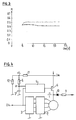
- a stepping or synchronous motor for example a two-phase unipolar motor, also called a four-phase motor in practice.
- the current flow in the motor windings is controlled by a driver circuit 2, which in turn is controlled by a control circuit 3.
- a clock frequency Clk is fed to an input of the control circuit 3.
- the clock frequency also reaches the one input of a univibrator 4, the output of which drives a switching transistor 5.
- the switching transistor 5 connects a voltage source with a highly variable operating voltage Um to the motor 1, the driver 2 determining which winding the individual current pulses are fed to.
- a resistor 6 is also connected to the voltage source, which forms a RC element with a capacitor 7, which is connected to a second input of the univibrator 4.
- a stabilized operating voltage of, for example, 5 V is supplied to this univibrator.
- the common supply line 8 to the motor can also be connected to the stabilized voltage source of, for example, 5 V via a resistor 9 and a diode
- FIG. 4 shows an embodiment which largely corresponds to that according to FIG. 1 and in which the corresponding circuit elements are identified in the same way as in FIG. 1.
- the difference is that the operating voltage Um by means of a voltage divider consisting of the resistors 11 and 12 on a lower voltage ul is reduced.
- This circuit is suitable for operating voltages which vary between 8 and 16 V, while the embodiment according to FIG. 1 is suitable for an operating voltage range of 5 to 22 V.
- the voltage divider 11, 12 is dimensioned such that the voltage ul on the RC element 6, 7 is reduced from 8 to 5 V.
- the voltage divider resistors 11, 12 are to be dimensioned such that the following condition is met: 1 1 R1 + 1 R2 ⁇ R
- the engine torque also depends on its temperature, especially the winding temperature.
- This winding temperature in turn depends on the ambient temperature, which according to the above can vary within very wide limits, for example in an automobile. It is therefore advantageous to use a resistor 6 with PTC characteristics, which means that at higher temperatures the voltage u at one input of the univibrator 4 rises less than at a lower temperature and, as a result, longer drive pulses are generated.
- FIG. 5 shows a further embodiment, in which corresponding parts are identified in the same way as in FIGS. 1 and 4.
- the operating voltage Um is converted into a digital value in an A / D converter 13, which is assigned to a microprocessor 14 is fed.
- an analog temperature signal which is generated, for example, by means of a resistor 15 with NTC or PTC characteristics, is converted into digital information and fed to the microprocessor 14.
- This microprocessor is programmed in such a way that it regulates the pulse duration on the basis of stored data as a function of the operating voltage Um and the ambient temperature in such a way that the motor torque M is practically constant.
- the microprocessor controls both the pulse duration by means of the switching transistor 5 and the phase switching by means of the driver 2.
- FIG. 6 shows a comparison between the maximum heating of the motor in the stationary operating state and the operating voltage.
- the range of the operating frequencies Clk, within which sufficient regulation takes place is somewhat limited and is, for example, 100 to 300 Hz, this range can be significantly wider in the embodiment according to FIG the microprocessor controls depending on the operating frequency.
Landscapes
- Engineering & Computer Science (AREA)
- Power Engineering (AREA)
- Control Of Stepping Motors (AREA)
Applications Claiming Priority (2)
| Application Number | Priority Date | Filing Date | Title |
|---|---|---|---|
| CH1888/90 | 1990-06-05 | ||
| CH1888/90A CH682114A5 (cg-RX-API-DMAC7.html) | 1990-06-05 | 1990-06-05 |
Publications (2)
| Publication Number | Publication Date |
|---|---|
| EP0461066A1 EP0461066A1 (de) | 1991-12-11 |
| EP0461066B1 true EP0461066B1 (de) | 1995-09-20 |
Family
ID=4220948
Family Applications (1)
| Application Number | Title | Priority Date | Filing Date |
|---|---|---|---|
| EP91810340A Expired - Lifetime EP0461066B1 (de) | 1990-06-05 | 1991-05-02 | Verfahren und Schaltung für das Steuern eines Schritt- oder Synchronmotors |
Country Status (4)
| Country | Link |
|---|---|
| EP (1) | EP0461066B1 (cg-RX-API-DMAC7.html) |
| CH (1) | CH682114A5 (cg-RX-API-DMAC7.html) |
| DE (1) | DE59106506D1 (cg-RX-API-DMAC7.html) |
| ES (1) | ES2077834T3 (cg-RX-API-DMAC7.html) |
Families Citing this family (5)
| Publication number | Priority date | Publication date | Assignee | Title |
|---|---|---|---|---|
| EP0654892A1 (de) * | 1993-11-19 | 1995-05-24 | Saia Ag | Verfahren zur Schrittmotorsteuerung |
| FR2731852B1 (fr) * | 1995-03-17 | 1997-06-06 | Valeo Electronique | Dispositif de commande d'un moteur pas a pas, notamment pour la commande d'un mecanisme dans un vehicule automobile |
| US5818193A (en) * | 1995-10-17 | 1998-10-06 | Unisia Jecs Corporation | Step motor driving method and apparatus for performing PWM control to change a step drive signal on-duty ratio |
| ITTO980028A1 (it) * | 1998-01-15 | 1999-07-15 | Plaset Srl | Sistema per il controllo di un motore elettrico brushless a semionda. |
| DE10162181A1 (de) * | 2001-12-18 | 2003-07-10 | Bosch Gmbh Robert | Verfahren und Schaltungsanordnung zum Schutz eines Elektromotors vor Überlastung |
Citations (1)
| Publication number | Priority date | Publication date | Assignee | Title |
|---|---|---|---|---|
| WO1991007009A1 (en) * | 1989-10-26 | 1991-05-16 | Siemens Aktiengesellschaft | Parametric current control for microstepping unipolar motor |
Family Cites Families (2)
| Publication number | Priority date | Publication date | Assignee | Title |
|---|---|---|---|---|
| DE3007553C2 (de) * | 1980-02-26 | 1986-08-07 | Licentia Patent-Verwaltungs-Gmbh, 6000 Frankfurt | Anordnung zur Steuerung eines fremdgesteuerten Transistorwechselrichters |
| EP0234264B1 (de) * | 1986-01-23 | 1991-04-24 | Siemens Aktiengesellschaft | Schaltungsanordnung zum Steuern eines elektrischen Schrittmotors |
-
1990
- 1990-06-05 CH CH1888/90A patent/CH682114A5/de not_active IP Right Cessation
-
1991
- 1991-05-02 ES ES91810340T patent/ES2077834T3/es not_active Expired - Lifetime
- 1991-05-02 EP EP91810340A patent/EP0461066B1/de not_active Expired - Lifetime
- 1991-05-02 DE DE59106506T patent/DE59106506D1/de not_active Expired - Fee Related
Patent Citations (1)
| Publication number | Priority date | Publication date | Assignee | Title |
|---|---|---|---|---|
| WO1991007009A1 (en) * | 1989-10-26 | 1991-05-16 | Siemens Aktiengesellschaft | Parametric current control for microstepping unipolar motor |
Also Published As
| Publication number | Publication date |
|---|---|
| CH682114A5 (cg-RX-API-DMAC7.html) | 1993-07-15 |
| ES2077834T3 (es) | 1995-12-01 |
| EP0461066A1 (de) | 1991-12-11 |
| DE59106506D1 (de) | 1995-10-26 |
Similar Documents
| Publication | Publication Date | Title |
|---|---|---|
| DE3783638T2 (de) | Motorantriebsschaltung fuer zwei drehrichtungen. | |
| DE3785059T2 (de) | Geschwindigkeitssteuerung fuer ein scheibenwischersystem. | |
| DE3211745C2 (cg-RX-API-DMAC7.html) | ||
| DE4113732C2 (de) | Lichtmaschine für Kraftfahrzeuge | |
| EP0744807B1 (de) | Verfahren zur Strombegrenzung bei einem Gleichstrommotor, und Gleichstrommotor zur Durchführung eines solchen Verfahrens | |
| DE19715688B4 (de) | Programmierbare Brennstoffeinspritzvorrichtungs-Stromwellenformsteuerung und Verfahren zum Betrieb davon | |
| DE68918232T2 (de) | Intern konfigurierbarer integrierter Mehrzweckschaltkreis zum Antreiben von externen induktiven Lasten in Schaltmodus gemäss einem auswählbaren Verbindungsschema. | |
| DE19704089C2 (de) | Verfahren zur Steuerung eines Zerhacker(Chopper)-Treibers und Schaltungsanordnung zur Durchführung des Verfahrens | |
| EP0461066B1 (de) | Verfahren und Schaltung für das Steuern eines Schritt- oder Synchronmotors | |
| DE69121488T2 (de) | Pulsbreitenmodulationsverfahren | |
| DE4119806A1 (de) | Verfahren und vorrichtung zur verminderung des leistungsverbrauches in einem wechselspannungserregten elektrolumineszenz-display | |
| DE3344662A1 (de) | Schaltungsanordnung zur ansteuerung eines magnetventils, insbesondere fuer kraftstoffeinspritzventile | |
| DE102006031402A1 (de) | Verfahren und Einrichtung zum Steuern oder Regeln eines Motors | |
| EP0462050A1 (de) | Verfahren und Schaltung zum Erfassen des Aussertrittfallens eines Schritt- oder Synchronmotors | |
| EP0811233B1 (de) | Schaltungsanordnung zur ansteuerung eines schützes | |
| DE10000020A1 (de) | Integrierte Gate-Treiberschaltung | |
| DE2633923C3 (de) | Verfahren zum Betrieb eines selbstgetakteten Schaltreglers und Vorrichtungen zur Durchführung des Verfahrens | |
| EP0583724B1 (de) | Verfahren und Schaltung zur Steuerung eines Motors | |
| DE4344355A1 (de) | Starteinrichtung für eine Brennkraftmaschine mit einem elektrischen Startermotor | |
| DE10018053A1 (de) | Schrittmotor-Stabilisierungssteuerung | |
| DE10006960A1 (de) | Spannungswandler sowie zugehöriges Arbeitsverfahren | |
| DE102005047905B4 (de) | Fahrzeugsitzanordnung mit mindestens einer elektrischen Verstellung | |
| DE3807731A1 (de) | Einrichtung zum regeln oder steuern der lage eines stellglieds, insbesondere eines stellglieds zur steuerung der innenraumtemperatur oder leuchtweite von kraftfahrzeugen | |
| EP0773624B1 (de) | Motorsteuerung für elektronisch kommutierende Gleichstrommotoren zur Kompensation von Drehmomenteinbrüchen | |
| DE4018421A1 (de) | Steuerung für einen Schrittmotor |
Legal Events
| Date | Code | Title | Description |
|---|---|---|---|
| PUAI | Public reference made under article 153(3) epc to a published international application that has entered the european phase |
Free format text: ORIGINAL CODE: 0009012 |
|
| AK | Designated contracting states |
Kind code of ref document: A1 Designated state(s): DE ES FR GB IT NL SE |
|
| 17P | Request for examination filed |
Effective date: 19911106 |
|
| 17Q | First examination report despatched |
Effective date: 19930818 |
|
| GRAA | (expected) grant |
Free format text: ORIGINAL CODE: 0009210 |
|
| ITF | It: translation for a ep patent filed | ||
| AK | Designated contracting states |
Kind code of ref document: B1 Designated state(s): DE ES FR GB IT NL SE |
|
| REF | Corresponds to: |
Ref document number: 59106506 Country of ref document: DE Date of ref document: 19951026 |
|
| REG | Reference to a national code |
Ref country code: ES Ref legal event code: FG2A Ref document number: 2077834 Country of ref document: ES Kind code of ref document: T3 |
|
| ET | Fr: translation filed | ||
| GBT | Gb: translation of ep patent filed (gb section 77(6)(a)/1977) |
Effective date: 19951116 |
|
| PLBE | No opposition filed within time limit |
Free format text: ORIGINAL CODE: 0009261 |
|
| 26N | No opposition filed | ||
| PGFP | Annual fee paid to national office [announced via postgrant information from national office to epo] |
Ref country code: SE Payment date: 19990414 Year of fee payment: 9 |
|
| PGFP | Annual fee paid to national office [announced via postgrant information from national office to epo] |
Ref country code: ES Payment date: 19990518 Year of fee payment: 9 |
|
| PGFP | Annual fee paid to national office [announced via postgrant information from national office to epo] |
Ref country code: NL Payment date: 19990531 Year of fee payment: 9 |
|
| PG25 | Lapsed in a contracting state [announced via postgrant information from national office to epo] |
Ref country code: SE Free format text: LAPSE BECAUSE OF NON-PAYMENT OF DUE FEES Effective date: 20000503 Ref country code: ES Free format text: THE PATENT HAS BEEN ANNULLED BY A DECISION OF A NATIONAL AUTHORITY Effective date: 20000503 |
|
| PG25 | Lapsed in a contracting state [announced via postgrant information from national office to epo] |
Ref country code: NL Free format text: LAPSE BECAUSE OF NON-PAYMENT OF DUE FEES Effective date: 20001201 |
|
| EUG | Se: european patent has lapsed |
Ref document number: 91810340.9 |
|
| NLV4 | Nl: lapsed or anulled due to non-payment of the annual fee |
Effective date: 20001201 |
|
| REG | Reference to a national code |
Ref country code: GB Ref legal event code: IF02 |
|
| REG | Reference to a national code |
Ref country code: ES Ref legal event code: FD2A Effective date: 20020204 |
|
| PGFP | Annual fee paid to national office [announced via postgrant information from national office to epo] |
Ref country code: GB Payment date: 20040426 Year of fee payment: 14 |
|
| PGFP | Annual fee paid to national office [announced via postgrant information from national office to epo] |
Ref country code: FR Payment date: 20040428 Year of fee payment: 14 |
|
| PGFP | Annual fee paid to national office [announced via postgrant information from national office to epo] |
Ref country code: DE Payment date: 20040528 Year of fee payment: 14 |
|
| PG25 | Lapsed in a contracting state [announced via postgrant information from national office to epo] |
Ref country code: IT Free format text: LAPSE BECAUSE OF NON-PAYMENT OF DUE FEES;WARNING: LAPSES OF ITALIAN PATENTS WITH EFFECTIVE DATE BEFORE 2007 MAY HAVE OCCURRED AT ANY TIME BEFORE 2007. THE CORRECT EFFECTIVE DATE MAY BE DIFFERENT FROM THE ONE RECORDED. Effective date: 20050502 Ref country code: GB Free format text: LAPSE BECAUSE OF NON-PAYMENT OF DUE FEES Effective date: 20050502 |
|
| PG25 | Lapsed in a contracting state [announced via postgrant information from national office to epo] |
Ref country code: DE Free format text: LAPSE BECAUSE OF NON-PAYMENT OF DUE FEES Effective date: 20051201 |
|
| GBPC | Gb: european patent ceased through non-payment of renewal fee |
Effective date: 20050502 |
|
| PG25 | Lapsed in a contracting state [announced via postgrant information from national office to epo] |
Ref country code: FR Free format text: LAPSE BECAUSE OF NON-PAYMENT OF DUE FEES Effective date: 20060131 |
|
| REG | Reference to a national code |
Ref country code: FR Ref legal event code: ST Effective date: 20060131 |