EP0460659B1 - Facsimile apparatus - Google Patents
Facsimile apparatus Download PDFInfo
- Publication number
- EP0460659B1 EP0460659B1 EP91109272A EP91109272A EP0460659B1 EP 0460659 B1 EP0460659 B1 EP 0460659B1 EP 91109272 A EP91109272 A EP 91109272A EP 91109272 A EP91109272 A EP 91109272A EP 0460659 B1 EP0460659 B1 EP 0460659B1
- Authority
- EP
- European Patent Office
- Prior art keywords
- circuit substrate
- bottom cover
- apparatus body
- control circuit
- section
- Prior art date
- Legal status (The legal status is an assumption and is not a legal conclusion. Google has not performed a legal analysis and makes no representation as to the accuracy of the status listed.)
- Expired - Lifetime
Links
Images


Classifications
-
- G—PHYSICS
- G03—PHOTOGRAPHY; CINEMATOGRAPHY; ANALOGOUS TECHNIQUES USING WAVES OTHER THAN OPTICAL WAVES; ELECTROGRAPHY; HOLOGRAPHY
- G03G—ELECTROGRAPHY; ELECTROPHOTOGRAPHY; MAGNETOGRAPHY
- G03G15/00—Apparatus for electrographic processes using a charge pattern
- G03G15/80—Details relating to power supplies, circuits boards, electrical connections
-
- G—PHYSICS
- G03—PHOTOGRAPHY; CINEMATOGRAPHY; ANALOGOUS TECHNIQUES USING WAVES OTHER THAN OPTICAL WAVES; ELECTROGRAPHY; HOLOGRAPHY
- G03G—ELECTROGRAPHY; ELECTROPHOTOGRAPHY; MAGNETOGRAPHY
- G03G21/00—Arrangements not provided for by groups G03G13/00 - G03G19/00, e.g. cleaning, elimination of residual charge
- G03G21/16—Mechanical means for facilitating the maintenance of the apparatus, e.g. modular arrangements
- G03G21/1604—Arrangement or disposition of the entire apparatus
- G03G21/1623—Means to access the interior of the apparatus
-
- G—PHYSICS
- G03—PHOTOGRAPHY; CINEMATOGRAPHY; ANALOGOUS TECHNIQUES USING WAVES OTHER THAN OPTICAL WAVES; ELECTROGRAPHY; HOLOGRAPHY
- G03G—ELECTROGRAPHY; ELECTROPHOTOGRAPHY; MAGNETOGRAPHY
- G03G21/00—Arrangements not provided for by groups G03G13/00 - G03G19/00, e.g. cleaning, elimination of residual charge
- G03G21/16—Mechanical means for facilitating the maintenance of the apparatus, e.g. modular arrangements
- G03G21/1642—Mechanical means for facilitating the maintenance of the apparatus, e.g. modular arrangements for connecting the different parts of the apparatus
- G03G21/1652—Electrical connection means
-
- H—ELECTRICITY
- H04—ELECTRIC COMMUNICATION TECHNIQUE
- H04N—PICTORIAL COMMUNICATION, e.g. TELEVISION
- H04N1/00—Scanning, transmission or reproduction of documents or the like, e.g. facsimile transmission; Details thereof
- H04N1/00519—Constructional details not otherwise provided for, e.g. housings, covers
- H04N1/00543—Allowing easy access, e.g. for maintenance or in case of paper jam
- H04N1/00546—Allowing easy access, e.g. for maintenance or in case of paper jam using a side opening
-
- G—PHYSICS
- G03—PHOTOGRAPHY; CINEMATOGRAPHY; ANALOGOUS TECHNIQUES USING WAVES OTHER THAN OPTICAL WAVES; ELECTROGRAPHY; HOLOGRAPHY
- G03G—ELECTROGRAPHY; ELECTROPHOTOGRAPHY; MAGNETOGRAPHY
- G03G2221/00—Processes not provided for by group G03G2215/00, e.g. cleaning or residual charge elimination
- G03G2221/16—Mechanical means for facilitating the maintenance of the apparatus, e.g. modular arrangements and complete machine concepts
- G03G2221/1651—Mechanical means for facilitating the maintenance of the apparatus, e.g. modular arrangements and complete machine concepts for connecting the different parts
- G03G2221/1654—Locks and means for positioning or alignment
-
- G—PHYSICS
- G03—PHOTOGRAPHY; CINEMATOGRAPHY; ANALOGOUS TECHNIQUES USING WAVES OTHER THAN OPTICAL WAVES; ELECTROGRAPHY; HOLOGRAPHY
- G03G—ELECTROGRAPHY; ELECTROPHOTOGRAPHY; MAGNETOGRAPHY
- G03G2221/00—Processes not provided for by group G03G2215/00, e.g. cleaning or residual charge elimination
- G03G2221/16—Mechanical means for facilitating the maintenance of the apparatus, e.g. modular arrangements and complete machine concepts
- G03G2221/1651—Mechanical means for facilitating the maintenance of the apparatus, e.g. modular arrangements and complete machine concepts for connecting the different parts
- G03G2221/166—Electrical connectors
-
- G—PHYSICS
- G03—PHOTOGRAPHY; CINEMATOGRAPHY; ANALOGOUS TECHNIQUES USING WAVES OTHER THAN OPTICAL WAVES; ELECTROGRAPHY; HOLOGRAPHY
- G03G—ELECTROGRAPHY; ELECTROPHOTOGRAPHY; MAGNETOGRAPHY
- G03G2221/00—Processes not provided for by group G03G2215/00, e.g. cleaning or residual charge elimination
- G03G2221/16—Mechanical means for facilitating the maintenance of the apparatus, e.g. modular arrangements and complete machine concepts
- G03G2221/1672—Paper handling
-
- G—PHYSICS
- G03—PHOTOGRAPHY; CINEMATOGRAPHY; ANALOGOUS TECHNIQUES USING WAVES OTHER THAN OPTICAL WAVES; ELECTROGRAPHY; HOLOGRAPHY
- G03G—ELECTROGRAPHY; ELECTROPHOTOGRAPHY; MAGNETOGRAPHY
- G03G2221/00—Processes not provided for by group G03G2215/00, e.g. cleaning or residual charge elimination
- G03G2221/16—Mechanical means for facilitating the maintenance of the apparatus, e.g. modular arrangements and complete machine concepts
- G03G2221/1678—Frame structures
- G03G2221/169—Structural door designs
Definitions
- the present invention relates to a facsimile apparatus adapted to cope with different specifications in various countries.
- US 4,768,100 shows an image processing apparatus in which the respective functional sections in the apparatus are clearly separated and constituted as units, thereby raising the productivity, and at the same time the maintenance for the reading optical system and for the jam processing of the sheets and the like can be easily performed.
- the enclosing space for the recording sheets discharged is built inside the casing, and the original base is also used as the cover for the recording system unit, thereby realizing a small and thin sized apparatus.
- a further facsimile equipment which comprises a cover holding a board is known. This cover is opened/closed by removing a screw and turning the cover around a turning shaft for the maintenance of the board.
- the conventional facsimile apparatus has a construction in which a plurality of molded top covers 32 and bottom covers 33 are mounted on a molded body frame 31 as shown in Fig. 9.
- a control circuit substrate 34 (including a system control unit and a network control unit) is first attached onto the bottom cover 33, and then there is arranged the body frame 31 on which units and electronic components are assembled so as to drop-in.
- an input/output terminal 35 for circuits or the like is fixed to the far side (left side in the figure) of the bottom cover 33.
- the upper cover 32 and the like are mounted to complete the assembling.
- the first circuit substrate unit is electrically connected with the second circuit substrate through an aperture provided on the body frame.
- a first connector 42a located at one end of a connection cord 42 is previously coupled with a power supply connector 41a of a power supply substrate 411, a second connector 42b located at another end of the connection cord 42 is passed through an aperture 43 from the left side, and then the power supply unit 41 is fitted into a receiving portion provided at the end of the apparatus body. And finally the second connector 42b of the connection cord 42 is linked with a control connector 34a of the control circuit substrate 34.
- each unit is automatically assembled by a drop-in method
- the automatic assembling work has to be interrupted temporarily to perform a manual working. After that, the automatic assembling work is restarted, which leads to the increase in the number of working processes, resulting in an extremely insufficient and time-consuming assembling steps, to consequently bring about a raise in production costs.
- a roll paper receiving section 40 which has hook apertures 40a, 40b for catches of a partition which differs according to the sheet width such as A4 and B4. It is therefore feared that through these apertures 40a, 40b foreign matters such as clicks and pins may fall to cause a short circuit.
- a net can be put up over the control circuit substrate 34 to prevent the foreign matters from falling onto the control circuit substrate 34.
- the facsimile apparatus there are needs to correct the assembling defect and to check the control circuit substrate 34 to perform the maintenance in the market.
- the conventional facsimile apparatus requires an extremely time-consuming work in which after the removal of the upper cover 32, the body frame 31 loaded with the units or electronic components has to be raised so as to turn in the direction of R around a shaft 36 to execute the checking operation of the control circuit substrate 34.
- the once assembled apparatus has to be disassembled and then reassembled.
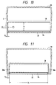
- the bottom portion of some facsimile apparatus serves as a bottom cover 37 capable of opening and closing as shown in Fig. 10.
- the body and the side wall are integrally molded as the body frame 38, and then sheathed with the bottom cover 37 and upper cover 39.
- the control circuit substrate 34 of which dimensions are extremely restricted, which results from the fact the lower end of the body frame 38 is of a very thin section due to the draft angle, leading to the difficulties of molding.
- providing the height h above the substrate 34 is required to be 30 to 40 mm, an end x2 of the body frame 38 becomes extremely thin to be liable to cause a defective molding.
- the draft angles of at least 3 degrees for the external surface S and at least 1 degree for the inner wall T must be provided due to the graining or other processing.
- the apparatus body having such structure has not been manufactured in practice, but instead a constitution as shown in Fig. 11 is employed.
- This facsimile apparatus has at its bottom portion a baggy portion 38a to overcome the above disadvantages. Because of not only doubling the thickness of the end but also need of the thickness x3 for a core die, the substrate space x4 is smaller for the size of the apparatus.
- a second object of the present invention is to provide a facsimile apparatus which is enough firm and easy to assemble.
- a third object of the present invention is to provide a facsimile apparatus in which foreign matters are prevented from falling onto the control circuit substrate through apertures provided on the recording roll paper receiving portion.
- a fifth object of the present invention is to provide a facsimile apparatus in which circuit substrate units are connected with each other without difficulty to ensure the effective assembling.
- Fig. 1 is a structural drawing of the facsimile apparatus in accordance with an embodiment of the present invention.
- Fig. 2 shows the facsimile apparatus in Fig. 1 with a bottom cover opened.
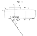
- Fig. 3 is a side view of the apparatus shown in Fig. 1.
- Fig. 4 is a sectional view taken along a line O-O in Fig. 3.
- Fig. 5 is a sectional view taken along a line P-P in Fig. 3.
- Fig. 6 is a perspective view of the bottom cover in Fig. 1.
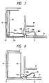
- Fig. 7 shows a variant of the electric connection between a power supply unit and a control circuit substrate as shown in Fig. 1.
- Fig. 8 shows another variant of the electrical connection between the power supply unit and the control circuit substrate.
- Fig. 9 is a structural drawing of the conventional facsimile apparatus.
- Fig. 10 is a schematic diagram of the facsimile apparatus in Fig. 7 in which the bottom cover is releasable.
- Fig. 11 is also a schematic diagram but of the conventional facsimile apparatus which strengthens the apparatus in Fig. 10.
- Fig. 1 shows the overall structure of the apparatus, where reference numeral 1 denotes an original, 2 a document conveying section which forms at its lower portion an assembling unit as shown by a broken line.
- Reference numeral 3 represents an optical reading section which forms a unit at the time of assembling as shown by a broken line
- reference numeral 4 denotes a thermosensible recording paper
- 5 a printing section
- 6 a record paper cutting portion which forms a unit when assembled as shown by a broken line.
- Reference numeral 7 denotes an ejected paper stack, 8 a record paper curling elimination section, and 9 an operation panel which forms a unit as shown by a broken line in cooperation with the upper portion of the document conveying section 2 when assembled.
- Reference numeral 10 denotes a body frame, 11 a bottom cover which is fitted to the body frame 10 by means of screws 11a, 11b, reference numeral 12 represents an upper cover, and 13 a recording cover which forms a unit as shown by a broken line in cooperation with the printing section 5 when assembled.
- Reference numeral 14 denotes a control circuit substrate which is separated by the body frame 10 from the other units and the electronic components and arranged in the bottom portion of the apparatus body. In order to repair the control circuit substrate 14 attached to the bottom cover 11, the bottom cover 11 can be opened as shown in Fig. 2 by removing the screws 11a and 11b.
- Reference numeral 15 is a power supply unit
- 16a and 16b denote a connection cord, and 17 an aperture provided on the body frame 10, through which the power supply unit 15 is connected to the control circuit substrate 14 with the aid of the connection cord 16a, and through which the printing section 5 is also connected to the power supply unit 15 with the aid of the connection cord 16b.
- Reference numeral 18 denotes a ejected paper receiving tray and 19 a speaker fixed to the bottom cover 11.
- the speaker 19 is located at a lower portion between a roll paper receiving section 27 and the printing section 5. This portion is a dead space of the apparatus which is formed by the body frame 10 so as to make effective use of the dead space.
- the bottom cover 11 is extended up to the position, and on the extension of the bottom cover there are provided large-sized electric components such as the speaker 19.
- Reference numeral 20 signifies a shield plate.
- Reference numeral 27 designates the roll paper receiving section having therein a partition plate 28 which differs depending on the paper width, and having hook apertures 27a, 27b for catches 28a, 28b of the partition plate 28.
- the bottom cover 11 is extended up to the position below the roll paper receiving section 27, the inner surface of the bottom cover is brought into contact with the ribs 27c, 27d when the bottom cover is closed. This causes the hook apertures 27a, 27b of the roll paper receiving section 27 to be separated from the control circuit substrate 14, thus preventing the foreign matters such as air dust from adhering to the control circuit substrate 34 through the hook apertures 27a, 27b.
- a power supply circuit 151 having various components, and perpendicular to which there is provided a support substrate 152 to one end of which there is attached a first connector 26a.
- the substrates 151 and 152 are electrically connected by means of connectors 15a, 15b.
- the first connector 26a facing the aperture 17 is connected to the output circuit of the power supply substrate 151 through the wiring pattern of the support substrate 152.
- 153 denotes a power supply frame serving as a chassis and a cooling fin.
- the connection cord 16a has one end connecting to the input circuit of the control circuit substrate 14 and the other end connecting to the second connector 26b which is connected with the first connector 26a of the power supply unit 15 through the aperture 17.
- Figs. 2 and 3 are lateral views of the apparatus shown in Fig. 1, in which reference numeral 22 denotes side walls which are molded separately from the body frame 10.
- the side walls 22 have their both sides notches or cut-away portions 22a, 22b respectively for receiving the modular covers 23, 24 which are fixed to the substrate 14 with screws 23a and 24a.
- Modular terminals 21a to 21d in the cover 23 are soldered to the substrate 14.
- 21A is a line input of a general telecommunication circuit network
- 21b is a telephone line to a hand set attached to the facsimile
- 21c is a sub-telephone terminal for connecting a sub-telephone apart from the facsimile body.
- a modular terminal 24d in the cover 24 is also soldered to the substrate 14 as shown in Fig. 4.
- the side walls 22 are planar except the notches 22a, 22b for covers 23, 24 as shown in Figs. 4 and 5.
- the notches 22a and 22b have at their upper portions grooves 22 1a , 22 1b so as to engage with the body frame 10 as well as grooves 22 2a , 22 2b which are engaged with protrusions 23b, 24b of the covers 23, 24.
- Such side walls 22 are fixed to the body frame 10 with screws 223, 224.
- the bottom cover 11 is configured as shown in Fig. 6 in which 25 denotes a memory back-up battery of the apparatus, 25a is a signal line, and 19a is a signal line for the speaker 19.
- the side walls 22 are separately provided from the body frame 10, the space for the substrate 14 secured to the bottom cover 11 is defined by the side walls 22, and the bottom cover 11 is attached to the body frame 10, so as to maximize the space for mounting the substrate 14 and ensure the secure attachment of the bottom cover 11.
- the side walls 22 are provided with the notches 22a, 22b which receive the modular covers 23, 24 equipped with the modular terminals 21a to 21d, and the modular covers 23, 24 along with the modular terminals 21a to 21d are in turn attached to the substrate 14, thereby decreasing the number of the signal lines and holding the conversion components for the change of destination together with the bottom cover 11 as one unit.
- the surroundings of the notches 22a and 22b are strengthened by virtue of the modular covers 23, 24, side walls 22, and the body frame 10, thereby fully compensating the strength reduction caused by the formation of the notches 22a, 22b.
- originals 1 stacked on the upper surface of the recording cover 13 are separated one by one with the aid of a preliminary conveying roller 2c in pressure-contact with a separation press piece 2a, and a separation roller 2d in pressure-contact with the separation friction piece 2b, conveyed by a paper feed roller 2g in pressure-contact with a press roller 2e, and a paper ejection roller 2h in pressure-contact with a press roller 2f, to finally stack up on the paper receiving tray 18.
- Reference numeral 2i means an upper original support, and 2j a lower original support.
- the bottom surface of the original 1 further conveyed is illuminated by a light source 3b such as an LED array through a document glass 3a, the reflected light ray is led to a photoelectric conversion element 3g such as CCD by mirrors 3c, 3d, 3e through a lens 3f, and the obtained image is recorded by its own recording section 5 in copy mode, and transmitted to the recording portion of the other apparatus in facsimile mode (transmission mode).
- a light source 3b such as an LED array through a document glass 3a
- the reflected light ray is led to a photoelectric conversion element 3g such as CCD by mirrors 3c, 3d, 3e through a lens 3f
- the obtained image is recorded by its own recording section 5 in copy mode, and transmitted to the recording portion of the other apparatus in facsimile mode (transmission mode).
- thermosensible recording paper 4 in the form of roll paper is dropped in the roll receiving section of the frame 10.
- Reference numeral 4a shows a roll-full state
- 4b shows a roll-empty state.
- the roll paper 4 is deprived of its curl by means of a curl eliminating section 8, and then conveyed in the direction of paper ejection by a platen roller 5a which is driven by a motor not shown.
- one-dot printing is carried out on the recording paper 4 through a heat-sensitive head (thermal head) 5b which is in pressure-contact with a platen roller 5a.
- the printed recording paper is passed between a fixed blade 6a and a rotationally shifting blade 6b of the cutter section, into a reverse tray section composed of an inner tray 7a and an outer tray 7b with its leading edge ahead.
- the recording paper successively fed by the platen roller is ejected to the outside of the apparatus turning in a loop with its leading edge inserted into the reverse tray section, to be ejected to the outside of the apparatus describing the loop shape.
- the shifting blade 6b is rotated upward in the figure to cut the paper, the trailing edge is ejected to the outside of the apparatus with the leading edge clamped.
- reference numeral 8a represents a shiftable guide shaft, 8b a fixed shaft (which is fixed on the recording cover 13 side) and 8c a rotation axis of the guide shaft 8a.
- the shiftable guide shaft 8a is positioned according to the remaining roll diameter of the roll paper 4, that is, it is shifted to a position 8a in the figure by a mechanism not shown when the roll paper is small just as the core diameter, while to a position 8d in the figure when the roll paper is almost full, thereby change the amount of the roll paper rolled up onto the fixed shaft 8b.
- the degree of the curl elimination is altered, to constantly confer a uniform flatness to the ejected roll paper.
- reference numeral 9 signifies an operation panel section, 9a a display such as a liquid crystal display LCD, 9d an operation panel control substrate OPCNT (operation control substrate), 9c a keytop, 9d a tact switch on the OPCNT.
- a display such as a liquid crystal display LCD
- OPCNT operation control substrate
- 9c keytop
- 9d a tact switch on the OPCNT.
- the injection-molded body frame 10 is attached to the side walls 22.
- the end of the body frame 10 is fitted into grooves 22 1a , 22 1b of the side walls 22, and then the body frame 10 is secured to the side walls 22 with screws 223, 224.
- each unit is dropped into the body frame 10 by means of the automatic assembling machine to perform the assembling work. That is, first a unit equipped with the recording paper cutting section 6, and next a unit with the optical reading section 3 are mounted to the body frame 10, and then the power supply unit 15 is fitted into the receiving section of the body frame 10.
- the first connector 26a which is connected to the output circuit of the power supply substrate 151 through a wiring pattern of the support substrate 152 is disposed facing the body frame 10, thereby facilitating the connection of the second connector 26b to the first connector 26a through the aperture 17.
- a unit provided with the recording cover 13 and the printing section 5 is mounted to the body frame 10.
- a unit with the lower portion of the document conveying section 2 is mounted to the body frame 10.
- the bottom cover 11 equipped with a control circuit substrate 14 and the speaker 19 is to be mounted to the body frame 10.
- the catches located at the end of the bottom cover 11 are hooked into the grooves of the body frame 10, and then the protruding pieces 23b, 24b of the modular covers 23, 24 are fitted in the groove portions 22 2a , 22 2b of the side walls 22, and the bottom cover 11 is fastened to the body frame 10 with screws 11a, 11b.
- the inner surface of the bottom cover 11 is abutted with the ribs 27c, 27d, and thereby the hook apertures 27a, 27b of the roll paper receiving section 27 are separated from the control circuit substrate 14, thus preventing an entry of air dust through the hook apertures 27a, 27b into the control circuit substrate 34.
- the second connector 26b of the connection cord 16a which is linked with the input circuit of the control circuit substrate 14 has only to be connected to the first connector 26a of the power supply unit 15 through the aperture 17 of the body frame 10.
- connection cord 16b the electrical connection between the power supply unit 15 and the unit having the printing section 5 is carried out in the same manner by means of the connection cord 16b through the aperture 17.
- connection cord 16b the electrical connection between the control circuit substrate 14 and the power supply unit 15, and other unit are also carried out by the connection cord through an aperture not shown of the body frame 10.
- the modular covers 23, 24 are screwed to the substrates 14, but instead they may be fixed to the bottom cover 11.
- the similar effects can be also obtained by a temporary locking such as hooking by use of catches in place of screwing since the modular covers are clamped between the substrate 14 and the cover 11 at the time of assembling.
- a sub-substrate loaded with connectors and serving as a support substrate is placed within the power supply.
- the connector 26a may be fixed to the frame 153 of the power supply unit 15 with machine screws, and linked with the main substrate 151 through a lead wire 26 a1 as shown in Fig. 7.
- a right-angle type connector 26a may be provided by notching the lower portion of the substrate 151, thus allowing the connector to be inserted from the lower portion of the control circuit substrate 14 by mounting the power supply output connector onto the reverse side of the substrate 151.
- the description of the above embodiment is made with regard to the structure where the power supply is not overlaid on the control circuit substrate 14 when perspectively viewed from the above of the apparatus body.
- the position of the power supply in Fig. 1 may be shifted upward to place the control circuit substrate on the far side in the lower portion of the power supply, whereby the control circuit substrate connector can be inserted upwardly from the below through the aperture of the bottom cover or the frame which is positioned below the power supply on the control circuit substrate, thus obtaining the similar effects.
- the roll paper receiving section of the body frame is slightly tilted toward the front side of the apparatus, which aims at an effect that when the diameter of the roll paper has become small, the roll paper can rest on the front side of the apparatus due to the gravity.
- the surface may be flat, or the roll paper receiving section may be brought into intimate-contact with the bottom cover.
- the ribs are formed on the body frame side, instead the ribs and spot members may be provided on the bottom cover.
- an apparatus of a type laterally disposing the apparatus of the above embodiment may be used to obtain the similar effects.
- a foamed moltplane rubber may be stuck, or the both may be executed at the same time to heighten the sealing properties.
- the above embodiment is provided with a speaker, a battery and the like as large-sized electric components, which are not exclusive.
- a speaker, a battery and the like as large-sized electric components, which are not exclusive.
- the use of any components capable of being directly connected to the control circuit substrates for a noise filter, a core, an illumination lighting inverter, and a driver circuit for motors leads to the same effect that a wire bundling is unnecessary at the time of mounting.
- the control circuit substrate is arranged in the bottom portion of the apparatus body, the bottom cover capable of opening and closing the bottom portion of the apparatus body serves as a support member for the control circuit substrate, the input/output terminals for lines to be connected to the control circuit substrate are positioned at the side of the apparatus body, and the retaining frames for the input/output terminals are integrally formed with the bottom cover so as to constitute a part of the side wall of the apparatus body.
- the side walls are formed individually as members separate from the apparatus body, and include an upwardly extending groove which is engaged with the end of the body frame and a downwardly extending grooves which there are provided an upward extending groove which is engaged with the bottom cover, thereby fitting the side walls and the bottom cover to the body frame. Accordingly, the apparatus body can be formed by merely dropping-in from the above and screwing, thus ensuring the easy assembling of the apparatus.
- the bottom cover is so formed as to extend up to the position of the recording roll paper receiving section in the recording section, and through the cooperation of the bottom cover and the recording roll paper receiving section, there is formed a section for preventing the foreign matter to invade through the aperture of the recording roll paper receiving section into control circuit substrate, thereby preventing the entry of the foreign matter through the aperture of the roll paper receiving section and the resultant trouble such as a short of the electric circuit of the circuit substrate, to consequently improve the safety.
- a large-sized components such as the speaker and the battery to be directly connected to the control circuit substrate can be arranged in the space between the roll paper and the platen roller, and the cables and the like can be fixed inside the unit, thus resulting in the reduction in the height of the circuit substrate itself which allows the height of the entire apparatus to be lowered, and leading to the reduction in the numbers of assembling steps owing to the easy maintenance, to consequently realize the low-cost apparatus.
- the first connector to be linked with the first circuit substrate unit is fastened to the support member extending from the first circuit substrate unit, while the first connector attached to the support member is so arranged as to confront the aperture of the body frame when the first circuit substrate unit is loaded into the apparatus body, and the second connector to be connected to the second circuit substrate unit is allowed to couple with the first connector through the aperture of the body frame.
- a control circuit substrate is arranged on the bottom portion of the apparatus body, a bottom cover capable of opening and closing the bottom portion of the apparatus serves as a support member, input/output terminals for lines to be connected to the control circuit substrate are positioned at the side of the apparatus body, and retaining frames for the input/output terminals are intergrally formed with the bottom cover so as to constitute a part of the side wall of the apparatus body.
Description
- The present invention relates to a facsimile apparatus adapted to cope with different specifications in various countries.
- US 4,768,100 shows an image processing apparatus in which the respective functional sections in the apparatus are clearly separated and constituted as units, thereby raising the productivity, and at the same time the maintenance for the reading optical system and for the jam processing of the sheets and the like can be easily performed. The enclosing space for the recording sheets discharged is built inside the casing, and the original base is also used as the cover for the recording system unit, thereby realizing a small and thin sized apparatus.
- From JP 62-45264, a further facsimile equipment which comprises a cover holding a board is known. This cover is opened/closed by removing a screw and turning the cover around a turning shaft for the maintenance of the board.
- With the rapid spread of facsimiles all over the world in recent years, it is required to be easily cope with different power supplies such as 100V, 120V, and 230V and different public lines in various countries. Moreover, it is also desired that parts be easily molded and fabricated in any place as they are locally manufactured all over the world. Further, a facsimile structure easy to perform the maintenance work is also needed.
- The conventional facsimile apparatus has a construction in which a plurality of molded
top covers 32 andbottom covers 33 are mounted on a moldedbody frame 31 as shown in Fig. 9. In order to assemble such facsimile, a control circuit substrate 34 (including a system control unit and a network control unit) is first attached onto thebottom cover 33, and then there is arranged thebody frame 31 on which units and electronic components are assembled so as to drop-in. In the course of this assembling, an input/output terminal 35 for circuits or the like is fixed to the far side (left side in the figure) of thebottom cover 33. Finally, theupper cover 32 and the like are mounted to complete the assembling. - Due to this, there is a case where two different circuit substrate units, that is, a first and a second circuit substrate units are separated by the body frame. Under such condition, the first circuit substrate unit is electrically connected with the second circuit substrate through an aperture provided on the body frame.
- For example, to electrically connect a power supply unit 41 with the
control circuit substrate 34 during assembly, afirst connector 42a located at one end of aconnection cord 42 is previously coupled with apower supply connector 41a of apower supply substrate 41₁, asecond connector 42b located at another end of theconnection cord 42 is passed through anaperture 43 from the left side, and then the power supply unit 41 is fitted into a receiving portion provided at the end of the apparatus body. And finally thesecond connector 42b of theconnection cord 42 is linked with acontrol connector 34a of thecontrol circuit substrate 34. - The operations for previously coupling the
first connector 42a of theconnection cord 42 with thepower supply connector 41a and for inserting thesecond connector 42b of theconnection cord 42 into the aperture are difficult to carry out by an automatic machine, and hence it is to be manually performed. - Accordingly, in the case where each unit is automatically assembled by a drop-in method, during the assembly of the power supply unit 41, the automatic assembling work has to be interrupted temporarily to perform a manual working. After that, the automatic assembling work is restarted, which leads to the increase in the number of working processes, resulting in an extremely insufficient and time-consuming assembling steps, to consequently bring about a raise in production costs.
- This problem likely arises not only in the case of the electrical connection between the power supply unit 41 and the
control circuit substrate 34, but also in the case of an electrical connection between two circuit substrate units which are separated by the body frame such as the connection between the control circuit substrate and other circuit substrate. - Further, on the
body frame 31, there is provided a rollpaper receiving section 40 which hashook apertures apertures control circuit substrate 34 to prevent the foreign matters from falling onto thecontrol circuit substrate 34. - Moreover, as to the facsimile apparatus, there are needs to correct the assembling defect and to check the
control circuit substrate 34 to perform the maintenance in the market. In this case, the conventional facsimile apparatus requires an extremely time-consuming work in which after the removal of theupper cover 32, thebody frame 31 loaded with the units or electronic components has to be raised so as to turn in the direction of R around ashaft 36 to execute the checking operation of thecontrol circuit substrate 34. In addition, in case of the change in specifications, the once assembled apparatus has to be disassembled and then reassembled. - In order to solve such inconveniences, of late the bottom portion of some facsimile apparatus serves as a
bottom cover 37 capable of opening and closing as shown in Fig. 10. - In such apparatus, the body and the side wall are integrally molded as the
body frame 38, and then sheathed with thebottom cover 37 andupper cover 39. To this bottom cover, there is provided thecontrol circuit substrate 34 of which dimensions are extremely restricted, which results from the fact the lower end of thebody frame 38 is of a very thin section due to the draft angle, leading to the difficulties of molding. In other words, providing the height h above thesubstrate 34 is required to be 30 to 40 mm, an end x₂ of thebody frame 38 becomes extremely thin to be liable to cause a defective molding. The reason is that in view of the mold structure the draft angles of at least 3 degrees for the external surface S and at least 1 degree for the inner wall T must be provided due to the graining or other processing. On the contrary, unless the section of thebody frame 38 is uniform, there arise sunk spots and welds, and hence it is impossible for the thickness x₁ to be larger than 3 to 4 mm, which leads to a smaller x₂. Accordingly, the apparatus body having such structure has not been manufactured in practice, but instead a constitution as shown in Fig. 11 is employed. This facsimile apparatus has at its bottom portion abaggy portion 38a to overcome the above disadvantages. Because of not only doubling the thickness of the end but also need of the thickness x₃ for a core die, the substrate space x₄ is smaller for the size of the apparatus. - In consequence, when a speaker or other large-sized electric components are arranged on such facsimile apparatus, the apparatus body becomes even larger.
- It is a primary object of the present invention to solve the above disadvantages and to provide a facsimile apparatus which is easy to change the destinations and to perform the maintenance.
- A second object of the present invention is to provide a facsimile apparatus which is enough firm and easy to assemble.
- A third object of the present invention is to provide a facsimile apparatus in which foreign matters are prevented from falling onto the control circuit substrate through apertures provided on the recording roll paper receiving portion.
- It is a fourth object of the present invention to solve the above disadvantages and to provide a facsimile apparatus in which large-sized electric components are arranged in a dead space of the apparatus.
- A fifth object of the present invention is to provide a facsimile apparatus in which circuit substrate units are connected with each other without difficulty to ensure the effective assembling.
- This objects are achieved by the apparatus according to
claim 1. - The invention is further developed by the features mentioned in the subclaims.
- Fig. 1 is a structural drawing of the facsimile apparatus in accordance with an embodiment of the present invention.
- Fig. 2 shows the facsimile apparatus in Fig. 1 with a bottom cover opened.
- Fig. 3 is a side view of the apparatus shown in Fig. 1.
- Fig. 4 is a sectional view taken along a line O-O in Fig. 3.
- Fig. 5 is a sectional view taken along a line P-P in Fig. 3.
- Fig. 6 is a perspective view of the bottom cover in Fig. 1.
- Fig. 7 shows a variant of the electric connection between a power supply unit and a control circuit substrate as shown in Fig. 1.
- Fig. 8 shows another variant of the electrical connection between the power supply unit and the control circuit substrate.
- Fig. 9 is a structural drawing of the conventional facsimile apparatus.
- Fig. 10 is a schematic diagram of the facsimile apparatus in Fig. 7 in which the bottom cover is releasable.
- Fig. 11 is also a schematic diagram but of the conventional facsimile apparatus which strengthens the apparatus in Fig. 10.
- An embodiment of the present invention will be described hereinafter with reference to the accompanying drawings.
- Fig. 1 shows the overall structure of the apparatus, where
reference numeral 1 denotes an original, 2 a document conveying section which forms at its lower portion an assembling unit as shown by a broken line.Reference numeral 3 represents an optical reading section which forms a unit at the time of assembling as shown by a broken line,reference numeral 4 denotes a thermosensible recording paper, 5 a printing section, and 6 a record paper cutting portion which forms a unit when assembled as shown by a broken line.Reference numeral 7 denotes an ejected paper stack, 8 a record paper curling elimination section, and 9 an operation panel which forms a unit as shown by a broken line in cooperation with the upper portion of thedocument conveying section 2 when assembled.Reference numeral 10 denotes a body frame, 11 a bottom cover which is fitted to thebody frame 10 by means ofscrews reference numeral 12 represents an upper cover, and 13 a recording cover which forms a unit as shown by a broken line in cooperation with theprinting section 5 when assembled.Reference numeral 14 denotes a control circuit substrate which is separated by thebody frame 10 from the other units and the electronic components and arranged in the bottom portion of the apparatus body. In order to repair thecontrol circuit substrate 14 attached to thebottom cover 11, thebottom cover 11 can be opened as shown in Fig. 2 by removing thescrews Reference numeral 15 is a power supply unit, 16a and 16b denote a connection cord, and 17 an aperture provided on thebody frame 10, through which thepower supply unit 15 is connected to thecontrol circuit substrate 14 with the aid of theconnection cord 16a, and through which theprinting section 5 is also connected to thepower supply unit 15 with the aid of theconnection cord 16b.Reference numeral 18 denotes a ejected paper receiving tray and 19 a speaker fixed to thebottom cover 11. Thespeaker 19 is located at a lower portion between a rollpaper receiving section 27 and theprinting section 5. This portion is a dead space of the apparatus which is formed by thebody frame 10 so as to make effective use of the dead space. Thebottom cover 11 is extended up to the position, and on the extension of the bottom cover there are provided large-sized electric components such as thespeaker 19.Reference numeral 20 signifies a shield plate. -
Reference numeral 27 designates the roll paper receiving section having therein apartition plate 28 which differs depending on the paper width, and havinghook apertures 27a, 27b forcatches partition plate 28. On the lower portion of the rollpaper receiving section 27, there are providedribs hook apertures 27a, 27b. Thebottom cover 11 is extended up to the position below the rollpaper receiving section 27, the inner surface of the bottom cover is brought into contact with theribs hook apertures 27a, 27b of the rollpaper receiving section 27 to be separated from thecontrol circuit substrate 14, thus preventing the foreign matters such as air dust from adhering to thecontrol circuit substrate 34 through thehook apertures 27a, 27b. - The configurations of the
power supply unit 15 acting as a first circuit substrate unit, and the electrical connection between thepower supply unit 15 and thecontrol circuit substrate 14 acting as a second circuit substrate unit, will be described hereinafter. - In the
power supply unit 15, there is vertically arranged apower supply circuit 15₁ having various components, and perpendicular to which there is provided asupport substrate 15₂ to one end of which there is attached afirst connector 26a. Thesubstrates connectors first connector 26a facing theaperture 17 is connected to the output circuit of thepower supply substrate 15₁ through the wiring pattern of thesupport substrate 15₂. 15₃ denotes a power supply frame serving as a chassis and a cooling fin. Theconnection cord 16a has one end connecting to the input circuit of thecontrol circuit substrate 14 and the other end connecting to thesecond connector 26b which is connected with thefirst connector 26a of thepower supply unit 15 through theaperture 17. - Here, Figs. 2 and 3 are lateral views of the apparatus shown in Fig. 1, in which
reference numeral 22 denotes side walls which are molded separately from thebody frame 10. Theside walls 22 have their both sides notches or cut-awayportions modular covers substrate 14 withscrews Modular terminals 21a to 21d in thecover 23 are soldered to thesubstrate 14. 21A is a line input of a general telecommunication circuit network, 21b is a telephone line to a hand set attached to the facsimile, 21c is a sub-telephone terminal for connecting a sub-telephone apart from the facsimile body. A modular terminal 24d in thecover 24 is also soldered to thesubstrate 14 as shown in Fig. 4. - Further, the
side walls 22 are planar except thenotches covers notches upper portions grooves body frame 10 as well asgrooves protrusions covers Such side walls 22 are fixed to thebody frame 10 withscrews bottom cover 11 is configured as shown in Fig. 6 in which 25 denotes a memory back-up battery of the apparatus, 25a is a signal line, and 19a is a signal line for thespeaker 19. - In this way, the
side walls 22 are separately provided from thebody frame 10, the space for thesubstrate 14 secured to thebottom cover 11 is defined by theside walls 22, and thebottom cover 11 is attached to thebody frame 10, so as to maximize the space for mounting thesubstrate 14 and ensure the secure attachment of thebottom cover 11. Furthermore, theside walls 22 are provided with thenotches modular covers modular terminals 21a to 21d, and themodular covers modular terminals 21a to 21d are in turn attached to thesubstrate 14, thereby decreasing the number of the signal lines and holding the conversion components for the change of destination together with thebottom cover 11 as one unit. The surroundings of thenotches modular covers side walls 22, and thebody frame 10, thereby fully compensating the strength reduction caused by the formation of thenotches - Hereinafter, description will be made of the document conveying system, in which;
-
originals 1 stacked on the upper surface of therecording cover 13 are separated one by one with the aid of a preliminary conveyingroller 2c in pressure-contact with aseparation press piece 2a, and aseparation roller 2d in pressure-contact with theseparation friction piece 2b, conveyed by apaper feed roller 2g in pressure-contact with apress roller 2e, and apaper ejection roller 2h in pressure-contact with apress roller 2f, to finally stack up on thepaper receiving tray 18. Reference numeral 2i means an upper original support, and 2j a lower original support. - Next, description will be made of the original reading system, in which;
the bottom surface of the original 1 further conveyed is illuminated by a light source 3b such as an LED array through a document glass 3a, the reflected light ray is led to aphotoelectric conversion element 3g such as CCD bymirrors own recording section 5 in copy mode, and transmitted to the recording portion of the other apparatus in facsimile mode (transmission mode). - The recording system will next be described, in which;
athermosensible recording paper 4 in the form of roll paper is dropped in the roll receiving section of theframe 10.Reference numeral 4a shows a roll-full state and 4b shows a roll-empty state. Theroll paper 4 is deprived of its curl by means of acurl eliminating section 8, and then conveyed in the direction of paper ejection by aplaten roller 5a which is driven by a motor not shown. At that time, one-dot printing is carried out on therecording paper 4 through a heat-sensitive head (thermal head) 5b which is in pressure-contact with aplaten roller 5a. As shown by a chain double-dashed line, the printed recording paper is passed between afixed blade 6a and arotationally shifting blade 6b of the cutter section, into a reverse tray section composed of aninner tray 7a and anouter tray 7b with its leading edge ahead. The recording paper successively fed by the platen roller is ejected to the outside of the apparatus turning in a loop with its leading edge inserted into the reverse tray section, to be ejected to the outside of the apparatus describing the loop shape. Each time one page is received, theshifting blade 6b is rotated upward in the figure to cut the paper, the trailing edge is ejected to the outside of the apparatus with the leading edge clamped. - Description will be made of the
curl eliminating section 8, in which;
reference numeral 8a represents a shiftable guide shaft, 8b a fixed shaft (which is fixed on therecording cover 13 side) and 8c a rotation axis of theguide shaft 8a. Theshiftable guide shaft 8a is positioned according to the remaining roll diameter of theroll paper 4, that is, it is shifted to aposition 8a in the figure by a mechanism not shown when the roll paper is small just as the core diameter, while to aposition 8d in the figure when the roll paper is almost full, thereby change the amount of the roll paper rolled up onto the fixedshaft 8b. - Based on the difference in the rolled amount, the degree of the curl elimination is altered, to constantly confer a uniform flatness to the ejected roll paper.
- Besides,
reference numeral 9 signifies an operation panel section, 9a a display such as a liquid crystal display LCD, 9d an operation panel control substrate OPCNT (operation control substrate), 9c a keytop, 9d a tact switch on the OPCNT. - Next, assembling of thus configured facsimile apparatus will be described.
- In the first place, the injection-molded
body frame 10 is attached to theside walls 22. For this the end of thebody frame 10 is fitted intogrooves side walls 22, and then thebody frame 10 is secured to theside walls 22 withscrews body frame 10 by means of the automatic assembling machine to perform the assembling work. That is, first a unit equipped with the recordingpaper cutting section 6, and next a unit with theoptical reading section 3 are mounted to thebody frame 10, and then thepower supply unit 15 is fitted into the receiving section of thebody frame 10. - Thus, the
first connector 26a which is connected to the output circuit of thepower supply substrate 15₁ through a wiring pattern of thesupport substrate 15₂ is disposed facing thebody frame 10, thereby facilitating the connection of thesecond connector 26b to thefirst connector 26a through theaperture 17. - Further, a unit provided with the
recording cover 13 and theprinting section 5 is mounted to thebody frame 10. - Furthermore, a unit with the lower portion of the
document conveying section 2 is mounted to thebody frame 10. - Finally, a unit equipped with the upper portion of the
document conveying section 2 and theoperation panel 9 is mounted to thebody frame 10. - Thus the automatic assembly through drop-in of each unit is completed, followed by assembling the other components onto the
body frame 10. In the course of the assembling the other components, thebottom cover 11 equipped with acontrol circuit substrate 14 and thespeaker 19 is to be mounted to thebody frame 10. At this time, the catches located at the end of thebottom cover 11 are hooked into the grooves of thebody frame 10, and then the protrudingpieces modular covers groove portions side walls 22, and thebottom cover 11 is fastened to thebody frame 10 withscrews - Through the combination of the
bottom cover 11 and thebody frame 10, the inner surface of thebottom cover 11 is abutted with theribs hook apertures 27a, 27b of the rollpaper receiving section 27 are separated from thecontrol circuit substrate 14, thus preventing an entry of air dust through thehook apertures 27a, 27b into thecontrol circuit substrate 34. - Further, in order to electrically connect the
control circuit substrate 14 to thepower supply unit 15, thesecond connector 26b of theconnection cord 16a which is linked with the input circuit of thecontrol circuit substrate 14 has only to be connected to thefirst connector 26a of thepower supply unit 15 through theaperture 17 of thebody frame 10. - In addition, the electrical connection between the
power supply unit 15 and the unit having theprinting section 5 is carried out in the same manner by means of theconnection cord 16b through theaperture 17. Similarly, the electrical connection between thecontrol circuit substrate 14 and thepower supply unit 15, and other unit are also carried out by the connection cord through an aperture not shown of thebody frame 10. - Next, description will be made of the cases where the assembling defect is adjusted and the
control circuit substrate 34 is checked or replaced due to the maintenance in the market. By removing thescrews bottom cover 11 of the facsimile apparatus assembled as described above, thebottom cover 11 is opened as shown in Fig. 2. Providing the side surface on the far side of the apparatus is stood against the desk or the like, the bottom cover can be easily opened to check thecontrol circuit substrate 14 and perform the trouble-shooting. Further, what is required to change the destination is merely to replace thesubstrate 14 or entirety of thebottom cover 11 by virtue of the integrated structure of thesubstrate 14 with the modular terminals. - In the above embodiment, the
modular covers substrates 14, but instead they may be fixed to thebottom cover 11. The similar effects can be also obtained by a temporary locking such as hooking by use of catches in place of screwing since the modular covers are clamped between thesubstrate 14 and thecover 11 at the time of assembling. - In the above embodiment, a sub-substrate loaded with connectors and serving as a support substrate is placed within the power supply. However, to obtain the similar effects, the
connector 26a may be fixed to theframe 15₃ of thepower supply unit 15 with machine screws, and linked with themain substrate 15₁ through a lead wire 26a1 as shown in Fig. 7. - Also, in a structure having a space for arranging the
power supply substrate 15₁ in the center of the apparatus as shown in Fig. 8, it is possible that theconnector 26a is attached to the lower portion of the reverse side of thepower supply 15₁, and theconnector 26b from thecontrol circuit substrate 14 is accessed through the reverse side of thesubstrate 15₁. Further at this time, a right-angle type connector 26a may be provided by notching the lower portion of thesubstrate 15₁, thus allowing the connector to be inserted from the lower portion of thecontrol circuit substrate 14 by mounting the power supply output connector onto the reverse side of thesubstrate 15₁. - Also, the description of the above embodiment is made with regard to the structure where the power supply is not overlaid on the
control circuit substrate 14 when perspectively viewed from the above of the apparatus body. Depending on the dimensions of the apparatus, the position of the power supply in Fig. 1 may be shifted upward to place the control circuit substrate on the far side in the lower portion of the power supply, whereby the control circuit substrate connector can be inserted upwardly from the below through the aperture of the bottom cover or the frame which is positioned below the power supply on the control circuit substrate, thus obtaining the similar effects. - In the above embodiment, the roll paper receiving section of the body frame is slightly tilted toward the front side of the apparatus, which aims at an effect that when the diameter of the roll paper has become small, the roll paper can rest on the front side of the apparatus due to the gravity. In the case where the friction coefficients of the apparatus having a support of the roll paper and a roll paper receiving surface are extremely small, the surface may be flat, or the roll paper receiving section may be brought into intimate-contact with the bottom cover. In addition, the ribs are formed on the body frame side, instead the ribs and spot members may be provided on the bottom cover. Furthermore, above description is made of the apparatus in which the recording section is positioned at the front, and the original is conveyed to the rear. But instead an apparatus of a type laterally disposing the apparatus of the above embodiment may be used to obtain the similar effects. In place of the ribs described above, a foamed moltplane rubber may be stuck, or the both may be executed at the same time to heighten the sealing properties.
- Also, the above embodiment is provided with a speaker, a battery and the like as large-sized electric components, which are not exclusive. The use of any components capable of being directly connected to the control circuit substrates for a noise filter, a core, an illumination lighting inverter, and a driver circuit for motors leads to the same effect that a wire bundling is unnecessary at the time of mounting.
- In accordance with the present invention as described above in detail, the control circuit substrate is arranged in the bottom portion of the apparatus body, the bottom cover capable of opening and closing the bottom portion of the apparatus body serves as a support member for the control circuit substrate, the input/output terminals for lines to be connected to the control circuit substrate are positioned at the side of the apparatus body, and the retaining frames for the input/output terminals are integrally formed with the bottom cover so as to constitute a part of the side wall of the apparatus body. Thereby, merely by replacing the bottom cover and the control circuit substrate, it is possible to cope with the change of destination, and the version-up due to the change in specifications, and to repair the substrate the bottom cover has only to be opened. Furthermore, the space for the substrate is maximized, the sufficient strength of the apparatus can be obtained, and without any cable connecting the modular terminals and the circuit substrate, the connection of the input/output lines can be achieved by accessing from the side of the apparatus.
- Moreover, the side walls are formed individually as members separate from the apparatus body, and include an upwardly extending groove which is engaged with the end of the body frame and a downwardly extending grooves which there are provided an upward extending groove which is engaged with the bottom cover, thereby fitting the side walls and the bottom cover to the body frame. Accordingly, the apparatus body can be formed by merely dropping-in from the above and screwing, thus ensuring the easy assembling of the apparatus.
- The bottom cover is so formed as to extend up to the position of the recording roll paper receiving section in the recording section, and through the cooperation of the bottom cover and the recording roll paper receiving section, there is formed a section for preventing the foreign matter to invade through the aperture of the recording roll paper receiving section into control circuit substrate, thereby preventing the entry of the foreign matter through the aperture of the roll paper receiving section and the resultant trouble such as a short of the electric circuit of the circuit substrate, to consequently improve the safety.
- Also, a large-sized components such as the speaker and the battery to be directly connected to the control circuit substrate can be arranged in the space between the roll paper and the platen roller, and the cables and the like can be fixed inside the unit, thus resulting in the reduction in the height of the circuit substrate itself which allows the height of the entire apparatus to be lowered, and leading to the reduction in the numbers of assembling steps owing to the easy maintenance, to consequently realize the low-cost apparatus.
- Moreover, the first connector to be linked with the first circuit substrate unit is fastened to the support member extending from the first circuit substrate unit, while the first connector attached to the support member is so arranged as to confront the aperture of the body frame when the first circuit substrate unit is loaded into the apparatus body, and the second connector to be connected to the second circuit substrate unit is allowed to couple with the first connector through the aperture of the body frame. And accordingly, there is free from the inconvenience that the automatic assembling must be temporarily stopped to perform the manual operation, thereby enabling an effective and successive automatic assembling without any interruption.
- In the apparatus in accordance with the present invention, a control circuit substrate is arranged on the bottom portion of the apparatus body, a bottom cover capable of opening and closing the bottom portion of the apparatus serves as a support member, input/output terminals for lines to be connected to the control circuit substrate are positioned at the side of the apparatus body, and retaining frames for the input/output terminals are intergrally formed with the bottom cover so as to constitute a part of the side wall of the apparatus body.
Claims (8)
- A facsimile apparatus comprisingan apparatus body,a control circuit substrate (14) provided ona bottom portion of said apparatus body, anda bottom cover (11) capable of opening and closing the bottom portion of the apparatus body, whereinside walls (22) of said apparatus body are formed with cut-away portions (22a, 22b),said control circuit substrate (14) is fixedly supported on said bottom cover (11),input/output terminals (21a, 21b, 21c) for wirings connected to the control circuit substrate are fixed to the control circuit substrate to be positioned at the cut-away portion (22a, 22b) of said apparatus body,covers (23, 24) of the input/output terminals (21a, 21b, 21c) are correspondingly shaped to the cut-away portions (22a, 22b) of the side walls (22) of said apparatus body, andsaid covers (23, 24), said input/output terminals (21a, 21b, 21c) and said control circuit substrate (14) are opened or closed unitedly with said bottom cover (11).
- A facsimile apparatus according to claim 1, wherein said bottom cover (11) has one end engaged with said apparatus body and the other end screwed to said apparatus body.
- A facsimile apparatus according to claim 1, wherein said bottom cover (11) is so formed as to extend up to a forefront of one end side of said apparatus body, and electric components are provided on said bottom cover (11) at the end position.
- A facsimile apparatus according to claim 3, wherein at the one end side of said apparatus body there is provided a recording section including a printing section (5) and a recording roll paper receiving section (27), the forefront at the one end side of said apparatus body where said bottom cover (11) is formed is positioned at the lower portion of the space defined between said printing section (5) and said recording roll paper receiving section (27).
- A facsimile apparatus according to claim 1, further comprising a recording section provided on one end side of said apparatus body and a reading section provided on the other end side of said apparatus body, said recording section having a recording roll paper receiving section (27) having at its bottom portion an aperture (27a, 27b), and said bottom cover (11) extending up to the position of said recording roll paper receiving section (27), and
a foreign matter prevention section whichis formed by said bottom cover (11) and said recording roll paper receiving section (27), said foreign matter prevention section preventing the foreign matter from invading through the aperture of said recording roll paper receiving section into the control circuit substrate (14). - A facsimile apparatus according to claim 5, wherein said recording roll paper receiving section (27) is capable of receiving recording roll paper (4) different in width size depending on partition plates (28), and said aperture (27a, 27b) is provided for fitting said partition plates (28).
- A facsimile apparatus according to claim 1, further comprising:said apparatus body including a body frame (10) serving as a framework of said apparatus body and having an aperture (17),a circuit substrate unit (15) provided on said apparatus body and separated from said control circuit substrate unit (14) by said body frame (10),a first connector (26a) connected to said circuit substrate unit (15), said first connector (26a) being attached to said circuit substrate unit (15) and being so positioned as to confront the aperture (17) of said body frame when said circuit substrate unit (15) is loaded into said apparatus body, anda second connector (26b) connected to said circuit substrate unit (15), said second connector (26b) being linked with said first connector (26a) through the aperture (17) of said body frame (10).
- A facsimile apparatus according to claim 1, further comprising:a body frame (10) serving as a framework of said apparatus body;side walls of the apparatus body each having an upward groove (221a, 221b) and a downward groove (222a, 222b), in the upward groove the end of said body frame (10) being fitted, in the downward groove said bottom cover (11) being fitted, and the side walls and said bottom cover (11) being connected to said body frame.
Applications Claiming Priority (10)
| Application Number | Priority Date | Filing Date | Title |
|---|---|---|---|
| JP150211/90 | 1990-06-07 | ||
| JP2150211A JPH0442657A (en) | 1990-06-07 | 1990-06-07 | Facsimile equipment |
| JP2184652A JPH0470251A (en) | 1990-07-11 | 1990-07-11 | Facsimile equipment |
| JP184651/90 | 1990-07-11 | ||
| JP184653/90 | 1990-07-11 | ||
| JP2184651A JPH0470250A (en) | 1990-07-11 | 1990-07-11 | Facsimile equipment |
| JP184652/90 | 1990-07-11 | ||
| JP2184653A JPH0470252A (en) | 1990-07-11 | 1990-07-11 | Facsimile equipment |
| JP184649/90 | 1990-07-11 | ||
| JP2184649A JPH0470248A (en) | 1990-07-11 | 1990-07-11 | Facsimile equipment |
Publications (3)
| Publication Number | Publication Date |
|---|---|
| EP0460659A2 EP0460659A2 (en) | 1991-12-11 |
| EP0460659A3 EP0460659A3 (en) | 1992-03-18 |
| EP0460659B1 true EP0460659B1 (en) | 1996-03-13 |
Family
ID=27527908
Family Applications (1)
| Application Number | Title | Priority Date | Filing Date |
|---|---|---|---|
| EP91109272A Expired - Lifetime EP0460659B1 (en) | 1990-06-07 | 1991-06-06 | Facsimile apparatus |
Country Status (3)
| Country | Link |
|---|---|
| US (1) | US5335083A (en) |
| EP (1) | EP0460659B1 (en) |
| DE (1) | DE69117805T2 (en) |
Families Citing this family (8)
| Publication number | Priority date | Publication date | Assignee | Title |
|---|---|---|---|---|
| JPH04328764A (en) * | 1991-04-30 | 1992-11-17 | Mita Ind Co Ltd | Image forming device |
| JP2778659B2 (en) | 1993-12-24 | 1998-07-23 | キヤノン株式会社 | Light guide, illumination device, and image reading device |
| JP3368110B2 (en) | 1995-08-01 | 2003-01-20 | キヤノン株式会社 | Light source device and optical equipment |
| US5730055A (en) * | 1996-02-08 | 1998-03-24 | Heidelberger Druckmaschinen Ag | Sheet guiding device for printing presses |
| US20010012062A1 (en) * | 1998-07-23 | 2001-08-09 | Eric C. Anderson | System and method for automatic analysis and categorization of images in an electronic imaging device |
| US6967726B2 (en) * | 2003-10-03 | 2005-11-22 | Honeywell International Inc. | Means for in-place automated calibration of optically-based thickness sensor |
| JP4281788B2 (en) * | 2006-11-28 | 2009-06-17 | コニカミノルタビジネステクノロジーズ株式会社 | Image reading apparatus casing, image reading apparatus, and image forming apparatus |
| JP5236185B2 (en) * | 2006-12-28 | 2013-07-17 | ニスカ株式会社 | Image reading unit and image reading apparatus |
Family Cites Families (12)
| Publication number | Priority date | Publication date | Assignee | Title |
|---|---|---|---|---|
| JPS59207343A (en) * | 1983-05-07 | 1984-11-24 | Canon Inc | Jam disposal device |
| US4768100A (en) * | 1983-07-22 | 1988-08-30 | Canon Kabushiki Kaisha | Image processing apparatus |
| US4698650A (en) * | 1984-03-28 | 1987-10-06 | Canon Kabushiki Kaisha | Recording apparatus and cassette for recording medium |
| DE3521514A1 (en) * | 1984-06-18 | 1985-12-19 | Kabushiki Kaisha Toshiba, Kawasaki, Kanagawa | IMAGE INFORMATION READER |
| JPS6245264A (en) * | 1985-08-23 | 1987-02-27 | Matsushita Graphic Commun Syst Inc | Facsimile equipment |
| US4833547A (en) * | 1987-04-20 | 1989-05-23 | Nissei Opto Co., Ltd. | Portable facsimile equipment and the cover body closing device |
| JPS6410775A (en) * | 1987-07-02 | 1989-01-13 | Tokyo Electric Co Ltd | Original reader |
| JP2851844B2 (en) * | 1987-07-31 | 1999-01-27 | 株式会社リコー | Image information reading device |
| JPS6467060A (en) * | 1987-09-07 | 1989-03-13 | Toshiba Corp | Image information reader |
| JP2665352B2 (en) * | 1988-09-08 | 1997-10-22 | キヤノン株式会社 | Electronics |
| JPH0292569A (en) * | 1988-09-29 | 1990-04-03 | Seiko Epson Corp | Page printer |
| JP2798937B2 (en) * | 1988-09-30 | 1998-09-17 | シャープ株式会社 | Facsimile machine |
-
1991
- 1991-06-06 DE DE69117805T patent/DE69117805T2/en not_active Expired - Fee Related
- 1991-06-06 EP EP91109272A patent/EP0460659B1/en not_active Expired - Lifetime
-
1993
- 1993-07-22 US US08/094,922 patent/US5335083A/en not_active Expired - Lifetime
Also Published As
| Publication number | Publication date |
|---|---|
| EP0460659A2 (en) | 1991-12-11 |
| EP0460659A3 (en) | 1992-03-18 |
| US5335083A (en) | 1994-08-02 |
| DE69117805T2 (en) | 1996-09-19 |
| DE69117805D1 (en) | 1996-04-18 |
Similar Documents
| Publication | Publication Date | Title |
|---|---|---|
| EP0460659B1 (en) | Facsimile apparatus | |
| US7826109B2 (en) | Multifunction device | |
| EP0868068A2 (en) | Reading/printing apparatus and reading apparatus | |
| JP4035078B2 (en) | Scanner that uses both platen scanning and sheet supply scanning | |
| JP2798937B2 (en) | Facsimile machine | |
| JP3432172B2 (en) | Image forming device | |
| EP0460661B1 (en) | Facsimile apparatus | |
| JP3342410B2 (en) | Image forming device | |
| JP3158950B2 (en) | Facsimile machine | |
| JP2001225527A (en) | Member mounting structure, and cover mounting method | |
| JPH0442658A (en) | Facsimile equipment | |
| JPH04249465A (en) | Facsimile equipment | |
| JPH0470251A (en) | Facsimile equipment | |
| JP2005173172A (en) | Image forming apparatus | |
| JPH0470250A (en) | Facsimile equipment | |
| JP2952055B2 (en) | Facsimile machine | |
| JP3158949B2 (en) | Facsimile machine | |
| JPH0470252A (en) | Facsimile equipment | |
| JPH0470248A (en) | Facsimile equipment | |
| JP3800848B2 (en) | Image forming apparatus | |
| JP2613965B2 (en) | Facsimile machine | |
| JP2005173174A (en) | Image forming apparatus | |
| JPH01198173A (en) | Facsimile equipment | |
| JPH01151361A (en) | Original reader | |
| JP2020053911A (en) | Wireless communication device |
Legal Events
| Date | Code | Title | Description |
|---|---|---|---|
| PUAI | Public reference made under article 153(3) epc to a published international application that has entered the european phase |
Free format text: ORIGINAL CODE: 0009012 |
|
| AK | Designated contracting states |
Kind code of ref document: A2 Designated state(s): DE ES FR GB IT |
|
| PUAL | Search report despatched |
Free format text: ORIGINAL CODE: 0009013 |
|
| AK | Designated contracting states |
Kind code of ref document: A3 Designated state(s): DE ES FR GB IT |
|
| 17P | Request for examination filed |
Effective date: 19920804 |
|
| 17Q | First examination report despatched |
Effective date: 19940406 |
|
| GRAA | (expected) grant |
Free format text: ORIGINAL CODE: 0009210 |
|
| AK | Designated contracting states |
Kind code of ref document: B1 Designated state(s): DE ES FR GB IT |
|
| PG25 | Lapsed in a contracting state [announced via postgrant information from national office to epo] |
Ref country code: IT Free format text: LAPSE BECAUSE OF FAILURE TO SUBMIT A TRANSLATION OF THE DESCRIPTION OR TO PAY THE FEE WITHIN THE PRESCRIBED TIME-LIMIT;WARNING: LAPSES OF ITALIAN PATENTS WITH EFFECTIVE DATE BEFORE 2007 MAY HAVE OCCURRED AT ANY TIME BEFORE 2007. THE CORRECT EFFECTIVE DATE MAY BE DIFFERENT FROM THE ONE RECORDED. Effective date: 19960313 Ref country code: ES Free format text: THE PATENT HAS BEEN ANNULLED BY A DECISION OF A NATIONAL AUTHORITY Effective date: 19960313 |
|
| REF | Corresponds to: |
Ref document number: 69117805 Country of ref document: DE Date of ref document: 19960418 |
|
| ET | Fr: translation filed | ||
| GRAH | Despatch of communication of intention to grant a patent |
Free format text: ORIGINAL CODE: EPIDOS IGRA |
|
| PLBE | No opposition filed within time limit |
Free format text: ORIGINAL CODE: 0009261 |
|
| STAA | Information on the status of an ep patent application or granted ep patent |
Free format text: STATUS: NO OPPOSITION FILED WITHIN TIME LIMIT |
|
| 26N | No opposition filed | ||
| REG | Reference to a national code |
Ref country code: GB Ref legal event code: IF02 |
|
| PGFP | Annual fee paid to national office [announced via postgrant information from national office to epo] |
Ref country code: DE Payment date: 20080630 Year of fee payment: 18 |
|
| PGFP | Annual fee paid to national office [announced via postgrant information from national office to epo] |
Ref country code: FR Payment date: 20080625 Year of fee payment: 18 |
|
| PGFP | Annual fee paid to national office [announced via postgrant information from national office to epo] |
Ref country code: GB Payment date: 20080627 Year of fee payment: 18 |
|
| GBPC | Gb: european patent ceased through non-payment of renewal fee |
Effective date: 20090606 |
|
| REG | Reference to a national code |
Ref country code: FR Ref legal event code: ST Effective date: 20100226 |
|
| PG25 | Lapsed in a contracting state [announced via postgrant information from national office to epo] |
Ref country code: FR Free format text: LAPSE BECAUSE OF NON-PAYMENT OF DUE FEES Effective date: 20090630 |
|
| PG25 | Lapsed in a contracting state [announced via postgrant information from national office to epo] |
Ref country code: GB Free format text: LAPSE BECAUSE OF NON-PAYMENT OF DUE FEES Effective date: 20090606 |
|
| PG25 | Lapsed in a contracting state [announced via postgrant information from national office to epo] |
Ref country code: DE Free format text: LAPSE BECAUSE OF NON-PAYMENT OF DUE FEES Effective date: 20100101 |