EP0460498A2 - Automatic transducer selection system for pressure measurement - Google Patents
Automatic transducer selection system for pressure measurement Download PDFInfo
- Publication number
- EP0460498A2 EP0460498A2 EP91108645A EP91108645A EP0460498A2 EP 0460498 A2 EP0460498 A2 EP 0460498A2 EP 91108645 A EP91108645 A EP 91108645A EP 91108645 A EP91108645 A EP 91108645A EP 0460498 A2 EP0460498 A2 EP 0460498A2
- Authority
- EP
- European Patent Office
- Prior art keywords
- transducers
- transducer
- output signal
- pressure
- fluid pressure
- Prior art date
- Legal status (The legal status is an assumption and is not a legal conclusion. Google has not performed a legal analysis and makes no representation as to the accuracy of the status listed.)
- Ceased
Links
Images


Classifications
-
- G—PHYSICS
- G01—MEASURING; TESTING
- G01L—MEASURING FORCE, STRESS, TORQUE, WORK, MECHANICAL POWER, MECHANICAL EFFICIENCY, OR FLUID PRESSURE
- G01L19/00—Details of, or accessories for, apparatus for measuring steady or quasi-steady pressure of a fluent medium insofar as such details or accessories are not special to particular types of pressure gauges
- G01L19/02—Arrangements for preventing, or for compensating for, effects of inclination or acceleration of the measuring device; Zero-setting means
-
- G—PHYSICS
- G01—MEASURING; TESTING
- G01L—MEASURING FORCE, STRESS, TORQUE, WORK, MECHANICAL POWER, MECHANICAL EFFICIENCY, OR FLUID PRESSURE
- G01L19/00—Details of, or accessories for, apparatus for measuring steady or quasi-steady pressure of a fluent medium insofar as such details or accessories are not special to particular types of pressure gauges
- G01L19/08—Means for indicating or recording, e.g. for remote indication
- G01L19/083—Means for indicating or recording, e.g. for remote indication electrical
Definitions
- the invention relates to measuring and testing generally and to fluid pressure measurement, in particular.
- any other strain gauge device there are limits to the range and accuracy of this specific strain gauge installation.
- the accuracy of these devices depends upon the minute deflection of a thin diaphragm with a strain gauge installed on its surface. The application of pressure to this diaphragm causes it to deflect, thus introducing in the surface a strain which is detected by the strain gauge and which is also proportional to the load applied. Appropriate calibration and compensation procedures permit the applied pressure to be measured as a function of the electrical output of the strain gauge.
- Range limitations occur because of the inherent restriction imposed by the applied pressure level to which the diaphragm can be exposed before exceeding either its linear response range or its ultimate stress limit, thus deforming the diaphragm and the strain gauge into a region of either nonrepeatable results or failure.
- One method of minimizing this problematic choice involves electronic conditioning and amplifying of the output signal using a so-called autoranging technique by which a variable gain is applied to the strain gauge output such that the final output simulates a nearly full scale reading, regardless of the applied pressure.
- a major disadvantage of this method is that noise is also amplified along with the electrical signal. Furthermore, the output is still in reality the result of a small movement of the diaphragm.
- Two or more pressure transducers of different ranges are used with a circuit that electronically selects the output from the transducer reading closest to full scale.
- Each successive transducer has a larger range than its preceding transducer.
- a first transducer may have a scale of zero to two pounds per square inch and a second transducer may have a scale of zero to 15 pounds per square inch.
- a primary feature of the invention is to have all of the pressure ports connected together in parallel so that all transducers are exposed to the same pressure. Similarly, all reference ports are also connected together.
- a further object of the invention is to rely on the use of a new generation of pressure transducers with strain gauges fabricated as an integral part of the diaphragm.
- a key advantage of these strain gauges is that they are capable of being exposed to large overpressures without damage and with a lack of any significant pressure hysteresis.
- strain gauges associated with this new generation of pressure transducers can be exposed to large overpressures without being damaged and with a lack of any significant pressure hysteresis.
- Fig. 1 is a schematic representation of a first embodiment of the invention.
- Fig. 2 is a graphical representation of the possible results obtainable by the first embodiment of the invention.
- Fig. 3a is a graphical representation of the output obtainable from a first transducer used in a second embodiment of the invention.
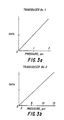
- Fig. 3b is a graphical representation of the output obtainable from a second transducer used in the second embodiment of the invention.
- a sensor 5 which may be any one of a strain gauge, a capacitive pressure sensor, or an inductive pressure sensor, measures pressure in a fluid line (not shown).
- a first transducer 10 is denoted in Fig. 1 as No. 1 and operates in a low pressure range of, for example, zero to two pounds per square inch.
- a second transducer 20 is denoted as No. 2 and operates in a high pressure range of, for example, zero to 15 pounds per square inch.
- a fluid line 30 for measured pressure branches into two ports 31 and 32 leading to the transducers 10 and 20, respectively. Thus, the ports 31 and 32 are effectively connected together in parallel so that the transducers 10 and 20 are exposed to the same measured pressure.
- a fluid line 40 for a reference pressure branches into two ports 41 and 42, also leading to the transducers 10 and 20, respectively; thus, the ports 41 and 42 are effectively connected together in parallel so that the transducers 10 and 20 are exposed to the same reference pressure.
- strain gauges can be exposed to large overpressures without being damaged. Also, this arrangement is made possible because these strain gauges can be exposed to large overpressures without undergoing any significant pressure hysteresis. In other words, subjecting the strain gauge to pressures substantially greater than the pressures of the working range of the strain gauge does not adversely affect the accuracy of the strain gauge on subsequent measurements within the working range thereof.
- An electronic signal or output from the low-range transducer 10 is routed via a first electrical line 15 to a first instrumentation amplifier 50 which amplifies the low-level output in millivolts to a high-level output in the range of about one volt to five volts maximum.
- a second electrical line 25 is routed via a second instrumentation amplifier 60 which likewise amplifies the low-level output in millivolts to a high-level output in the same range of about one volt to five volts maximum.
- the amplified output from the first instrumentation amplifier 50 is then routed via a third electrical line 55 to a comparator 70.
- the amplified output from the second instrumentation amplifier 60 is also routed via a fourth electrical line 65 to the comparator 70.
- additional strain gauge transducers with successively broader operative pressure ranges may be added when larger overall ranges of pressure are to be measured, each of the added transducers also furnishing an output signal which is amplified and supplied as an input to the comparator 70.
- the comparator circuit 70 selects from among the various inputs the one input for which the respective pressure transducer is outputing at a level most closely approaching, but below, the full range or maximum measurable pressure level for that respective transducer and generates, from the selected input, an output signal which is transmitted via a fifth electrical line 75 to a visual display or other datarecording device (not shown).
- the selection function may be accomplished by continuously monitoring the signal generated by one of the transducers, for example, the high-range transducer 20, to determine if the monitored signal is below or above a predetermined threshold level, such as 12% of the full range or maximum signal level corresponding to the monitored transducer, with the low-range transducer signal being selected for output signal generation when the monitored signal is below the threshold level and the high-range transducer being selected otherwise.
- a predetermined threshold level such as 12% of the full range or maximum signal level corresponding to the monitored transducer
- threshold levels for rising and falling monitored signal levels are, preferably, employed.
- selection of the output signal may be accomplished by a monitoring of the level of the signal generated by the intermediate-range transducer with respect to separate lower and upper threshold levels at, for example, 30% and 75%, respectively, of the full-range signal for this transducer, with the low-range transducer signal being selected when the monitored signal level is below the lower threshold, the high-range transducer signal being selected when the monitored signal level is above the upper threshold, and the intermediate-range transducer signal being selected when the monitored signal level is within the limits of the lower and upper thresholds.
- configurations having more than three pressure transducers may employ output signal selection arrangements involving the separate monitoring of the signals from each of the intermediate-range transducers with corresponding lower and upper threshold levels.
- the comparator output signal over the line 75 may be "nested", as illustrated in Fig. 2, so that the output signal of the comparator circuit 70 continuously increases in voltage with increasing pressure. This nesting is accomplished by varying the gain and the offset of the comparator output generating circuit in accordance with the identity of the one transducer signal which has been selected to generate thesignal over the line 75. In this mode, the output signal appears as that of a single transducer operable over the entire pressure range. As is shown in Fig. 2, the output signal is generated from the signal produced by the low-range transducer 10 when the sensed pressure is two pounds per square inch (psi) or less while the signal produced by the high-range transducer 20 is employed when the sensed pressure is above two psi.
- psi pounds per square inch
- an output selection switch 80 is provided, communicating with the comparator 70 via a sixth electrical line 85.
- a second output mode is shown in Figs. 3a and 3b.
- the full-range signal of the selected pressure transducer is output without conditioning of the signal and is accompanied by an identification of the selected transducer.
- the selection switch also provides for outputing of the signal corresponding to any one of the transducers without regard to whether this transducer is the one selected by the comparator 70.
- the present invention will appear as a compound transducer using either manual selection or automatic selection, but with higher accuracy over larger pressure levels than a single standard transducer subject to variable amplification.
- the circuit is designed to provide output in one of two modes: first, the nested mode in which a single output signal is generated throughout the full pressure range regardless of which one of the transducers is selected as active; and second, the manually selected mode in which the user selects one of the transducers to furnish the output signal.
- Fig. 2 is a depiction of the output in the first nested mode while Figs. 3a and 3b illustrate the output in the second full mode.
- the legend at the top indicates which one of the two transducers is active at a given pressure.
- this transducer 10 is active and the output of the high-pressure transducer 20 is ignored.
- the measured pressure exceeds that upper limit, the situation is reversed.
- the pressure range for each transducer is given on the abscissa of the corresponding graph.
- the identification of the transducer No. 1 or No. 2 is needed because, in this mode, the output signal includes both the measured pressure and an identification of the particular transducer 10 or 20.
- the present invention may also involve the organization of several units shown in Fig. 1 into one or more groups for the measurement of more than one fluid pressure at the same time. Multiplexing of the various electronic signals or outputs 75 would then be possible, thus providing the invention with a capability similar to that of either mechanically or electrically scanned fluid pressure measuring systems.
- the automatic transducer selection system of the present invention for pressure measurement can be applied in any research environment where standard pressure transducers are used.
- the inventive system may be especially advantageously used in environments where the measured pressure varies over a wide range, such as in the measurement of fluid pressure in airfoil wakes, and in situations where a reliable estimate of the fluid pressure needed for proper transducer selection is not known beforehand.
Landscapes
- Physics & Mathematics (AREA)
- General Physics & Mathematics (AREA)
- Measuring Fluid Pressure (AREA)
Abstract
Description
- The invention relates to measuring and testing generally and to fluid pressure measurement, in particular.
- There are several methods for the measurement of pressures in fluid dynamics research. One particularly useful approach employs either piezoresistive or metallic strain gauges bonded to either a silicon or a stainless steel diaphragm. With the proper compensation procedures to account for zero balance and thermal effects, these devices are very useful in the determination of fluid pressure levels in wind tunnels and other environments and also are sufficiently inexpensive to allow large numbers to be used in a research facility.
- As with any other strain gauge device, there are limits to the range and accuracy of this specific strain gauge installation. For example, the accuracy of these devices depends upon the minute deflection of a thin diaphragm with a strain gauge installed on its surface. The application of pressure to this diaphragm causes it to deflect, thus introducing in the surface a strain which is detected by the strain gauge and which is also proportional to the load applied. Appropriate calibration and compensation procedures permit the applied pressure to be measured as a function of the electrical output of the strain gauge.
- Range limitations occur because of the inherent restriction imposed by the applied pressure level to which the diaphragm can be exposed before exceeding either its linear response range or its ultimate stress limit, thus deforming the diaphragm and the strain gauge into a region of either nonrepeatable results or failure.
- In order to obtain maximum accuracy, it is desirable to maximize the amount of deflection. In other words, it is preferable to obtain a large deflection for a small applied pressure. However, in doing so, a transducer is limited in its amount of permissible overpressure, thus limiting its range of accurate measurement.
- This conflict between desired accuracy and maximum range results in users being left with a choice between very accurate transducers with a limited range of safe overpressure and less accurate transducers that can be safely exposed to a wide range of high overpressure.
- One method of minimizing this problematic choice involves electronic conditioning and amplifying of the output signal using a so-called autoranging technique by which a variable gain is applied to the strain gauge output such that the final output simulates a nearly full scale reading, regardless of the applied pressure.
- A major disadvantage of this method is that noise is also amplified along with the electrical signal. Furthermore, the output is still in reality the result of a small movement of the diaphragm.
- Thus, the solution before undertaking most tests is to match carefully the transducer size with the pressure range expected to be encountered. Of course, this solution is not applicable to tests wherein the measured fluid pressure varies over a wide range.
- Two or more pressure transducers of different ranges are used with a circuit that electronically selects the output from the transducer reading closest to full scale. Each successive transducer has a larger range than its preceding transducer. For example, a first transducer may have a scale of zero to two pounds per square inch and a second transducer may have a scale of zero to 15 pounds per square inch.
- A primary feature of the invention is to have all of the pressure ports connected together in parallel so that all transducers are exposed to the same pressure. Similarly, all reference ports are also connected together.
- A further object of the invention is to rely on the use of a new generation of pressure transducers with strain gauges fabricated as an integral part of the diaphragm. A key advantage of these strain gauges is that they are capable of being exposed to large overpressures without damage and with a lack of any significant pressure hysteresis.
- The results achieved by the invention are made possible because the strain gauges associated with this new generation of pressure transducers can be exposed to large overpressures without being damaged and with a lack of any significant pressure hysteresis.
- These and other features, objects and results obtained by the invention will become more readily apparent from a review of the following brief description of the drawings and the subsequent detailed description of the preferred embodiments.
- Fig. 1 is a schematic representation of a first embodiment of the invention.
- Fig. 2 is a graphical representation of the possible results obtainable by the first embodiment of the invention.
- Fig. 3a is a graphical representation of the output obtainable from a first transducer used in a second embodiment of the invention.
- Fig. 3b is a graphical representation of the output obtainable from a second transducer used in the second embodiment of the invention.
- A schematic representation of a first embodiment of the invention is shown in Fig. 1. Initially, a
sensor 5, which may be any one of a strain gauge, a capacitive pressure sensor, or an inductive pressure sensor, measures pressure in a fluid line (not shown). Afirst transducer 10 is denoted in Fig. 1 as No. 1 and operates in a low pressure range of, for example, zero to two pounds per square inch. Asecond transducer 20 is denoted as No. 2 and operates in a high pressure range of, for example, zero to 15 pounds per square inch. Afluid line 30 for measured pressure branches into twoports transducers ports transducers fluid line 40 for a reference pressure branches into twoports 41 and 42, also leading to thetransducers ports 41 and 42 are effectively connected together in parallel so that thetransducers - This arrangement is made possible because, for example, these strain gauges can be exposed to large overpressures without being damaged. Also, this arrangement is made possible because these strain gauges can be exposed to large overpressures without undergoing any significant pressure hysteresis. In other words, subjecting the strain gauge to pressures substantially greater than the pressures of the working range of the strain gauge does not adversely affect the accuracy of the strain gauge on subsequent measurements within the working range thereof.
- An electronic signal or output from the low-
range transducer 10 is routed via a firstelectrical line 15 to afirst instrumentation amplifier 50 which amplifies the low-level output in millivolts to a high-level output in the range of about one volt to five volts maximum. At the same time, an electronic signal or output from thehigh range transducer 20 is routed via a second electrical line 25 to asecond instrumentation amplifier 60 which likewise amplifies the low-level output in millivolts to a high-level output in the same range of about one volt to five volts maximum. The amplified output from thefirst instrumentation amplifier 50 is then routed via a thirdelectrical line 55 to acomparator 70. Similarly, the amplified output from thesecond instrumentation amplifier 60 is also routed via a fourthelectrical line 65 to thecomparator 70. It will be readily apparent that, while two transducers have been illustrated, additional strain gauge transducers with successively broader operative pressure ranges may be added when larger overall ranges of pressure are to be measured, each of the added transducers also furnishing an output signal which is amplified and supplied as an input to thecomparator 70. - The
comparator circuit 70 selects from among the various inputs the one input for which the respective pressure transducer is outputing at a level most closely approaching, but below, the full range or maximum measurable pressure level for that respective transducer and generates, from the selected input, an output signal which is transmitted via a fifthelectrical line 75 to a visual display or other datarecording device (not shown). In the illustrated two-transducer arrangement, the selection function may be accomplished by continuously monitoring the signal generated by one of the transducers, for example, the high-range transducer 20, to determine if the monitored signal is below or above a predetermined threshold level, such as 12% of the full range or maximum signal level corresponding to the monitored transducer, with the low-range transducer signal being selected for output signal generation when the monitored signal is below the threshold level and the high-range transducer being selected otherwise. - In order to prevent oscillation or hunting, separate threshold levels for rising and falling monitored signal levels are, preferably, employed. In a three-transducer configuration, selection of the output signal may be accomplished by a monitoring of the level of the signal generated by the intermediate-range transducer with respect to separate lower and upper threshold levels at, for example, 30% and 75%, respectively, of the full-range signal for this transducer, with the low-range transducer signal being selected when the monitored signal level is below the lower threshold, the high-range transducer signal being selected when the monitored signal level is above the upper threshold, and the intermediate-range transducer signal being selected when the monitored signal level is within the limits of the lower and upper thresholds. In a similar manner, configurations having more than three pressure transducers may employ output signal selection arrangements involving the separate monitoring of the signals from each of the intermediate-range transducers with corresponding lower and upper threshold levels.
- The comparator output signal over the
line 75 may be "nested", as illustrated in Fig. 2, so that the output signal of thecomparator circuit 70 continuously increases in voltage with increasing pressure. This nesting is accomplished by varying the gain and the offset of the comparator output generating circuit in accordance with the identity of the one transducer signal which has been selected to generate thesignal over theline 75. In this mode, the output signal appears as that of a single transducer operable over the entire pressure range. As is shown in Fig. 2, the output signal is generated from the signal produced by the low-range transducer 10 when the sensed pressure is two pounds per square inch (psi) or less while the signal produced by the high-range transducer 20 is employed when the sensed pressure is above two psi. - Other forms of the output signal may be provided and, for this purpose, an
output selection switch 80 is provided, communicating with thecomparator 70 via a sixthelectrical line 85. - A second output mode is shown in Figs. 3a and 3b. In this full mode, the full-range signal of the selected pressure transducer is output without conditioning of the signal and is accompanied by an identification of the selected transducer. The selection switch also provides for outputing of the signal corresponding to any one of the transducers without regard to whether this transducer is the one selected by the
comparator 70. - In the two alternative embodiments discussed above, the present invention will appear as a compound transducer using either manual selection or automatic selection, but with higher accuracy over larger pressure levels than a single standard transducer subject to variable amplification.
- To summarize the invention, the circuit is designed to provide output in one of two modes: first, the nested mode in which a single output signal is generated throughout the full pressure range regardless of which one of the transducers is selected as active; and second, the manually selected mode in which the user selects one of the transducers to furnish the output signal. Fig. 2 is a depiction of the output in the first nested mode while Figs. 3a and 3b illustrate the output in the second full mode.
- In regard to Fig. 2, the legend at the top indicates which one of the two transducers is active at a given pressure. Thus, when the measured pressure is below the upper limit of the low-pressure transducer No. 1, this
transducer 10 is active and the output of the high-pressure transducer 20 is ignored. When the measured pressure exceeds that upper limit, the situation is reversed. - In regard to Figs. 3a and 3b, the pressure range for each transducer is given on the abscissa of the corresponding graph. The identification of the transducer No. 1 or No. 2 is needed because, in this mode, the output signal includes both the measured pressure and an identification of the
particular transducer - The present invention may also involve the organization of several units shown in Fig. 1 into one or more groups for the measurement of more than one fluid pressure at the same time. Multiplexing of the various electronic signals or
outputs 75 would then be possible, thus providing the invention with a capability similar to that of either mechanically or electrically scanned fluid pressure measuring systems. - Furthermore, the automatic transducer selection system of the present invention for pressure measurement can be applied in any research environment where standard pressure transducers are used. The inventive system may be especially advantageously used in environments where the measured pressure varies over a wide range, such as in the measurement of fluid pressure in airfoil wakes, and in situations where a reliable estimate of the fluid pressure needed for proper transducer selection is not known beforehand.
- The foregoing preferred embodiments are considered illustrative only. Numerous other modifications may readily occur to those persons skilled in electronics technology after reading this specification. Consequently, the disclosed invention is not limited by the exact construction and operation shown and described above but rather is defined by the claims appended hereto.
Claims (7)
- A fluid pressure measurement system comprising:
at least two pressure transducers having successively broader effective pressure sensing ranges, each of the pressure transducers being capable of being subjected to an overpressure equal to a maximum pressure of the sensing ranges without an adverse effect therein;
means for connecting the transducers in parallel to the fluid pressure being measured and to a reference fluid pressure; and
comparator circuit means for receiving an output signal from each of the transducers, said circuit means functioning to select one of the transducer output signals which most closely approaches a full-range output signal of a corresponding transducer, said circuit means also functioning to generate an output signal from the selected transducer output signal. - The fluid pressure measurement system according to claim 1, wherein:
said comparator circuit means includes means for conditioning the output signal therefrom in accordance with the selected one of the transducer output signals. - The fluid pressure measurement system according to claim 1, wherein:
said comparator circuit means functions to generate selectively either a conditioned output signal or an output signal corresponding to the selected transducer output signal, said corresponding output signal including identification of the selected transducer. - The fluid pressure measurement system according to claim 3, further comprising:
switch means for selecting an output signal from among the output signals generated by the comparator circuit means. - The fluid pressure measurement system according to claim 1, wherein:
said pressure transducers are strain gauge-type transducers. - The fluid pressure measurement system according to claim 1, wherein:
said pressure transducers are capacitive sensing transducers. - The fluid pressure measurement system according to claim 1, wherein:
said pressure transducers are inductive sensing transducers.
Applications Claiming Priority (2)
| Application Number | Priority Date | Filing Date | Title |
|---|---|---|---|
| US532697 | 1990-06-04 | ||
| US07/532,697 US5024100A (en) | 1990-06-04 | 1990-06-04 | Automatic transducer selection system for pressure measurement |
Publications (2)
| Publication Number | Publication Date |
|---|---|
| EP0460498A2 true EP0460498A2 (en) | 1991-12-11 |
| EP0460498A3 EP0460498A3 (en) | 1992-08-19 |
Family
ID=24122802
Family Applications (1)
| Application Number | Title | Priority Date | Filing Date |
|---|---|---|---|
| EP19910108645 Ceased EP0460498A3 (en) | 1990-06-04 | 1991-05-28 | Automatic transducer selection system for pressure measurement |
Country Status (5)
| Country | Link |
|---|---|
| US (2) | US5024100A (en) |
| EP (1) | EP0460498A3 (en) |
| JP (1) | JPH04232436A (en) |
| CA (1) | CA2043688A1 (en) |
| DE (1) | DE460498T1 (en) |
Cited By (2)
| Publication number | Priority date | Publication date | Assignee | Title |
|---|---|---|---|---|
| GB2462309A (en) * | 2008-08-01 | 2010-02-03 | Cary Ratner | Pressure gauge with two pressure sensors |
| WO2020177953A1 (en) * | 2019-03-06 | 2020-09-10 | Robert Bosch Gmbh | Pressure sensor assembly |
Families Citing this family (15)
| Publication number | Priority date | Publication date | Assignee | Title |
|---|---|---|---|---|
| CH688210A5 (en) * | 1993-12-15 | 1997-06-13 | Balzers Hochvakuum | Pressure measuring methods and pressure measurement arrangement for its execution |
| US6047244A (en) * | 1997-12-05 | 2000-04-04 | Rosemount Inc. | Multiple range transition method and apparatus for process control sensors |
| WO2005083539A1 (en) * | 2004-02-28 | 2005-09-09 | Abb Research Ltd. | Process control system and method for operating a system of this type |
| JP2006177833A (en) * | 2004-12-24 | 2006-07-06 | Yokogawa Electric Corp | Differential pressure transmitter |
| US7207224B2 (en) * | 2005-06-10 | 2007-04-24 | Brooks Automation, Inc. | Wide-range combination vacuum gauge |
| US7418869B2 (en) * | 2005-06-10 | 2008-09-02 | Brooks Automation, Inc. | Wide-range combination vacuum gauge |
| JP4668027B2 (en) * | 2005-10-17 | 2011-04-13 | シーケーディ株式会社 | Chemical supply system |
| JP5044423B2 (en) * | 2008-01-16 | 2012-10-10 | トヨタ自動車株式会社 | Pressure detection device |
| JP5375252B2 (en) * | 2008-11-28 | 2013-12-25 | 富士電機株式会社 | Vacuum gauge |
| US7997143B2 (en) * | 2009-04-09 | 2011-08-16 | Kulite Semiconductor Products, Inc. | Internally switched multiple range transducer |
| US9804050B2 (en) * | 2013-03-14 | 2017-10-31 | Kulite Semiconductor Products, Inc. | Systems and methods for sensor drift compensation |
| JP6480837B2 (en) * | 2015-09-04 | 2019-03-13 | 株式会社東芝 | Sensor, information terminal, microphone, blood pressure sensor, and touch panel |
| US10612991B1 (en) * | 2017-08-25 | 2020-04-07 | Fluke Corporation | High dynamic range capacitive pressure sensor |
| US11415474B2 (en) * | 2020-06-15 | 2022-08-16 | The Boeing Company | Pressure sensor and system for measuring pressure |
| CN114813031B (en) * | 2022-07-01 | 2022-09-30 | 中国航空工业集团公司沈阳空气动力研究所 | Wide-range high-precision pressure measuring device and method for wind tunnel test |
Family Cites Families (11)
| Publication number | Priority date | Publication date | Assignee | Title |
|---|---|---|---|---|
| US3118305A (en) * | 1964-01-21 | Manometer system | ||
| DE2347543A1 (en) * | 1973-09-21 | 1975-04-03 | Leybold Heraeus Gmbh & Co Kg | Vacuum measurement on two different measuring principles - with heat conductivity vacuum gauge combined with aneroid vacuum gauge |
| US4339943A (en) * | 1980-08-05 | 1982-07-20 | Smiths Industries Limited | Pressure transducer cross-check system |
| US4375243A (en) * | 1981-03-30 | 1983-03-01 | Doll W Gary | Wide range high accuracy weighing and counting scale |
| DE3120085C2 (en) * | 1981-05-20 | 1985-02-28 | Interatom Internationale Atomreaktorbau Gmbh, 5060 Bergisch Gladbach | Differential pressure measuring device with measuring point switchover option |
| US4445383A (en) * | 1982-06-18 | 1984-05-01 | General Signal Corporation | Multiple range capacitive pressure transducer |
| US4537079A (en) * | 1984-03-13 | 1985-08-27 | Lee Arnold S J | Multi-pressure manometer |
| US4776219A (en) * | 1987-04-06 | 1988-10-11 | Jaromir Friedrich | Pressure transducer |
| US4827772A (en) * | 1987-10-19 | 1989-05-09 | Texaco Inc. | Differential pressure sensing means and method |
| US4818994A (en) * | 1987-10-22 | 1989-04-04 | Rosemount Inc. | Transmitter with internal serial bus |
| FR2646237B1 (en) * | 1989-04-21 | 1994-01-07 | Fabrication Instruments Mesure | HIGH-PRESSURE GAS GAUGE DEVICE, PARTICULARLY FOR THE RESERVATION OF GASEOUS OXYGEN ON BOARD AN AIRCRAFT |
-
1990
- 1990-06-04 US US07/532,697 patent/US5024100A/en not_active Ceased
-
1991
- 1991-05-28 EP EP19910108645 patent/EP0460498A3/en not_active Ceased
- 1991-05-28 DE DE199191108645T patent/DE460498T1/en active Pending
- 1991-05-31 CA CA002043688A patent/CA2043688A1/en not_active Abandoned
- 1991-06-04 JP JP3132879A patent/JPH04232436A/en active Pending
-
1993
- 1993-05-14 US US08/060,979 patent/USRE34694E/en not_active Expired - Lifetime
Cited By (4)
| Publication number | Priority date | Publication date | Assignee | Title |
|---|---|---|---|---|
| GB2462309A (en) * | 2008-08-01 | 2010-02-03 | Cary Ratner | Pressure gauge with two pressure sensors |
| GB2462309B (en) * | 2008-08-01 | 2012-05-30 | Cary Ratner | Pressure gauge |
| WO2020177953A1 (en) * | 2019-03-06 | 2020-09-10 | Robert Bosch Gmbh | Pressure sensor assembly |
| CN113874696A (en) * | 2019-03-06 | 2021-12-31 | 罗伯特·博世有限公司 | Pressure sensor assembly |
Also Published As
| Publication number | Publication date |
|---|---|
| US5024100A (en) | 1991-06-18 |
| USRE34694E (en) | 1994-08-16 |
| CA2043688A1 (en) | 1991-12-05 |
| EP0460498A3 (en) | 1992-08-19 |
| DE460498T1 (en) | 1992-04-09 |
| JPH04232436A (en) | 1992-08-20 |
Similar Documents
| Publication | Publication Date | Title |
|---|---|---|
| US5024100A (en) | Automatic transducer selection system for pressure measurement | |
| EP0799412B1 (en) | AC excitation of polysilicon based pressure sensors | |
| US5341687A (en) | 3-dimensional pressure sensor | |
| US5259248A (en) | Integrated multisensor and static and differential pressure transmitter and plant system using the integrated multisensor | |
| EP0803054B1 (en) | A temperature compensation method in pressure sensors | |
| US9291516B2 (en) | Internally switched multiple range transducers | |
| CN111623922A (en) | Method for evaluating uncertainty of zero correction value of pressure transmitter | |
| US3863493A (en) | Compensated fluidic bearing clearance monitor | |
| Watson | A recording field tensiometer with rapid response characteristics | |
| US5185709A (en) | Apparatus and method for measuring pressure changes within pressure vessels | |
| GB2121185A (en) | Flow sensor for breath and other gas analysers | |
| GB2113845A (en) | Monitoring loads in rotating bearings | |
| Wilson | Strain-gage instrumentation | |
| JP3145040B2 (en) | Capacitive acceleration sensor | |
| US20020171629A1 (en) | Low power measurement circuit for position sensor | |
| Šiškovski et al. | Development of system for displacement measurement of a cantilever beam with strain gauge sensor | |
| US4720999A (en) | Universal pressure transducer | |
| US4614118A (en) | Non-compliant pressure cell | |
| US3714827A (en) | Variable time base integrator circuit for buffet signal measurements | |
| JPH05107090A (en) | Differential pressure flow meter | |
| Mbacke et al. | Analog, compact and economical solution for the compensation of implantable piezoresistive blood pressure sensors for wireless medical monitoring | |
| KR102471346B1 (en) | Vacuum Pressure Calculator | |
| Nisbet | A modification to convert two dead weight gauges into a direct reading differential manometer | |
| JPH0278924A (en) | Pressure detector | |
| Chioibas | Aspects regarding some equipment used to research the drawing process |
Legal Events
| Date | Code | Title | Description |
|---|---|---|---|
| PUAI | Public reference made under article 153(3) epc to a published international application that has entered the european phase |
Free format text: ORIGINAL CODE: 0009012 |
|
| AK | Designated contracting states |
Kind code of ref document: A2 Designated state(s): DE FR GB IT NL SE |
|
| ITCL | It: translation for ep claims filed |
Representative=s name: BUGNION S.P.A. |
|
| EL | Fr: translation of claims filed | ||
| DET | De: translation of patent claims | ||
| PUAL | Search report despatched |
Free format text: ORIGINAL CODE: 0009013 |
|
| AK | Designated contracting states |
Kind code of ref document: A3 Designated state(s): DE FR GB IT NL SE |
|
| 17P | Request for examination filed |
Effective date: 19921224 |
|
| 17Q | First examination report despatched |
Effective date: 19931228 |
|
| STAA | Information on the status of an ep patent application or granted ep patent |
Free format text: STATUS: THE APPLICATION HAS BEEN REFUSED |
|
| 18R | Application refused |
Effective date: 19950205 |