EP0460286A2 - Method and arrangement for bonding a semiconductor component to a substrate or for finishing a semiconductor/substrate connection by contactless pressing - Google Patents
Method and arrangement for bonding a semiconductor component to a substrate or for finishing a semiconductor/substrate connection by contactless pressing Download PDFInfo
- Publication number
- EP0460286A2 EP0460286A2 EP90123453A EP90123453A EP0460286A2 EP 0460286 A2 EP0460286 A2 EP 0460286A2 EP 90123453 A EP90123453 A EP 90123453A EP 90123453 A EP90123453 A EP 90123453A EP 0460286 A2 EP0460286 A2 EP 0460286A2
- Authority
- EP
- European Patent Office
- Prior art keywords
- semiconductor
- substrate
- plunger
- pressure
- pierced
- Prior art date
- Legal status (The legal status is an assumption and is not a legal conclusion. Google has not performed a legal analysis and makes no representation as to the accuracy of the status listed.)
- Withdrawn
Links
Images

Classifications
-
- H—ELECTRICITY
- H01—ELECTRIC ELEMENTS
- H01L—SEMICONDUCTOR DEVICES NOT COVERED BY CLASS H10
- H01L21/00—Processes or apparatus adapted for the manufacture or treatment of semiconductor or solid state devices or of parts thereof
- H01L21/67—Apparatus specially adapted for handling semiconductor or electric solid state devices during manufacture or treatment thereof; Apparatus specially adapted for handling wafers during manufacture or treatment of semiconductor or electric solid state devices or components ; Apparatus not specifically provided for elsewhere
- H01L21/67005—Apparatus not specifically provided for elsewhere
- H01L21/67011—Apparatus for manufacture or treatment
- H01L21/67121—Apparatus for making assemblies not otherwise provided for, e.g. package constructions
-
- H—ELECTRICITY
- H01—ELECTRIC ELEMENTS
- H01L—SEMICONDUCTOR DEVICES NOT COVERED BY CLASS H10
- H01L21/00—Processes or apparatus adapted for the manufacture or treatment of semiconductor or solid state devices or of parts thereof
- H01L21/02—Manufacture or treatment of semiconductor devices or of parts thereof
- H01L21/04—Manufacture or treatment of semiconductor devices or of parts thereof the devices having at least one potential-jump barrier or surface barrier, e.g. PN junction, depletion layer or carrier concentration layer
- H01L21/50—Assembly of semiconductor devices using processes or apparatus not provided for in a single one of the subgroups H01L21/06 - H01L21/326, e.g. sealing of a cap to a base of a container
- H01L21/56—Encapsulations, e.g. encapsulation layers, coatings
- H01L21/565—Moulds
-
- H—ELECTRICITY
- H01—ELECTRIC ELEMENTS
- H01L—SEMICONDUCTOR DEVICES NOT COVERED BY CLASS H10
- H01L24/00—Arrangements for connecting or disconnecting semiconductor or solid-state bodies; Methods or apparatus related thereto
- H01L24/74—Apparatus for manufacturing arrangements for connecting or disconnecting semiconductor or solid-state bodies
- H01L24/75—Apparatus for connecting with bump connectors or layer connectors
-
- H—ELECTRICITY
- H01—ELECTRIC ELEMENTS
- H01L—SEMICONDUCTOR DEVICES NOT COVERED BY CLASS H10
- H01L24/00—Arrangements for connecting or disconnecting semiconductor or solid-state bodies; Methods or apparatus related thereto
- H01L24/80—Methods for connecting semiconductor or other solid state bodies using means for bonding being attached to, or being formed on, the surface to be connected
- H01L24/83—Methods for connecting semiconductor or other solid state bodies using means for bonding being attached to, or being formed on, the surface to be connected using a layer connector
-
- H—ELECTRICITY
- H01—ELECTRIC ELEMENTS
- H01L—SEMICONDUCTOR DEVICES NOT COVERED BY CLASS H10
- H01L2224/00—Indexing scheme for arrangements for connecting or disconnecting semiconductor or solid-state bodies and methods related thereto as covered by H01L24/00
- H01L2224/01—Means for bonding being attached to, or being formed on, the surface to be connected, e.g. chip-to-package, die-attach, "first-level" interconnects; Manufacturing methods related thereto
- H01L2224/26—Layer connectors, e.g. plate connectors, solder or adhesive layers; Manufacturing methods related thereto
- H01L2224/27—Manufacturing methods
- H01L2224/275—Manufacturing methods by chemical or physical modification of a pre-existing or pre-deposited material
- H01L2224/27505—Sintering
-
- H—ELECTRICITY
- H01—ELECTRIC ELEMENTS
- H01L—SEMICONDUCTOR DEVICES NOT COVERED BY CLASS H10
- H01L2224/00—Indexing scheme for arrangements for connecting or disconnecting semiconductor or solid-state bodies and methods related thereto as covered by H01L24/00
- H01L2224/01—Means for bonding being attached to, or being formed on, the surface to be connected, e.g. chip-to-package, die-attach, "first-level" interconnects; Manufacturing methods related thereto
- H01L2224/26—Layer connectors, e.g. plate connectors, solder or adhesive layers; Manufacturing methods related thereto
- H01L2224/28—Structure, shape, material or disposition of the layer connectors prior to the connecting process
- H01L2224/29—Structure, shape, material or disposition of the layer connectors prior to the connecting process of an individual layer connector
- H01L2224/29001—Core members of the layer connector
- H01L2224/29099—Material
- H01L2224/29198—Material with a principal constituent of the material being a combination of two or more materials in the form of a matrix with a filler, i.e. being a hybrid material, e.g. segmented structures, foams
- H01L2224/29298—Fillers
- H01L2224/29299—Base material
- H01L2224/293—Base material with a principal constituent of the material being a metal or a metalloid, e.g. boron [B], silicon [Si], germanium [Ge], arsenic [As], antimony [Sb], tellurium [Te] and polonium [Po], and alloys thereof
- H01L2224/29338—Base material with a principal constituent of the material being a metal or a metalloid, e.g. boron [B], silicon [Si], germanium [Ge], arsenic [As], antimony [Sb], tellurium [Te] and polonium [Po], and alloys thereof the principal constituent melting at a temperature of greater than or equal to 950°C and less than 1550°C
- H01L2224/29339—Silver [Ag] as principal constituent
-
- H—ELECTRICITY
- H01—ELECTRIC ELEMENTS
- H01L—SEMICONDUCTOR DEVICES NOT COVERED BY CLASS H10
- H01L2224/00—Indexing scheme for arrangements for connecting or disconnecting semiconductor or solid-state bodies and methods related thereto as covered by H01L24/00
- H01L2224/74—Apparatus for manufacturing arrangements for connecting or disconnecting semiconductor or solid-state bodies and for methods related thereto
- H01L2224/75—Apparatus for connecting with bump connectors or layer connectors
- H01L2224/7525—Means for applying energy, e.g. heating means
- H01L2224/753—Means for applying energy, e.g. heating means by means of pressure
- H01L2224/75301—Bonding head
- H01L2224/75302—Shape
- H01L2224/75303—Shape of the pressing surface
- H01L2224/75305—Shape of the pressing surface comprising protrusions
-
- H—ELECTRICITY
- H01—ELECTRIC ELEMENTS
- H01L—SEMICONDUCTOR DEVICES NOT COVERED BY CLASS H10
- H01L2224/00—Indexing scheme for arrangements for connecting or disconnecting semiconductor or solid-state bodies and methods related thereto as covered by H01L24/00
- H01L2224/74—Apparatus for manufacturing arrangements for connecting or disconnecting semiconductor or solid-state bodies and for methods related thereto
- H01L2224/75—Apparatus for connecting with bump connectors or layer connectors
- H01L2224/757—Means for aligning
- H01L2224/75743—Suction holding means
- H01L2224/75745—Suction holding means in the upper part of the bonding apparatus, e.g. in the bonding head
-
- H—ELECTRICITY
- H01—ELECTRIC ELEMENTS
- H01L—SEMICONDUCTOR DEVICES NOT COVERED BY CLASS H10
- H01L2224/00—Indexing scheme for arrangements for connecting or disconnecting semiconductor or solid-state bodies and methods related thereto as covered by H01L24/00
- H01L2224/80—Methods for connecting semiconductor or other solid state bodies using means for bonding being attached to, or being formed on, the surface to be connected
- H01L2224/83—Methods for connecting semiconductor or other solid state bodies using means for bonding being attached to, or being formed on, the surface to be connected using a layer connector
- H01L2224/83001—Methods for connecting semiconductor or other solid state bodies using means for bonding being attached to, or being formed on, the surface to be connected using a layer connector involving a temporary auxiliary member not forming part of the bonding apparatus
- H01L2224/83002—Methods for connecting semiconductor or other solid state bodies using means for bonding being attached to, or being formed on, the surface to be connected using a layer connector involving a temporary auxiliary member not forming part of the bonding apparatus being a removable or sacrificial coating
-
- H—ELECTRICITY
- H01—ELECTRIC ELEMENTS
- H01L—SEMICONDUCTOR DEVICES NOT COVERED BY CLASS H10
- H01L2224/00—Indexing scheme for arrangements for connecting or disconnecting semiconductor or solid-state bodies and methods related thereto as covered by H01L24/00
- H01L2224/80—Methods for connecting semiconductor or other solid state bodies using means for bonding being attached to, or being formed on, the surface to be connected
- H01L2224/83—Methods for connecting semiconductor or other solid state bodies using means for bonding being attached to, or being formed on, the surface to be connected using a layer connector
- H01L2224/8312—Aligning
- H01L2224/83136—Aligning involving guiding structures, e.g. spacers or supporting members
-
- H—ELECTRICITY
- H01—ELECTRIC ELEMENTS
- H01L—SEMICONDUCTOR DEVICES NOT COVERED BY CLASS H10
- H01L2224/00—Indexing scheme for arrangements for connecting or disconnecting semiconductor or solid-state bodies and methods related thereto as covered by H01L24/00
- H01L2224/80—Methods for connecting semiconductor or other solid state bodies using means for bonding being attached to, or being formed on, the surface to be connected
- H01L2224/83—Methods for connecting semiconductor or other solid state bodies using means for bonding being attached to, or being formed on, the surface to be connected using a layer connector
- H01L2224/8319—Arrangement of the layer connectors prior to mounting
-
- H—ELECTRICITY
- H01—ELECTRIC ELEMENTS
- H01L—SEMICONDUCTOR DEVICES NOT COVERED BY CLASS H10
- H01L2224/00—Indexing scheme for arrangements for connecting or disconnecting semiconductor or solid-state bodies and methods related thereto as covered by H01L24/00
- H01L2224/80—Methods for connecting semiconductor or other solid state bodies using means for bonding being attached to, or being formed on, the surface to be connected
- H01L2224/83—Methods for connecting semiconductor or other solid state bodies using means for bonding being attached to, or being formed on, the surface to be connected using a layer connector
- H01L2224/838—Bonding techniques
- H01L2224/83801—Soldering or alloying
- H01L2224/8382—Diffusion bonding
- H01L2224/8383—Solid-solid interdiffusion
-
- H—ELECTRICITY
- H01—ELECTRIC ELEMENTS
- H01L—SEMICONDUCTOR DEVICES NOT COVERED BY CLASS H10
- H01L2224/00—Indexing scheme for arrangements for connecting or disconnecting semiconductor or solid-state bodies and methods related thereto as covered by H01L24/00
- H01L2224/80—Methods for connecting semiconductor or other solid state bodies using means for bonding being attached to, or being formed on, the surface to be connected
- H01L2224/83—Methods for connecting semiconductor or other solid state bodies using means for bonding being attached to, or being formed on, the surface to be connected using a layer connector
- H01L2224/838—Bonding techniques
- H01L2224/8384—Sintering
-
- H—ELECTRICITY
- H01—ELECTRIC ELEMENTS
- H01L—SEMICONDUCTOR DEVICES NOT COVERED BY CLASS H10
- H01L2224/00—Indexing scheme for arrangements for connecting or disconnecting semiconductor or solid-state bodies and methods related thereto as covered by H01L24/00
- H01L2224/80—Methods for connecting semiconductor or other solid state bodies using means for bonding being attached to, or being formed on, the surface to be connected
- H01L2224/83—Methods for connecting semiconductor or other solid state bodies using means for bonding being attached to, or being formed on, the surface to be connected using a layer connector
- H01L2224/838—Bonding techniques
- H01L2224/8385—Bonding techniques using a polymer adhesive, e.g. an adhesive based on silicone, epoxy, polyimide, polyester
-
- H—ELECTRICITY
- H01—ELECTRIC ELEMENTS
- H01L—SEMICONDUCTOR DEVICES NOT COVERED BY CLASS H10
- H01L2224/00—Indexing scheme for arrangements for connecting or disconnecting semiconductor or solid-state bodies and methods related thereto as covered by H01L24/00
- H01L2224/80—Methods for connecting semiconductor or other solid state bodies using means for bonding being attached to, or being formed on, the surface to be connected
- H01L2224/83—Methods for connecting semiconductor or other solid state bodies using means for bonding being attached to, or being formed on, the surface to be connected using a layer connector
- H01L2224/83905—Combinations of bonding methods provided for in at least two different groups from H01L2224/838 - H01L2224/83904
- H01L2224/83907—Intermediate bonding, i.e. intermediate bonding step for temporarily bonding the semiconductor or solid-state body, followed by at least a further bonding step
-
- H—ELECTRICITY
- H01—ELECTRIC ELEMENTS
- H01L—SEMICONDUCTOR DEVICES NOT COVERED BY CLASS H10
- H01L2224/00—Indexing scheme for arrangements for connecting or disconnecting semiconductor or solid-state bodies and methods related thereto as covered by H01L24/00
- H01L2224/80—Methods for connecting semiconductor or other solid state bodies using means for bonding being attached to, or being formed on, the surface to be connected
- H01L2224/83—Methods for connecting semiconductor or other solid state bodies using means for bonding being attached to, or being formed on, the surface to be connected using a layer connector
- H01L2224/83909—Post-treatment of the layer connector or bonding area
- H01L2224/8392—Applying permanent coating, e.g. protective coating
-
- H—ELECTRICITY
- H01—ELECTRIC ELEMENTS
- H01L—SEMICONDUCTOR DEVICES NOT COVERED BY CLASS H10
- H01L2224/00—Indexing scheme for arrangements for connecting or disconnecting semiconductor or solid-state bodies and methods related thereto as covered by H01L24/00
- H01L2224/80—Methods for connecting semiconductor or other solid state bodies using means for bonding being attached to, or being formed on, the surface to be connected
- H01L2224/83—Methods for connecting semiconductor or other solid state bodies using means for bonding being attached to, or being formed on, the surface to be connected using a layer connector
- H01L2224/83909—Post-treatment of the layer connector or bonding area
- H01L2224/83951—Forming additional members, e.g. for reinforcing, fillet sealant
-
- H—ELECTRICITY
- H01—ELECTRIC ELEMENTS
- H01L—SEMICONDUCTOR DEVICES NOT COVERED BY CLASS H10
- H01L2924/00—Indexing scheme for arrangements or methods for connecting or disconnecting semiconductor or solid-state bodies as covered by H01L24/00
- H01L2924/01—Chemical elements
- H01L2924/01005—Boron [B]
-
- H—ELECTRICITY
- H01—ELECTRIC ELEMENTS
- H01L—SEMICONDUCTOR DEVICES NOT COVERED BY CLASS H10
- H01L2924/00—Indexing scheme for arrangements or methods for connecting or disconnecting semiconductor or solid-state bodies as covered by H01L24/00
- H01L2924/01—Chemical elements
- H01L2924/01006—Carbon [C]
-
- H—ELECTRICITY
- H01—ELECTRIC ELEMENTS
- H01L—SEMICONDUCTOR DEVICES NOT COVERED BY CLASS H10
- H01L2924/00—Indexing scheme for arrangements or methods for connecting or disconnecting semiconductor or solid-state bodies as covered by H01L24/00
- H01L2924/01—Chemical elements
- H01L2924/01033—Arsenic [As]
-
- H—ELECTRICITY
- H01—ELECTRIC ELEMENTS
- H01L—SEMICONDUCTOR DEVICES NOT COVERED BY CLASS H10
- H01L2924/00—Indexing scheme for arrangements or methods for connecting or disconnecting semiconductor or solid-state bodies as covered by H01L24/00
- H01L2924/01—Chemical elements
- H01L2924/01042—Molybdenum [Mo]
-
- H—ELECTRICITY
- H01—ELECTRIC ELEMENTS
- H01L—SEMICONDUCTOR DEVICES NOT COVERED BY CLASS H10
- H01L2924/00—Indexing scheme for arrangements or methods for connecting or disconnecting semiconductor or solid-state bodies as covered by H01L24/00
- H01L2924/01—Chemical elements
- H01L2924/01047—Silver [Ag]
-
- H—ELECTRICITY
- H01—ELECTRIC ELEMENTS
- H01L—SEMICONDUCTOR DEVICES NOT COVERED BY CLASS H10
- H01L2924/00—Indexing scheme for arrangements or methods for connecting or disconnecting semiconductor or solid-state bodies as covered by H01L24/00
- H01L2924/01—Chemical elements
- H01L2924/01068—Erbium [Er]
-
- H—ELECTRICITY
- H01—ELECTRIC ELEMENTS
- H01L—SEMICONDUCTOR DEVICES NOT COVERED BY CLASS H10
- H01L2924/00—Indexing scheme for arrangements or methods for connecting or disconnecting semiconductor or solid-state bodies as covered by H01L24/00
- H01L2924/01—Chemical elements
- H01L2924/01082—Lead [Pb]
-
- H—ELECTRICITY
- H01—ELECTRIC ELEMENTS
- H01L—SEMICONDUCTOR DEVICES NOT COVERED BY CLASS H10
- H01L2924/00—Indexing scheme for arrangements or methods for connecting or disconnecting semiconductor or solid-state bodies as covered by H01L24/00
- H01L2924/013—Alloys
- H01L2924/014—Solder alloys
-
- H—ELECTRICITY
- H01—ELECTRIC ELEMENTS
- H01L—SEMICONDUCTOR DEVICES NOT COVERED BY CLASS H10
- H01L2924/00—Indexing scheme for arrangements or methods for connecting or disconnecting semiconductor or solid-state bodies as covered by H01L24/00
- H01L2924/19—Details of hybrid assemblies other than the semiconductor or other solid state devices to be connected
- H01L2924/1901—Structure
- H01L2924/1904—Component type
- H01L2924/19043—Component type being a resistor
Definitions
- the invention relates to methods for connecting a semiconductor to a substrate or for the aftertreatment of a semiconductor / substrate connection by pressing, and to arrangements for carrying them out.
- connection technologies such as gluing or soldering are used for this, which can be carried out quickly, cheaply and fully automatically.
- the temperature resistance and the temperature change resistance are limited.
- the thermal and electrical resistance of the adhesive also has a disadvantageous effect.
- a high-strength connection can be achieved with low thermal and electrical resistance by pressure sintering a silver powder layer according to EP-A-242 626.
- a pressure is applied to the parts to be connected by rigid stamps.
- the top of the semiconductor is completely touched in this pressing process by a pressure-transmitting solid medium.
- EP-330 896 and EP-330 895 it is also known to embed the substrate and the semiconductor in an elastic centering mold, for example made of silicone rubber, which transmits the pressing pressure of a movable stamp by the remaining interior space when the sintering pressure is reached one Filling chamber completely, in which the substrate and the semiconductor body are located.
- an elastic centering mold for example made of silicone rubber
- the invention has for its object to provide methods of the type mentioned, in which semiconductors are advantageously connected to substrates by pressing or pre-connected semiconductor / substrate connections are advantageously treated by pressing. This is achieved according to the invention by designing the method according to the characterizing parts of patent claims 1 or 2.
- Claims 3 to 12 and 15 to 17 are directed to advantageous developments of the method according to the invention.
- Claims 13 and 14 relate to advantageous arrangements for carrying out the method according to claims 10 or 11.
- Claim 18 is directed to an advantageous arrangement for carrying out the method according to claim 15.
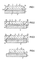
- the intermediate layer 2 lies between the semiconductor surface 5 and the substrate surface 7, which are optionally pretreated, and itself consists of a thermally and electrically highly conductive powder, for example silver powder, which is present, for example, as a pre-sintered film.
- the lateral edge surface 4a of the semiconductor 3 is bonded and sealed to an annular outer region 4b of the substrate surface 7 by an annular, elastic bead 6a, for example a silicone bead.
- an annular edge passivation 6b of a semiconductor 3a shown in FIG. 2 can be used.
- the edge passivation 6b consists of a soft and elastic plastic, for example silicone, and is shaped in such a way that the side edge surface 4c of the semiconductor 3a, which has an indentation for better fastening, is connected and sealed to a region 4d of the side edge surface of the substrate 1 .
- a ring 6c preformed from a soft and elastic plastic, for example silicone, shown in FIG. 3 can be used.
- the plastic ring 6c can either be applied to the intermediate layer 2 after the semiconductor 2 has been applied or applied together with the semiconductor 3. If the plastic ring 6c is applied, it must seal the area between the lateral edge surface 4a of the semiconductor 3 and the area 4d of the lateral edge surface of the substrate.
- an autoclave is a heatable pressure vessel, which in this case must be designed for a pressure of 300 to 400 bar and is best to have an internal heater.
- Systems for hot isostatic pressing (HIP) are particularly suitable for this.
- the pressing pressure of a chemically inert and non-solid medium located in the autoclave causes compressive forces on a surface O of the semiconductors 3 or 3a and on a surface 8 of the respective substrate 1.
- the seals 6a, 6b or 6c prevent a back pressure from building up in the intermediate layer 2; no counterforces can thus be brought about on the surfaces 5, 7 and as a result the arrangement of semiconductor, intermediate layer and substrate is pressed together.
- the intermediate layer 2 is strongly compressed by the pressure and a connection is created by pressure sintering.
- an intermediate layer 2 is dispensed with and only the optionally pretreated semiconductor surface 5 and optionally pretreated substrate surface 7 are pressed onto one another, a connection is formed in a corresponding manner by diffusion welding.
- the surfaces 5, 7 can be pretreated here, for example, by galvanic application or vapor deposition of a noble metal contacting layer.
- a pre-bonded semiconductor / substrate connection shown in FIG. 4 can be post-sintered to increase the bond strength with the help of post-treatment by contact-free pressing and at a suitable temperature.
- the semiconductor / substrate connection is also pre-connected, for example, by contact-free pressing.
- a seal between semiconductor 3 and substrate 1 is not necessary, in particular in the case of power semiconductors, since the penetration speed, even in the case of a gaseous pressure medium, is so low in the compressed intermediate layer 2a, for example consisting of silver powder, that in the case of semiconductor components, such as, for example, power semiconductor components, pressure equalization only occurs after many minutes.
- pressing takes place in an autoclave.
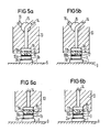
- the first method according to the invention can also be carried out by an arrangement described in FIG. 5a or FIG. 5b.
- the semiconductor 3b or 3 is located on a heating block 9 for heating.
- the semiconductor 3b has a slightly raised, annular outer region 10a, on which a pierced plunger 11a lies without a raised outer region.
- the outside area can consist of silicone lacquer, for example.
- a pierced plunger 11b has a slightly raised annular outer region and the semiconductor 3 has no corresponding outer region for this.
- the semiconductors 3b and 3 can be coated with a sinterable intermediate layer 2b, for example a silver sponge, during the connection by pressure sintering.
- the pierced plungers 11a and 11b each have a bore 12 which connects an inner region 17, which is enclosed in a ring by the associated outer region 10a or 10b, with the cylinder interior 18 of a cylinder 13.
- a three-way valve 15 enables an optional connection between the cylinder interior 18 and an inlet 14 or an outlet 16.
- the substrate 1 is preheated on the heating block 9, the pierced plunger 11a or 11b is placed on the semiconductor 3b or 3 such that a seal between the pierced plunger 11a or 11b and the semiconductor 3b or 3rd is effected. If the outlet 16 is now connected to the cylinder interior 18 by the three-way valve 15, the cylinder interior 18 and, via the bore 12, also the inner region 17 are evacuated, which causes the semiconductor 3b or 3 to be sucked in.
- the semiconductor 3b or 3 can now, together with the plunger 11a or 11b and the cylinder 13, be positioned exactly on the substrate 1 before the inlet 14 is connected to the cylinder interior 18 with the help of the three-way valve 15 and the pressing pressure of the chemically inert and non-solid medium, for example nitrogen or argon as a gaseous and silicone oil as a liquid medium, builds up in the interior 17 between the plunger and the semiconductor and presses the latter onto the preheated substrate 1 without contact.
- the chemically inert and non-solid medium for example nitrogen or argon as a gaseous and silicone oil as a liquid medium
- the arrangement for carrying out the second method according to the invention has a direct connection between the inlet 14 for the chemically inert and non-solid medium and the cylinder interior 18, since suction is carried out when the second method according to the invention is carried out for exact positioning, because the substrate 1 is already connected to the semiconductor 3b or 3 directly or through the pre-compressed intermediate layer 2a to form a semiconductor / substrate connection.
- the plastic melt required for their production for example a thermosetting synthetic resin composition
- the plastic melt required for their production can simultaneously be used as a chemically inert and non-solid medium for the first or second method according to the invention. This is possible because the encapsulation takes place at temperatures around 200 ° C and a pressure of several hundred bar with a holding time of a few minutes.
- FIG. 7 shows an arrangement for carrying out the first or second method according to the invention, in which the injection pressure of a plastic melt for connecting the semiconductors 3c and 3d to the substrates 1b and 1a through an intermediate layer 2 or for post-treating the already existing semiconductor / substrate connections 3c, 1b and 3d, 1a.
- the arrangement shown in FIG. 7 is used in particular for the production of semiconductor modules and essentially consists of an upper injection mold 23 and a lower injection mold 24, which together form an injection chamber 27, an injection channel 25 for supplying the plastic melt and a thin ventilation channel 26.
- the plastic melt under the injection pressure penetrates through the injection channel 25 into the injection chamber 27, flows around the parts located in the injection chamber and exerts a hydrostatic pressure without, however, because of their high level Viscosity penetrate into the intermediate layer 2 and build up a back pressure.
- FIG. 8 shows a further arrangement for carrying out the first or second method according to the invention, in which the injection pressure of a plastic melt for connecting a semiconductor 3e to a substrate 1c through an intermediate layer or for post-treating the already existing semiconductor / substrate connection 3e, 1c.
- the arrangement shown in FIG. 8 is used in particular for the production of semiconductor components with a wafer housing and essentially consists of an upper injection mold 23a, an intermediate mold 31 and a lower injection mold 24a, which together form an injection chamber 27a.
- the spray chamber 27a is connected via a spray channel 25a to a press chamber 29 which has a press piston 30.
- the spray chamber 27a since the spray chamber 27a only surrounds the arrangement of an upper contact piece 32, the semiconductor 3e, the substrate 1c and a lower contact piece 33, no pressing forces can be exerted on the contact pieces 32, 33 by the plastic melt of the spray chamber.
- an additional chamber 28 connected to the pressing chamber 29 via an additional injection channel 25b.
- the connection of the additional chamber to the press chamber could also be formed indirectly, for example by an additional spray channel between the additional chamber and the spray chamber. If, for example, an additional chamber is not sufficient in a special semiconductor / substrate arrangement, a plurality of additional chambers connected directly or indirectly to the press chamber can be provided.
- the spray chamber 27a has a thin ventilation channel 26a and the additional chamber 28 has a thin additional ventilation channel 26b, both ventilation channels 26a, 26b having to be so thin that the plastic melt cannot escape.
- the arrangement of the upper contact piece 32, the semiconductor 3e, the substrate 1c and the lower contact piece 33 is introduced into the lower injection mold 24a, and then the Intermediate mold 31 placed and the injection mold closed by the upper injection mold 23a.
- the press chamber is then filled with the plastic to be sprayed and the melt is injected into the mold. After the plastic melt has hardened, the injection mold is opened, the plastic material of the additional chamber is removed from the component and the finished component is removed from the injection mold.
- a press chamber can simultaneously supply several injection molds with the plastic melt, so that several components can be encapsulated in one operation.
- the first and second methods according to the invention are primarily intended for the processing of entire semiconductor wafers, but can also be applied to semiconductor chips without problems.
Abstract
Die Erfindung betrifft Verfahren, bei denen durch ein chemisch inertes und nicht festes Medium Druck auf eine Halbleiteroberfläche (0) ausgeübt wird,wobei zum Beispiel mit Hilfe einer Abdichtung (6a) verhindert wird, daß sich ein Gegendruck in einer Zwischenschicht (2) aufbaut. Eine Verbindung zwischen dem Halbleiter (3) und dem Substrat (1) erfolgt durch Drucksintern oder durch Diffusionsschweißen. Eine Berührung zwischen einem aktivem, inneren Bereich des Halbleiters und einem Preßkolben kann dadurch vermieden werden, daß der Preßkolben einen erhabenen und ringförmigen äußeren Bereich zur Abdichtung besitzt und der eigentliche Preßdruck durch das Druckmedium über eine im Preßkolben befindliche Bohrung bewirkt wird. Dieser erhabene Rand zur Abdichtung kann sich, anstatt auf dem Preßkolben, auch auf dem Halbleiter befinden. Wird ein Halbleiterbauelement mit einer Kunststoffschmelze umspritzt, so kann diese Kunststoffschmelze selbst als Druckmedium dienen. <IMAGE>The invention relates to methods in which pressure is exerted on a semiconductor surface (0) by a chemically inert and non-solid medium, a backing (6a) being used, for example, to prevent counterpressure from building up in an intermediate layer (2). The semiconductor (3) and the substrate (1) are connected by pressure sintering or by diffusion welding. A contact between an active, inner area of the semiconductor and a plunger can be avoided in that the plunger has a raised and ring-shaped outer area for sealing and the actual pressing pressure is caused by the pressure medium through a bore in the plunger. This raised edge for sealing can also be on the semiconductor instead of on the plunger. If a semiconductor component is encapsulated with a plastic melt, this plastic melt itself can serve as a pressure medium. <IMAGE>
Description
Die Erfindung bezieht sich auf Verfahren zum Verbinden eines Halbleiters mit einem Substrat oder zur Nachbehandlung einer Halbleiter/Substrat-Verbindung durch Pressen sowie auf Anordnungen zu deren Durchführung.The invention relates to methods for connecting a semiconductor to a substrate or for the aftertreatment of a semiconductor / substrate connection by pressing, and to arrangements for carrying them out.
Zur Erhöhung der mechanischen Stabilität und zur besseren Wärmeableitung werden Halbleiter oftmals mit Metallsubstraten verbunden. Meist werden dazu Verbindungstechniken wie Kleben oder Löten verwendet, die schnell, billig und vollautomatisch durchführbar sind. Die Temperaturbeständigkeit und die Temperaturwechselfestigkeit, besonders bei Chipgrößen von mehreren Millimetern Kantenlänge, sind dabei jedoch begrenzt. Beim Kleben von Halbleitern und besonders bei Leistungshalbleitern wirkt sich zudem der thermische und elektrische Widerstand des Klebers nachteilig aus.Semiconductors are often connected to metal substrates to increase mechanical stability and improve heat dissipation. Usually, connection technologies such as gluing or soldering are used for this, which can be carried out quickly, cheaply and fully automatically. However, the temperature resistance and the temperature change resistance, especially with chip sizes of several millimeters edge length, are limited. When gluing semiconductors and especially power semiconductors, the thermal and electrical resistance of the adhesive also has a disadvantageous effect.
Eine hochfeste Verbindung kann mit niedrigem thermischen und elektrischen Widerstand durch Drucksintern einer Silberpulverschicht nach EP-A-242 626 erzielt werden. Dabei wird ein Preßdruck jeweils durch starre Stempel auf die zu verbindenen Teile aufgebracht. Die Oberseite des Halbleiters wird in diesem Preßverfahren durch ein druckübertragendes festes Medium gänzlich berührt.A high-strength connection can be achieved with low thermal and electrical resistance by pressure sintering a silver powder layer according to EP-A-242 626. A pressure is applied to the parts to be connected by rigid stamps. The top of the semiconductor is completely touched in this pressing process by a pressure-transmitting solid medium.
Aus der EP-330 896 und der EP-330 895 ist weiterhin bekannt, das Substrat und den Halbleiter in eine elastische Zentrierform, zum Beispiel aus Silikonkautschuk, einzubetten, die den Preßdruck eines bewegbaren Stempels überträgt, indem sie bei Erreichen des Sinterdrucks den verbleibenden Innenraum einer Aufnahmekammer, in der sich das Substrat und der Halbleiterkörper befinden, vollständig ausfüllt. Bei diesen bekannten Preßverfahren ist ein Kontakt zwischen einem festen Medium und der Oberseite des Halbleiterkörpers notwendig, wobei es oftmals zu Verunreinigungen der Halbleiteroberfläche kommt.From EP-330 896 and EP-330 895 it is also known to embed the substrate and the semiconductor in an elastic centering mold, for example made of silicone rubber, which transmits the pressing pressure of a movable stamp by the remaining interior space when the sintering pressure is reached one Filling chamber completely, in which the substrate and the semiconductor body are located. In these known pressing methods, a contact between a solid medium and the top of the semiconductor body is necessary, which often leads to contamination of the semiconductor surface.
Der Erfindung liegt die Aufgabe zugrunde, Verfahren der eingangs genannten Art anzugeben, bei denen Halbleiter mit Substraten in vorteilhafter Weise durch Pressen verbunden werden oder bereits vorverbundene Halbleiter/Substrat-Verbindungen in vorteilhafter Weise durch Pressen nachbehandelt werden. Dies wird erfindungsgemäß durch eine Ausbildung der Verfahren nach den kennzeichnenden Teilen der Patentansprüche 1 oder 2 erreicht.The invention has for its object to provide methods of the type mentioned, in which semiconductors are advantageously connected to substrates by pressing or pre-connected semiconductor / substrate connections are advantageously treated by pressing. This is achieved according to the invention by designing the method according to the characterizing parts of
Die durch die Erfindung erreichten Vorteile sind im wesentlichen darin zu sehen, daß die aktive Fläche der Halbleiter nicht von aufliegenden Teilen berührt und verunreinigt wird, daß keine mechanischen Spannungsspitzen im Halbleitermaterial auftreten und daß auch mehrere Halbleiter/Substrat-Verbindungen in einem Arbeitsgang hergestellt oder nachbehandelt werden können.The advantages achieved by the invention are essentially to be seen in the fact that the active surface of the semiconductors is not touched and contaminated by overlying parts, that no mechanical stress peaks occur in the semiconductor material and that several semiconductor / substrate connections are also produced or aftertreated in one operation can be.
Die Patentansprüche 3 bis 12 und 15 bis 17 sind auf vorteilhafte Weiterbildungen der erfindungsgemäßen Verfahren gerichtet. Die Patentansprüche 13 und 14 betreffen vorteilhafte Anordnungen zur Durchführung der Verfahren nach den Patentansprüchen 10 oder 11. Der Patentanspruch 18 ist auf eine vorteilhafte Anordnung zur Durchführung des Verfahrens nach Patentanspruch 15 gerichtet.Claims 3 to 12 and 15 to 17 are directed to advantageous developments of the method according to the invention.
Im folgenden werden bevorzugte Ausführungsbeispiele der Erfindung anhand der Zeichnung näher erläutert. Es zeigt:
- Figur 1
- eine erste Darstellung zur Erläuterung eines ersten erfindungsgemäßen Verfahrens,
Figur 2- eine zweite Darstellung zur Erläuterung des ersten erfindungsgemäßen Verfahrens,
- Figur 3
- eine dritte Darstellung zur Erläuterung des ersten erfindungsgemäßen Verfahrens,
- Figur 4
- eine Darstellung zur Erläuterung eines zweiten erfindungsgemäßen Verfahrens,
- Figur 5a
- eine erste Anordnung zur Durchführung des ersten erfindungsgemäßen Verfahrens,
- Figur 5b
- eine zweite Anordnung zur Durchführung des ersten erfindungsgemäßen Verfahrens,
Figur 6a- eine erste Anordnung zur Durchführung des zweiten erfindungsgemäßen Verfahrens,
Figur 6b- eine zweite Anordnung zur Durchführung des zweiten erfindungsgemäßen Verfahrens,
- Figur 7
- eine andere Anordnung zur Durchführung des ersten oder zweiten erfindungsgemäßen Verfahrens und
Figur 8- eine weitere Anordnung zur Durchführung des ersten oder zweiten erfindungsgemäßen Verfahrens.
- Figure 1
- 1 shows a first illustration to explain a first method according to the invention,
- Figure 2
- 2 shows a second illustration to explain the first method according to the invention,
- Figure 3
- 3 shows a third illustration to explain the first method according to the invention,
- Figure 4
- a representation to explain a second method according to the invention,
- Figure 5a
- a first arrangement for carrying out the first method according to the invention,
- Figure 5b
- a second arrangement for carrying out the first method according to the invention,
- Figure 6a
- a first arrangement for carrying out the second method according to the invention,
- Figure 6b
- a second arrangement for carrying out the second method according to the invention,
- Figure 7
- another arrangement for performing the first or second method according to the invention and
- Figure 8
- a further arrangement for performing the first or second method according to the invention.
Bei einem ersten Verfahren wird, wie in Figur 1 gezeigt, ein, beispielsweise aus Molybdän bestehendes, Substrat 1 mit einer Zwischenschicht 2 versehen und auf diese wiederum ein Halbleiter 3 aufgebracht. Die Zwischenschicht 2 liegt zwischen der Halbleiteroberfläche 5 und der Substratoberfläche 7, die gegebenenfalls vorbehandelt sind und besteht selbst aus einem thermisch und elektrisch gut leitenden Pulver, beispielsweise Silberpulver, das beispielsweise als vorgesinterte Folie vorliegt. Die seitliche Randfläche 4a des Halbleiters 3 wird erfindungsgemäß, wie in Figur 1 gezeigt, mit einem ringförmigen Außenbereich 4b der Substratoberfläche 7 durch einen ringförmigen, elastischen Wulst 6a, beispielsweise Silkonwulst, verklebt und abgedichtet.In a first method, as shown in FIG. 1, a substrate 1, for example consisting of molybdenum, is provided with an
Anstelle des, in Figur 1 gezeigten, elastischen Wulsts 6a kann eine in Figur 2 dargestellte, ringförmige Randpassivierung 6b eines Halbleiters 3a verwendet werden. Die Randpassivierung 6b besteht hierzu aus einem weichen und elastischen Kunststoff, beispielsweise Silikon, und ist so geformt, daß die, zur besseren Befestigung eine Einbuchtung aufweisende, seitliche Randfläche 4c des Halbleiters 3a mit einem Bereich 4d der seitlichen Randfläche des Substrats 1 verbunden und abgedichtet wird.Instead of the
Besteht keine Randpassivierung, so kann ein, in Figur 3 dargestellter, aus einem weichen und elastischen Kunststoff, beispielsweise Silikon, vorgeformter Ring 6c verwendet werden. Der Kunststoffring 6c kann sowohl nach dem Aufbringen des Halbleiters 2 auf die Zwischenschicht 2 angebracht werden oder gemeinsam mit dem Halbleiter 3 aufgebracht werden. Ist der Kunststoffring 6c aufgebracht so muß er den Bereich zwischen der seitlichen Randfläche 4a des Halbleiters 3 und den Bereich 4d der seitlichen Randfläche des Substrats abdichten.If there is no edge passivation, a
In einem folgenden erfindungsgemäßen Verfahrensschritt werden nun die mit Abdichtungen 6a, 6b oder 6c versehenen Anordnungen aus Halbleiter 3 oder 3a, Zwischenschicht 2, Substrat 1 in eine als Autoklav bezeichnete Apparatur eingebracht. Ein Autoklav ist ein beheizbares Druckgefäß, das in diesem Fall für einen Preßdruck von 300 bis 400 bar ausgelegt sein muß und am besten eine innenliegende Heizung haben soll. Besonders geeignet sind hierzu Anlagen für heiß-isostatisches Pressen (HIP).In a subsequent method step according to the invention, the arrangements of semiconductor 3 or 3a,
Der Preßdruck eines im Autoklav befindlichen, chemisch inerten und nicht festen Mediums, beispielsweise Stickstoff oder Argon als gasförmiges und Silikonöl als flüssiges Medium, bewirkt jeweils Druckkräfte auf eine Oberfläche O der Halbleiter 3 oder 3a und auf eine Oberfläche 8 des jeweiligen Substrats 1. Die Abdichtungen 6a, 6b oder 6c verhindern das Aufbauen eines Gegendrucks in der Zwischenschicht 2; es können somit keine Gegenkräfte auf die Oberflächen 5, 7 bewirkt werden und infolgedessen wird die Anordnung aus Halbleiter, Zwischenschicht und Substrat zusammengepreßt. Durch den Preßdruck wird die Zwischenschicht 2 stark verdichtet und es entsteht eine Verbindung durch Drucksintern.The pressing pressure of a chemically inert and non-solid medium located in the autoclave, for example nitrogen or argon as the gaseous and silicone oil as the liquid medium, causes compressive forces on a surface O of the semiconductors 3 or 3a and on a
Wird auf eine Zwischenschicht 2 verzichtet und wird nur die gegebenenfalls vorbehandelte Halbleiteroberfläche 5 und gegebenenfalls vorbehandelte Substratoberfläche 7 aufeinandergepreßt, so entsteht in entsprechender Weise eine Verbindung durch Diffusionsschweißen. Die Vorbehandlung der Oberflächen 5, 7 kann hier beispielsweise durch galvanisches Auftragen oder Aufdampfen einer Edelmetall-Kontaktierungsschicht erfolgen.If an
Durch ein zweites erfindungsgemäßes Verfahren kann bei einer, in Figur 4 dargestellten, bereits vorverbundenen Halbleiter/Substrat-Verbindung mit Hilfe einer Nachbehandlung durch berührungsfreies Pressen und bei geeigneter Temperatur ein Nachsintern zur Erhöhung der Verbindungsfestigkeit bewirkt werden. Das Vorverbinden der Halbleiter/Substrat-Verbindung erfolgt dabei beispielsweise ebenfalls durch berührungsfreies Pressen. Eine Abdichtung zwischen Halbleiter 3 und Substrat 1 ist insbesondere bei Leistungshalbleitern nicht erforderlich, da die Penetrationsgeschwindigkeit, selbst bei einem gasförmigen Druckmedium, in der, beispielsweise aus Silberpulver bestehenden, verdichteten Zwischenschicht 2a so gering ist, daß bei Halbleiterbauelementen, wie zum Beispiel bei Leistungshalbleiterbauelementen, erst nach vielen Minuten ein Druckausgleich eintritt. Das Pressen erfolgt dabei, wie beim ersten Verfahren, in einem Autoklav.By means of a second method according to the invention, a pre-bonded semiconductor / substrate connection shown in FIG. 4 can be post-sintered to increase the bond strength with the help of post-treatment by contact-free pressing and at a suitable temperature. The semiconductor / substrate connection is also pre-connected, for example, by contact-free pressing. A seal between semiconductor 3 and substrate 1 is not necessary, in particular in the case of power semiconductors, since the penetration speed, even in the case of a gaseous pressure medium, is so low in the compressed intermediate layer 2a, for example consisting of silver powder, that in the case of semiconductor components, such as, for example, power semiconductor components, pressure equalization only occurs after many minutes. As in the first method, pressing takes place in an autoclave.
Da im Autoklav ein einheitlicher Druck herrscht, können gleichzeitig eine Vielzahl von Halbleitern mit Substraten verbunden oder eine Vielzahl von vorverbundenen Halbleiter/Substrat-Verbindungen nachbehandelt werden.Since there is a uniform pressure in the autoclave, a large number of semiconductors can be connected to substrates at the same time or a large number of pre-connected semiconductor / substrate connections can be post-treated.
Das erste erfindungsgemäße Verfahren kann ebenfalls durch eine in Figur 5a bzw. Figur 5b beschriebene Anordnung durchgeführt werden. Bei dieser Anordnung befindet sich der Halbleiter 3b bzw. 3 zur Erwärmung auf einem Heizblock 9. Wie in Figur 5a gezeigt, weist der Halbleiter 3b einen leicht erhabenen, ringförmigen Außenbereich 10a auf, auf dem ein durchbohrter Preßkolben 11a ohne erhabenen Außenbereich liegt. Der Außenbereich kann hierzu beispielsweise aus Silikonlack bestehen. Bei der in Figur 5b gezeigten Anordnung hingegen besitzt ein durchbohrter Preßkolben 11b einen leicht erhabenen ringförmigen Außenbereich und der Halbleiter 3 weist dafür keinen entsprechenden Außenbereich auf. Die Halbleiter 3b und 3 können beim Verbinden durch Drucksintern mit einer sinterfähigen Zwischenschicht 2b, beispielsweise einem Silberschwamm, beschichtet sein. Die durchbohrten Preßkolben 11a und 11b besitzen jeweils eine Bohrung 12, die einen, vom zugehörigen Außenbereich 10a oder 10b ringförmig umschlossenen Innenbereich 17 mit dem Zylinderinnenraum 18 eines Zylinders 13 verbindet. Ein Dreiwegehahn 15 ermöglicht eine wahlweise Verbindung zwischen dem Zylinderinnenraum 18 und einem Einlaß 14 oder einem Auslaß 16.The first method according to the invention can also be carried out by an arrangement described in FIG. 5a or FIG. 5b. In this arrangement, the
Zur Durchführung des ersten erfindungsgemäßen Verfahrens, wird das Substrat 1 auf dem Heizblock 9 vorgeheizt, der durchbohrte Preßkolben 11a bzw. 11b so auf den Halbleiter 3b bzw. 3 aufgesetzt, daß eine Abdichtung zwischen durchbohrtem Preßkolben 11a bzw. 11b und Halbleiter 3b bzw. 3 bewirkt wird. Wird jetzt durch den Dreiwegehahn 15 der Auslaß 16 mit dem Zylinderinnenraum 18 verbunden, so wird der Zylinderinnenraum 18 und, über die Bohrung 12, auch der Innenbereich 17 evakuiert, was ein Ansaugen des Halbleiters 3b bzw. 3 bewirkt. Der Halbleiter 3b bzw. 3 kann nun, zusammen mit dem Preßkolben 11a bzw. 11b und dem Zylinder 13, exakt auf dem Substrat 1 positioniert werden, bevor mit Hilfe des Dreiwegehahnes 15 der Einlaß 14 mit dem Zylinderinnenraum 18 verbunden wird und sich der Preßdruck des chemisch inerten und nicht festen Mediums, beispielsweise Stickstoff oder Argon als gasförmiges und Silikonöl als flüssiges Medium, im Innenraum 17 zwischen Preßkolben und Halbleiter aufbaut und letzteren berührungsfrei auf das vorgeheizte Substrat 1 preßt.To carry out the first method according to the invention, the substrate 1 is preheated on the heating block 9, the
Die Anordnung zur Durchführung des zweiten erfindungsgemäßen Verfahrens weist, wie in Figur 6a bzw. 6b dargestellt, eine unmittelbare Verbindung zwischen dem Einlaß 14 für das chemisch inerte und nicht feste Medium und dem Zylinderinnenraum 18 auf, da bei der Durchführung des zweiten erfindungsgemäßen Verfahrens ein Ansaugen zum exakten Positionieren wegfällt, weil das Substrat 1 mit dem Halbleiter 3b bzw. 3 unmittelbar oder durch die vorverdichtete Zwischenschicht 2a bereits zu einer Halbleiter/Substrat-Verbindung vorverbunden ist.As shown in FIGS. 6a and 6b, the arrangement for carrying out the second method according to the invention has a direct connection between the
Bei Halbleiterbauelementen mit Kunststoffspritzgehäuse, kann die zu ihrer Herstellung erforderliche Kunststoffschmelze, beispielsweise eine heißhärtende Kunstharzmasse, gleichzeitig als chemisch inertes und nicht festes Medium für das erste oder zweite erfindungsgemäße Verfahren benutzt werden. Dies ist möglich, da das Umspritzen bei Temperaturen um 200°C und einem Druck von mehreren hundert bar bei einer Haltezeit von wenigen Minuten erfolgt.In the case of semiconductor components with a plastic injection-molded housing, the plastic melt required for their production, for example a thermosetting synthetic resin composition, can simultaneously be used as a chemically inert and non-solid medium for the first or second method according to the invention. This is possible because the encapsulation takes place at temperatures around 200 ° C and a pressure of several hundred bar with a holding time of a few minutes.
Figur 7 zeigt eine Anordnung zur Durchführung des ersten oder zweiten erfindungsgemäßen Verfahrens, bei der der Spritzdruck einer Kunststoffschmelze zum Verbinden der Halbleiter 3c und 3d mit den Substraten 1b und 1a durch eine Zwischenschicht 2 oder zum Nachbehandeln der bereits bestehenden Halbleiter/Substrat-Verbindungen 3c, 1b und 3d, 1a. Die in Figur 7 dargestellte Anordnung wird insbesondere zur Herstellung von Halbleitermodulen verwendet und besteht im wesentlichen aus einer oberen Spritzform 23 und einer unteren Spritzform 24, die zusammen eine Spritzkammer 27 bilden, einem Spritzkanal 25 um die Kunststoffschmelze zuzuführen und einem dünnen Entlüftungskanal 26. Vor jedem Spritzvorgang befindet sich eine Bodenplatte 20 in der Spritzform, auf die eine Isolierschicht 19 aufgelegt ist und diese wiederum trägt die Substrate 1b und 1a mit den durch die Zwischenschicht 2 bereits verbundenen oder noch zu verbindenden Halbleitern 2c und 3d. Die gegebenenfalls zur Verbindung vorbehandelten und mit Anschlußdrähten 21a bis 21c versehenen Teile werden durch Justierteile 22 aus Kunststoff gehalten und zentriert.FIG. 7 shows an arrangement for carrying out the first or second method according to the invention, in which the injection pressure of a plastic melt for connecting the
Bei der Durchführung des ersten oder zweiten erfindungsgemäßen Verfahrens dringt die unter dem Spritzdruck stehende Kunststoffschmelze durch den Spritzkanal 25 in die Spritzkammer 27 vor, umfließt die in der Spritzkammer befindlichen Teile und übt einen hydrostatischen Druck aus ohne aber wegen ihrer hohen Viskosität in die Zwischenschicht 2 einzudringen und einen Gegendruck aufzubauen.When carrying out the first or second method according to the invention, the plastic melt under the injection pressure penetrates through the injection channel 25 into the injection chamber 27, flows around the parts located in the injection chamber and exerts a hydrostatic pressure without, however, because of their high level Viscosity penetrate into the
Figur 8 zeigt eine weitere Anordnung zur Durchführung des ersten oder zweiten erfindungsgemäßen Verfahrens, bei der der Spritzdruck einer Kunststoffschmelze zum Verbinden eines Halbleiters 3e mit einem Substrat 1c durch eine Zwischenschicht oder zum Nachbehandeln der bereits bestehenden Halbleiter/Substrat-Verbindung 3e, 1c. Die in Figur 8 dargestellte Anordnung wird insbesondere zur Herstellung von Halbleiterbauelementen mit Scheibengehäuse verwendet und besteht im wesentlichen aus einer oberen Spritzform 23a, einer Zwischenform 31 und einer unteren Spritzform 24a, die gemeinsam eine Spritzkammer 27a bilden. Die Spritzkammer 27a ist über einen Spritzkanal 25a mit einer Preßkammer 29 verbunden, die einen Preßkolben 30 aufweist. Da die Spritzkammer 27a die Anordnung aus einem oberen Kontaktstück 32, dem Halbleiter 3e, dem Substrat 1c und einem unteren Kontaktstück 33 nur ringförmig umschließt, können keine Preßkräfte auf die Kontaktstücke 32, 33 durch die Kunststoffschmelze der Spritzkammer ausgeübt werden. Um auch bei dieser Anordnung einen Preßdruck durch die Kunststoffschmelze zu bewirken, ist erfindungsgemäß eine über einen Zusatzspritzkanal 25b mit der Preßkammer 29 verbundene Zusatzkammer 28 vorhanden. Die Verbindung der Zusatzkammer mit der Preßkammer könnte auch indirekt, beispielsweise durch einen Zusatzspritzkanal zwischen der Zusatzkammer und der Spritzkammer, gebildet sein. Reicht beispielsweise bei einer speziellen Halbleiter/Substrat-Anordnung eine Zusatzkammer nicht aus, so können mehrere direkt oder indirekt mit der Preßkammer verbundene Zusatzkammern vorgesehen werden. Die Spritzkammer 27a weist einen dünnen Entlüftungskanal 26a auf und die Zusatzkammer 28 einen dünnen Zusatzentlüftungskanal 26b, wobei beide Entlüftungskanäle 26a, 26b so dünn sein müssen, daß die Kunststoffschmelze nicht austreten kann.FIG. 8 shows a further arrangement for carrying out the first or second method according to the invention, in which the injection pressure of a plastic melt for connecting a
Zur Durchführung des ersten oder zweiten erfindungsgemäßen Verfahrens wird in die untere Spritzform 24a die Anordnung aus dem oberen Kontaktstück 32, dem Halbleiter 3e, dem Substrat 1c und dem unteren Kontaktstück 33 eingebracht, daraufhin die Zwischenform 31 aufgesetzt und die Spritzform durch die obere Spritzform 23a verschlossen. Daraufhin wird die Preßkammer mit dem zu verspritzenden Kunststoff gefüllt und die Schmelze in die Form gespritzt. Nach dem Aushärten der Kunststoffschmelze wird die Spritzform geöffnet, das Kunststoffmaterial der Zusatzkammer vom Bauelement entfernt und das fertige Bauelement aus der Spritzform entnommen.To carry out the first or second method according to the invention, the arrangement of the
Eine Preßkammer kann dabei gleichzeitig mehrere Spritzformen mit der Kunststoffschmelze versorgen, damit mehrere Bauelemente in einem Arbeitsgang umspritzt werden können.A press chamber can simultaneously supply several injection molds with the plastic melt, so that several components can be encapsulated in one operation.
Das erste und zweite erfindungsgemäße Verfahren ist in erster Linie für die Verarbeitung von ganzen Halbleiterwafern gedacht, kann aber problemlos ebenfalls auf Halbleiterchips angewendet werden.The first and second methods according to the invention are primarily intended for the processing of entire semiconductor wafers, but can also be applied to semiconductor chips without problems.
Claims (18)
Applications Claiming Priority (2)
| Application Number | Priority Date | Filing Date | Title |
|---|---|---|---|
| DE4018131 | 1990-06-06 | ||
| DE4018131 | 1990-06-06 |
Publications (2)
| Publication Number | Publication Date |
|---|---|
| EP0460286A2 true EP0460286A2 (en) | 1991-12-11 |
| EP0460286A3 EP0460286A3 (en) | 1992-02-26 |
Family
ID=6407893
Family Applications (1)
| Application Number | Title | Priority Date | Filing Date |
|---|---|---|---|
| EP19900123453 Withdrawn EP0460286A3 (en) | 1990-06-06 | 1990-12-06 | Method and arrangement for bonding a semiconductor component to a substrate or for finishing a semiconductor/substrate connection by contactless pressing |
Country Status (3)
| Country | Link |
|---|---|
| US (1) | US5158226A (en) |
| EP (1) | EP0460286A3 (en) |
| JP (1) | JPH0529362A (en) |
Cited By (5)
| Publication number | Priority date | Publication date | Assignee | Title |
|---|---|---|---|---|
| EP1280196A1 (en) * | 2001-07-18 | 2003-01-29 | Abb Research Ltd. | Process for bonding electronic devices to substrates |
| DE102007022338A1 (en) * | 2007-07-26 | 2009-04-09 | Semikron Elektronik Gmbh & Co. Kg | Power semiconductor component with metal contact layer and manufacturing method thereof |
| DE102011080929A1 (en) * | 2011-08-12 | 2013-02-14 | Infineon Technologies Ag | Method for manufacturing composite to interconnect two joining parts e.g. semiconductor chip, of power semiconductor module together, involves heating joining parts and connecting unit to predetermined maximum temperature by heating element |
| EP2390904A3 (en) * | 2010-05-27 | 2014-03-26 | SEMIKRON Elektronik GmbH & Co. KG | Method for low temperature pressure interconnection of two connection partners and assembly manufactured using same |
| DE102017216545A1 (en) | 2017-09-19 | 2018-11-29 | Conti Temic Microelectronic Gmbh | Apparatus and method for producing a low temperature pressure sintered interconnect for an electronic assembly |
Families Citing this family (12)
| Publication number | Priority date | Publication date | Assignee | Title |
|---|---|---|---|---|
| DE4233073A1 (en) * | 1992-10-01 | 1994-04-07 | Siemens Ag | Semiconductor modular structure prodn. - by convexly shaping and bonding in single hot pressing operation |
| DE4315272A1 (en) * | 1993-05-07 | 1994-11-10 | Siemens Ag | Power semiconductor component with buffer layer |
| US5632434A (en) * | 1995-06-29 | 1997-05-27 | Regents Of The University Of California | Pressure activated diaphragm bonder |
| JP3491481B2 (en) * | 1996-08-20 | 2004-01-26 | 株式会社日立製作所 | Semiconductor device and manufacturing method thereof |
| FR2915622B1 (en) * | 2007-04-30 | 2009-07-31 | Valeo Electronique Sys Liaison | PROVEN FOR ASSEMBLING AN ORGAN ON A SINTERED SUPPORT OF A CONDUCTIVE POWDER MASS |
| DE102008009510B3 (en) * | 2008-02-15 | 2009-07-16 | Danfoss Silicon Power Gmbh | Method for low-temperature pressure sintering |
| JP5830847B2 (en) * | 2010-10-21 | 2015-12-09 | 富士通株式会社 | Semiconductor device manufacturing method and bonding method |
| TWM450049U (en) * | 2012-11-20 | 2013-04-01 | Ableprint Technology Co Ltd | Semiconductor package heat carrying device having extended communication channel structure |
| US20140224409A1 (en) * | 2013-02-11 | 2014-08-14 | International Rectifier Corporation | Sintering Utilizing Non-Mechanical Pressure |
| JP2015115481A (en) * | 2013-12-12 | 2015-06-22 | 株式会社東芝 | Semiconductor component and method of manufacturing semiconductor component |
| CN105234547A (en) * | 2015-10-20 | 2016-01-13 | 兰微悦美(天津)科技有限公司 | Connecting technology for metals without solid solubility |
| DE102020114442A1 (en) * | 2020-05-29 | 2021-12-02 | Danfoss Silicon Power Gmbh | Semiconductor component |
Citations (2)
| Publication number | Priority date | Publication date | Assignee | Title |
|---|---|---|---|---|
| EP0264122A2 (en) * | 1986-10-17 | 1988-04-20 | Hitachi, Ltd. | Method of producing a composite structure for a semiconductor device |
| EP0330895A2 (en) * | 1988-03-03 | 1989-09-06 | Siemens Aktiengesellschaft | Method for attaching electronic components to substrates, and arrangement for carrying it out |
Family Cites Families (7)
| Publication number | Priority date | Publication date | Assignee | Title |
|---|---|---|---|---|
| US3608809A (en) * | 1968-08-16 | 1971-09-28 | Western Electric Co | Apparatus for uniform multiple-lead bonding |
| US3699640A (en) * | 1970-12-01 | 1972-10-24 | Western Electric Co | Compliant bonding |
| US3964666A (en) * | 1975-03-31 | 1976-06-22 | Western Electric Company, Inc. | Bonding contact members to circuit boards |
| US4159921A (en) * | 1975-08-06 | 1979-07-03 | Sharp Kabushiki Kaisha | Method of connecting an element having multiple terminals and a multi-lead flexible connector |
| US4638937A (en) * | 1985-04-22 | 1987-01-27 | Gte Communication Systems Corporation | Beam lead bonding apparatus |
| IN168174B (en) * | 1986-04-22 | 1991-02-16 | Siemens Ag | |
| EP0330896A3 (en) * | 1988-03-03 | 1991-01-09 | Siemens Aktiengesellschaft | Method for attaching semiconductor components to substrates, and arrangement for carrying it out |
-
1990
- 1990-12-06 EP EP19900123453 patent/EP0460286A3/en not_active Withdrawn
-
1991
- 1991-01-22 US US07/643,507 patent/US5158226A/en not_active Expired - Fee Related
- 1991-06-03 JP JP3159777A patent/JPH0529362A/en not_active Withdrawn
Patent Citations (2)
| Publication number | Priority date | Publication date | Assignee | Title |
|---|---|---|---|---|
| EP0264122A2 (en) * | 1986-10-17 | 1988-04-20 | Hitachi, Ltd. | Method of producing a composite structure for a semiconductor device |
| EP0330895A2 (en) * | 1988-03-03 | 1989-09-06 | Siemens Aktiengesellschaft | Method for attaching electronic components to substrates, and arrangement for carrying it out |
Non-Patent Citations (2)
| Title |
|---|
| PATENT ABSTRACTS OF JAPAN vol. 4, no. 152 (E-31)24. Oktober 1980 & JP-A-55 103 731 ( TOSHIBA ) 8. August 1980 * |
| PATENT ABSTRACTS OF JAPAN vol. 7, no. 162 (E-187)(1307) 15. Juli 1983 & JP-A-58 068 942 ( MATSUSHITA ) 25. April 1983 * |
Cited By (9)
| Publication number | Priority date | Publication date | Assignee | Title |
|---|---|---|---|---|
| EP1280196A1 (en) * | 2001-07-18 | 2003-01-29 | Abb Research Ltd. | Process for bonding electronic devices to substrates |
| US6935556B2 (en) | 2001-07-18 | 2005-08-30 | Abb Research Ltd. | Method for mounting electronic components on substrates |
| DE102007022338A1 (en) * | 2007-07-26 | 2009-04-09 | Semikron Elektronik Gmbh & Co. Kg | Power semiconductor component with metal contact layer and manufacturing method thereof |
| US8110925B2 (en) | 2007-07-26 | 2012-02-07 | Semikron Elektronik Gmbh & Co., Kg | Power semiconductor component with metal contact layer and production method therefor |
| DE102007022338B4 (en) * | 2007-07-26 | 2013-12-05 | Semikron Elektronik Gmbh & Co. Kg | Manufacturing method for a power semiconductor device with metal contact layer |
| EP2390904A3 (en) * | 2010-05-27 | 2014-03-26 | SEMIKRON Elektronik GmbH & Co. KG | Method for low temperature pressure interconnection of two connection partners and assembly manufactured using same |
| DE102011080929A1 (en) * | 2011-08-12 | 2013-02-14 | Infineon Technologies Ag | Method for manufacturing composite to interconnect two joining parts e.g. semiconductor chip, of power semiconductor module together, involves heating joining parts and connecting unit to predetermined maximum temperature by heating element |
| DE102011080929B4 (en) * | 2011-08-12 | 2014-07-17 | Infineon Technologies Ag | Process for producing a composite and a power semiconductor module |
| DE102017216545A1 (en) | 2017-09-19 | 2018-11-29 | Conti Temic Microelectronic Gmbh | Apparatus and method for producing a low temperature pressure sintered interconnect for an electronic assembly |
Also Published As
| Publication number | Publication date |
|---|---|
| EP0460286A3 (en) | 1992-02-26 |
| US5158226A (en) | 1992-10-27 |
| JPH0529362A (en) | 1993-02-05 |
Similar Documents
| Publication | Publication Date | Title |
|---|---|---|
| EP0460286A2 (en) | Method and arrangement for bonding a semiconductor component to a substrate or for finishing a semiconductor/substrate connection by contactless pressing | |
| EP1796137B1 (en) | Apparatus and clocked method for pressure sintering | |
| EP0330895B1 (en) | Method for attaching electronic components to substrates, and arrangement for carrying it out | |
| EP0242626B1 (en) | Method for mounting electronic components on a substrate | |
| EP1766674B1 (en) | Method and device for the alternate contacting of two wafers | |
| DE102011080929B4 (en) | Process for producing a composite and a power semiconductor module | |
| EP1030349B1 (en) | Method and apparatus for treating electronic components mounted on a substrate, in particular semiconductor chips | |
| EP0330896A2 (en) | Method for attaching semiconductor components to substrates, and arrangement for carrying it out | |
| EP0318641B1 (en) | Process and device for the transmission of thermal energy to or from a plate-like substrate | |
| EP1894717A1 (en) | Press and method for laminating plate-like workpieces under heat and pressure | |
| EP3105784A1 (en) | Method for mounting an electrical component, wherein a hood is used, and hood suitable for use in said method | |
| DE102014114093A1 (en) | Method and apparatus for low temperature pressure sintering | |
| DE2702623A1 (en) | PRINTING PLATE FOR A RECORD PRESS, DEVICE FOR THE MANUFACTURING OF RECORDS AND RECORD PRESS WITH A PRINTING PLATE | |
| WO2009019091A1 (en) | Unit and production of a unit | |
| DE102014206601A1 (en) | A method of mounting an electrical component using a hood and a hood suitable for use in this method | |
| WO2017137420A2 (en) | Sintering device | |
| DE102012213003A1 (en) | Attachment of a semiconductor chip in dry and pressure-assisted connection methods | |
| WO2018202919A1 (en) | Soldering device and a method for producing a solder connection of components using adhesive material for temporary connection of the components | |
| EP3618994B1 (en) | Method of producing a solder connection, using base and pressure plates and a stop device | |
| DE102018110132B3 (en) | Pressure sintering method in which power semiconductor devices are connected to a substrate via a sintered connection | |
| DE102007022338B4 (en) | Manufacturing method for a power semiconductor device with metal contact layer | |
| DE102022114121B3 (en) | Process and device for pressure sintering | |
| DE102015108512B4 (en) | Process for the production of a material-to-substance connection and placement machine | |
| WO2023062116A2 (en) | Diffusion soldering and/or sintering device, die and system for connecting components of at least one electronic assembly | |
| DE2535383C2 (en) | Process for producing a laminated body and press plate suitable for the process |
Legal Events
| Date | Code | Title | Description |
|---|---|---|---|
| PUAI | Public reference made under article 153(3) epc to a published international application that has entered the european phase |
Free format text: ORIGINAL CODE: 0009012 |
|
| 17P | Request for examination filed |
Effective date: 19901220 |
|
| AK | Designated contracting states |
Kind code of ref document: A2 Designated state(s): CH DE FR GB IT LI SE |
|
| PUAL | Search report despatched |
Free format text: ORIGINAL CODE: 0009013 |
|
| AK | Designated contracting states |
Kind code of ref document: A3 Designated state(s): CH DE FR GB IT LI SE |
|
| 17Q | First examination report despatched |
Effective date: 19940308 |
|
| STAA | Information on the status of an ep patent application or granted ep patent |
Free format text: STATUS: THE APPLICATION IS DEEMED TO BE WITHDRAWN |
|
| 18D | Application deemed to be withdrawn |
Effective date: 19951228 |