EP0459363B1 - Sprachkodierer - Google Patents
Sprachkodierer Download PDFInfo
- Publication number
- EP0459363B1 EP0459363B1 EP91108612A EP91108612A EP0459363B1 EP 0459363 B1 EP0459363 B1 EP 0459363B1 EP 91108612 A EP91108612 A EP 91108612A EP 91108612 A EP91108612 A EP 91108612A EP 0459363 B1 EP0459363 B1 EP 0459363B1
- Authority
- EP
- European Patent Office
- Prior art keywords
- signal
- noise
- period
- coding
- wanted
- Prior art date
- Legal status (The legal status is an assumption and is not a legal conclusion. Google has not performed a legal analysis and makes no representation as to the accuracy of the status listed.)
- Expired - Lifetime
Links
Images


Classifications
-
- G—PHYSICS
- G10—MUSICAL INSTRUMENTS; ACOUSTICS
- G10L—SPEECH ANALYSIS OR SYNTHESIS; SPEECH RECOGNITION; SPEECH OR VOICE PROCESSING; SPEECH OR AUDIO CODING OR DECODING
- G10L21/00—Processing of the speech or voice signal to produce another audible or non-audible signal, e.g. visual or tactile, in order to modify its quality or its intelligibility
- G10L21/02—Speech enhancement, e.g. noise reduction or echo cancellation
-
- G—PHYSICS
- G10—MUSICAL INSTRUMENTS; ACOUSTICS
- G10L—SPEECH ANALYSIS OR SYNTHESIS; SPEECH RECOGNITION; SPEECH OR VOICE PROCESSING; SPEECH OR AUDIO CODING OR DECODING
- G10L19/00—Speech or audio signals analysis-synthesis techniques for redundancy reduction, e.g. in vocoders; Coding or decoding of speech or audio signals, using source filter models or psychoacoustic analysis
- G10L19/02—Speech or audio signals analysis-synthesis techniques for redundancy reduction, e.g. in vocoders; Coding or decoding of speech or audio signals, using source filter models or psychoacoustic analysis using spectral analysis, e.g. transform vocoders or subband vocoders
- G10L19/0204—Speech or audio signals analysis-synthesis techniques for redundancy reduction, e.g. in vocoders; Coding or decoding of speech or audio signals, using source filter models or psychoacoustic analysis using spectral analysis, e.g. transform vocoders or subband vocoders using subband decomposition
-
- G—PHYSICS
- G10—MUSICAL INSTRUMENTS; ACOUSTICS
- G10L—SPEECH ANALYSIS OR SYNTHESIS; SPEECH RECOGNITION; SPEECH OR VOICE PROCESSING; SPEECH OR AUDIO CODING OR DECODING
- G10L25/00—Speech or voice analysis techniques not restricted to a single one of groups G10L15/00 - G10L21/00
- G10L25/78—Detection of presence or absence of voice signals
- G10L25/84—Detection of presence or absence of voice signals for discriminating voice from noise
-
- G—PHYSICS
- G10—MUSICAL INSTRUMENTS; ACOUSTICS
- G10L—SPEECH ANALYSIS OR SYNTHESIS; SPEECH RECOGNITION; SPEECH OR VOICE PROCESSING; SPEECH OR AUDIO CODING OR DECODING
- G10L25/00—Speech or voice analysis techniques not restricted to a single one of groups G10L15/00 - G10L21/00
- G10L25/78—Detection of presence or absence of voice signals
- G10L2025/783—Detection of presence or absence of voice signals based on threshold decision
-
- G—PHYSICS
- G10—MUSICAL INSTRUMENTS; ACOUSTICS
- G10L—SPEECH ANALYSIS OR SYNTHESIS; SPEECH RECOGNITION; SPEECH OR VOICE PROCESSING; SPEECH OR AUDIO CODING OR DECODING
- G10L25/00—Speech or voice analysis techniques not restricted to a single one of groups G10L15/00 - G10L21/00
- G10L25/90—Pitch determination of speech signals
Definitions
- the present invention relates to a voice signal coding system adapted to encode noise-mixed voice signals.
- the voice signals are coded.
- US-A-4,918,734 defining the closest prior art from which the invention proceeds discloses a speech coding system including apparatus for generating a variable threshold value dependent upon the power of an input speech signal, and a comparator for comparing the power of the input speech signal with the variable threshold value to generate a discriminating signal for discriminating between a period when a speech continues and a period when the speech pauses, to change the coding operation for the input speech signal in accordance with the level of the discriminating signal, thereby forming voiced and unvoiced frames independently of each other.
- a wanted signal code system comprising band dividing means for dividing a mixed signal into a plurality of frequency ranges and for supplying the divided signals through a plurality of channels, a cepstrum analysis means for cepstrum-analysing the signal in each channel from the band dividing means, and a peak detection means for detecting a cepstrum peak as the cepstrum analysis output of said cepstrum analysis means, whereby a wanted signal is detected as present when a cepstrum peak is detected.
- the technique of the cepstrum analysis on a speech signal including the detection of the cepstrum peak for deciding whether a given interval is a voiced speech interval is known from this document.
- US-A-4,053,712 discloses the detecting of a noise signal period in which the speech signal is absent, calculating the length of the noise signal period and producing a coded noise period data representing the time lengths of the noise signal period, said coded noise period data being inserted in the coded signal.
- the voice signals are coded together with background noise signals.
- the coding of the background noise signal is of waist.
- An essential object of the present invention is to provide a voice signal coding system which can solve the foregoing problem involved in conventional systems and is particularly adapted to code only the voice signals, wherein the noise signals may be coded separately, if necessary.
- a wanted signal coding system comprising:
- FIG. 1 a block diagram of a voice signal coding system according to a preferred embodiment of the present invention is shown.
- a band dividing circuit 1 is provided for A/D conversion and for dividing the A/D converted input voice signal accompanying noise signal (noise mixed voice input signal) into a plurality of, such as m, frequency ranges by way of Fourier transformation at a predetermined sampling cycle.
- the divided signals are transmitted through m-channel parallel lines.
- the noise signal is present continuously as in the white noise signal, and the voice signal appears intermittently. Instead of the voice signal, any other data signal may be used.
- a voice signal detection circuit 7 receives the noise mixed voice input signal and detects the voice signal portion within the background noise signal and produces a signal indicative of absence ⁇ presence of the voice signal.
- the voice signal detection circuit 7 includes a cepstrum analyzing circuit (not shown) which detects the portion wherein the voice signal is present by the cepstrum analysis, and a peak detection circuit (not shown) for detecting the peak of the cepstrum obtained by the cepstrum analysis circuit.
- Figs. 3a and 3b show spectrum analysis and cepstrum analysis to obtain the peak (i.e., pitch).
- a cepstrum average value fed from the average calculation circuit is greater than a predetermined specified value, or when the increment of the cepstrum average (differential coefficient) is greater than a predetermined specified value, it is informed that a consonant portion of the voice signal is detected. Then the resulting output is either a vowel/consonant representing signal, or one that represents a voice interval including vowels and consonants.
- the voice detection circuit 7 is not limited to one in this embodiment, and may be substituted by another method.
- a voice period detector 4 serves to discriminate a voice period, for example, the start time and end time of a voice signal depending on voice signal portion from the voice detection circuit 7.
- a coding period control circuit 5 serves to produce a control signal for encoding a voice period.
- a coding circuit 6 encodes a voice signal depending on the control signal from the coding period control circuit 5.
- the coding circuit 6 is selected depending on the circuit that is connected in the following stage.
- the coding circuit may be of a type that includes the method of linear conversion using an analog-to-digital converter or the ⁇ -law coding that involves logarithmic compression.
- a noise-mixed voice signal is shown, in which the high-level portions (such as t 1 -t 2 , t 3 -t 4 ) are the voice portions, and the low-level portions (such as t 0 -t 1 , t 2 -t 3 , t 4 -t 5 ) are the noise portions.
- the high-level portions such as t 1 -t 2 , t 3 -t 4
- the low-level portions such as t 0 -t 1 , t 2 -t 3 , t 4 -t 5
- the band dividing circuit 1 receives the noise-mixed voice signal (row (a)).
- the cepstrum analysis circuit of the voice signal detection circuit 7 effects cepstrum analysis with respect to the signal from the band dividing circuit 1.
- the peak detection circuit of the voice signal detection circuit 7 detects the peak of the cepstrum analysis result.
- the voice period detector 4 discriminates a voice period depending on the result of peak detection.
- row (b) blocks A, B and C represent the voice signal periods during which the coding is executed, and the intervening periods p, q and r are skip periods during which the coding is not executed. Then the coding period control circuit 5 produces a control signal depending on the voice signal period information.
- the coding circuit 6 encodes only the voice signal periods A, B and C in the example shown in Fig. 2 in accordance with the control signal. As a result, the noise signal periods are compressed, as shown in Fig. 2, row (c), in which the coded voice signals, each accompanying start and end codes, are connected without any interval.
- a noise prediction circuit 11 and a cancellation circuit 12 are provided so that the noise signal existing in the voice/noise signal is eliminated.
- the noise prediction circuit 11 includes a noise level detector for detecting the level of the actual noise signal at every sampling cycle but only during the absence of the voice signal, a storing circuit for storing noise levels obtained during predetermined number of sampling cycles before the present sampling cycle, and a noise level predictor for predicting the noise level of the next sampling cycle based on the stored noise signals.
- the prediction of the noise signal level of the next sampling cycle is carried out by evaluating the stored noise signals, for example by taking an average of the stored noise signals.
- the predictor is an averaging circuit.
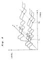
- the noise prediction circuit 11 receives the noise mixed voice input signal that has been transformed to Fourier series, as shown in Fig. 4, in which X-axis represents frequency, Y-axis represents noise level and Z-axis represents time. Noise signal data pl-pi during the predetermined past time is collected in the noise prediction circuit 11, and is evaluated, such as taking an average of pl-pi, to predict a noise signal data pj in the next sampling cycle. Preferably, such a noise signal prediction is carried out for each of the m-channels of the divided bands.
- the noise signal level of the next sampling cycle is predicted using the stored noise signals.
- the predicted noise signal level is sent to a cancellation circuit 12. After that, the predicted noise signal is replaced with the actually detected noise signal and is stored in the storing circuit.
- the storing circuit stores actually detected noise signal at every sampling cycle, and the prediction is effected in predictor by the actually detected noise signal.
- the noise signal level of the next sampling cycle is predicted in the same manner as described above, and is sent to the cancellation circuit 12.
- the predicted noise signal is stored in the storing circuit together with other noise signals obtained previously.
- the actual noise signals of the past data as stored in the storing circuit are sequentially replaced by the predicted noise signals.
- the cancellation circuit 12 is provided to cancel the noise signal in the voice signal by subtracting the predicted noise signal from the Fourier transformed noise mixed voice input signal, and is formed, for example, by a subtractor.
- a combining circuit 13 is provided after the cancellation circuit 12 for combing or synthesizing the m-channel signals to produce a voice signal with the noise signals being canceled not only during the voice signal absent periods, but also during the periods at which the voice signal is present.
- the combing circuit 13 is formed, for example, by an inverse Fourier transformation circuit and a D/A converter.
- signal sl is a noise mixed voice input signal (Fig. 5a) and signal s2 is a signal obtained by Fourier transforming of the input signal sl (Fig. 5b).
- Signal s3 is a predicted noise signal (Fig. 5c) and signal s4 is a signal obtained by canceling the noise signal (Fig. 5d).
- Signal s5 is a signal obtained by inverse Fourier transforming of the noise canceled signal (Fig. 5e).
- the noise-mixed voice signal is divided into a plurality of channels by the band dividing circuit 1, and the divided signals are applied to voice detection circuit 7 and also to the noise prediction circuit 11.
- the voice detection circuit 7 performs cepstrum analysis, as described above, and further detects the peak depending on the cepstrum analysis result.
- the noise prediction circuit 11 predicts the noise signal level of voice portions in each channel.
- the cancellation circuit 12 eliminates the noise signal in each channel using the predicted noise.
- the combining circuit 13 combines the noiseless voice signal in the plurality of channels.
- the coding circuit 6 encodes the combined signal only during the presence of the voice signal in accordance with a coding period control signal.
- the present embodiment further includes circuits 31, 32, 33, and 34, whereby the noise signals are coded separately from the voice signal.
- the noise period detector 31 detects a noise period depending on the voice information detected by the voice detection circuit 7.
- the noise cutout circuit 32 cuts noise signal from the above-mentioned divided signal depending on the resulting noise period information to extract only the noise signal.
- the noise signal joining circuit 33 performs switching operation that connects the extracted noise signal and the predicted noise signal predicted by the noise prediction circuit 11 to produce a continuing noise signal.
- the noise signal coding circuit 34 is circuit for encoding the continuing noise signal.
- the present embodiment allows to obtain coded signal of a continuing noise signal separately from the coded voice signals. For instance, if the voice is a singing voice and the noise signal is of orchestral music played as background, then the singing voice and the background orchestral music can be separated from each other.
- a coding-compression control circuit 40 is further provided after the coding period control circuit 5 for receiving a coding control signal of the voice and producing noise-compression control information. This enables the coding circuit 6 to add the length of the original noise period as information when it compresses the noise periods.
- the voice coding system according to the present invention is adapted to encode only voice portions out of a noise-mixed voice signal and, in turn, compresses noise portions thereof, it is possible to obviate the useless processing of encoding noise signals.
- the data transmission rate can be improved.
- the voice coding system of the present invention can cancel noise signals effectively by predicting the noise signal in the voice signal portions.
Claims (3)
- Nutzsignal-Kodierungssystem, mit:einer Nutzsignalerfassungseinrichtung (1, 7) zum Empfangen eines gemischten Signals aus einem Nutzsignal und einem Hintergrund-Rauschsignal, und zum Erfassen des Vorhandenseins oder Nichtvorhandenseins des in dem gemischten Signal enthaltenen Nutzsignals;einer Nutzsignalperioden-Erfassungseinrichtung (4) zum Erfassen einer Nutzsignalperiode, in welcher das Nutzsignal vorhanden ist;einer Kodierungsperioden-Steuerungseinrichtung (5) zum Erzeugen eines Kodierungsperioden-Steuerungssignals während der Nutzsignalperiode; undeiner Kodiereinrichtung (6) zum Kodieren des gemischten Signals als Reaktion auf das Kodierungsperioden-Steuerungssignal, wodurch das gemischte Signal nur in den Perioden kodiert wird, während derer das Nutzsignal vorhanden ist;wobei das Nutzsignal-Kodierungssystem gekennzeichnet ist durch:eine Rauschvorhersageeinrichtung (11) zum Vorhersagen eines Rauschsignals in dem gemischten Signal durch Bewerten der Rauschsignale, welche in einer vorbestimmten, verstrichenen Zeit erhalten werden;eine Löscheinrichtung (12) zum Subtrahieren des vorhergesagten Rauschsignals von dem gemischten Signal zum Löschen der Rauschsignale in dem gemischten Signal;eine Rauschsignalperioden-Erfassungseinrichtung (31) zum Erfassen einer Rauschsignalperiode, in welcher das Nutzsignal nicht vorhanden ist;eine Kodierungs-Kompressions-Steuerungseinrichtung (40) zum Berechnen der Länge der Rauschsignalperiode aus dem Kodierungsperioden-Steuerungssignal und zum Erzeugen eines kodierten Rauschperioden-Datenwertes, welcher die Zeitlänge der Rauschsignalperiode darstellt, wobei der kodierte Rauschperiodendatenwert in das kodierte Signal eingefügt wird, welches von der Kodiereinrichtung (6) erzeugt wird;eine Rauschextraktionseinrichtung (32) zum Extrahieren des Rauschsignals während der Rauschsignalperiode;eine Rausch-Zusammenfassungseinrichtung (33) zum Ausführen eines Umschaltvorganges zum Verbinden des extrahierten Rauschsignals mit dem vorhergesagten Rauschsignal zum Erzeugen eines kontinuierlichen Rauschsignals; undeine Rauschsignal-Kodiereinrichtung (34) zum Kodieren des kontinuierlichen Rauschsignals.
- Nutzsignal-Kodierungssystem nach Anspruch 1,bei welchem die Nutzsignal-Erfassungseinrichtung (1, 7) umfaßt:eine Bandaufteilungseinrichtung (1) zum Aufteilen des gemischten Signals in mehrere Frequenzbereiche und zum Abgeben der aufgeteilten Signale durch mehrere Kanäle;eine Cepstrum-Analyseeinrichtung zur Cepstrum-Analyse des Signals in jedem Kanal von der Bandaufteilungseinrichtung (1); undeiner Spitzenwerterfassungseinrichtung zum Erfassen eines Cepstrum-Spitzenwertes in dem Cepstrum-Analyse-Ausgangssignal der Cepstrum-Analyseeinrichtung, wodurch ein Nutzsignal als vorhanden erfaßt wird, wenn ein Cepstrum-Spitzenwert erfaßt wird.
- Nutzsignal-Kodierungssystem nach Anspruch 1,
bei welchem das Nutzsignal ein Sprachsignal ist.
Priority Applications (1)
| Application Number | Priority Date | Filing Date | Title |
|---|---|---|---|
| EP96112435A EP0747879B1 (de) | 1990-05-28 | 1991-05-27 | Sprachkodierer |
Applications Claiming Priority (4)
| Application Number | Priority Date | Filing Date | Title |
|---|---|---|---|
| JP138066/90 | 1990-05-28 | ||
| JP138065/90 | 1990-05-28 | ||
| JP13806690 | 1990-05-28 | ||
| JP13806590 | 1990-05-28 |
Related Child Applications (2)
| Application Number | Title | Priority Date | Filing Date |
|---|---|---|---|
| EP96112435A Division EP0747879B1 (de) | 1990-05-28 | 1991-05-27 | Sprachkodierer |
| EP96112435.1 Division-Into | 1996-08-01 |
Publications (2)
| Publication Number | Publication Date |
|---|---|
| EP0459363A1 EP0459363A1 (de) | 1991-12-04 |
| EP0459363B1 true EP0459363B1 (de) | 1997-08-06 |
Family
ID=26471205
Family Applications (2)
| Application Number | Title | Priority Date | Filing Date |
|---|---|---|---|
| EP96112435A Expired - Lifetime EP0747879B1 (de) | 1990-05-28 | 1991-05-27 | Sprachkodierer |
| EP91108612A Expired - Lifetime EP0459363B1 (de) | 1990-05-28 | 1991-05-27 | Sprachkodierer |
Family Applications Before (1)
| Application Number | Title | Priority Date | Filing Date |
|---|---|---|---|
| EP96112435A Expired - Lifetime EP0747879B1 (de) | 1990-05-28 | 1991-05-27 | Sprachkodierer |
Country Status (4)
| Country | Link |
|---|---|
| US (2) | US5293450A (de) |
| EP (2) | EP0747879B1 (de) |
| KR (1) | KR960005741B1 (de) |
| DE (2) | DE69127134T2 (de) |
Families Citing this family (18)
| Publication number | Priority date | Publication date | Assignee | Title |
|---|---|---|---|---|
| FR2687496B1 (fr) * | 1992-02-18 | 1994-04-01 | Alcatel Radiotelephone | Procede de reduction de bruit acoustique dans un signal de parole. |
| FR2697101B1 (fr) * | 1992-10-21 | 1994-11-25 | Sextant Avionique | Procédé de détection de la parole. |
| CA2110090C (en) * | 1992-11-27 | 1998-09-15 | Toshihiro Hayata | Voice encoder |
| WO1995002239A1 (en) * | 1993-07-07 | 1995-01-19 | Picturetel Corporation | Voice-activated automatic gain control |
| US6134521A (en) * | 1994-02-17 | 2000-10-17 | Motorola, Inc. | Method and apparatus for mitigating audio degradation in a communication system |
| TW295747B (de) * | 1994-06-13 | 1997-01-11 | Sony Co Ltd | |
| JPH08102687A (ja) * | 1994-09-29 | 1996-04-16 | Yamaha Corp | 音声送受信方式 |
| US5822726A (en) * | 1995-01-31 | 1998-10-13 | Motorola, Inc. | Speech presence detector based on sparse time-random signal samples |
| GB2312360B (en) * | 1996-04-12 | 2001-01-24 | Olympus Optical Co | Voice signal coding apparatus |
| US6134524A (en) * | 1997-10-24 | 2000-10-17 | Nortel Networks Corporation | Method and apparatus to detect and delimit foreground speech |
| JP4045003B2 (ja) * | 1998-02-16 | 2008-02-13 | 富士通株式会社 | 拡張ステーション及びそのシステム |
| WO2004029935A1 (en) * | 2002-09-24 | 2004-04-08 | Rad Data Communications | A system and method for low bit-rate compression of combined speech and music |
| US7020448B2 (en) * | 2003-03-07 | 2006-03-28 | Conwise Technology Corporation Ltd. | Method for detecting a tone signal through digital signal processing |
| US7903172B2 (en) * | 2005-03-29 | 2011-03-08 | Snell Limited | System and method for video processing |
| CN103200077B (zh) * | 2013-04-15 | 2015-08-26 | 腾讯科技(深圳)有限公司 | 一种语音通话时数据交互的方法、装置及系统 |
| US11138334B1 (en) | 2018-10-17 | 2021-10-05 | Medallia, Inc. | Use of ASR confidence to improve reliability of automatic audio redaction |
| US10872615B1 (en) * | 2019-03-31 | 2020-12-22 | Medallia, Inc. | ASR-enhanced speech compression/archiving |
| US11398239B1 (en) * | 2019-03-31 | 2022-07-26 | Medallia, Inc. | ASR-enhanced speech compression |
Family Cites Families (12)
| Publication number | Priority date | Publication date | Assignee | Title |
|---|---|---|---|---|
| US4053712A (en) * | 1976-08-24 | 1977-10-11 | The United States Of America As Represented By The Secretary Of The Army | Adaptive digital coder and decoder |
| US4550425A (en) * | 1982-09-20 | 1985-10-29 | Sperry Corporation | Speech sampling and companding device |
| US4513426A (en) * | 1982-12-20 | 1985-04-23 | At&T Bell Laboratories | Adaptive differential pulse code modulation |
| EP0140249B1 (de) * | 1983-10-13 | 1988-08-10 | Texas Instruments Incorporated | Sprachanalyse und Synthese mit Energienormalisierung |
| US4696040A (en) * | 1983-10-13 | 1987-09-22 | Texas Instruments Incorporated | Speech analysis/synthesis system with energy normalization and silence suppression |
| US4696039A (en) * | 1983-10-13 | 1987-09-22 | Texas Instruments Incorporated | Speech analysis/synthesis system with silence suppression |
| WO1987000366A1 (en) * | 1985-07-01 | 1987-01-15 | Motorola, Inc. | Noise supression system |
| US4630304A (en) * | 1985-07-01 | 1986-12-16 | Motorola, Inc. | Automatic background noise estimator for a noise suppression system |
| US4920568A (en) * | 1985-07-16 | 1990-04-24 | Sharp Kabushiki Kaisha | Method of distinguishing voice from noise |
| WO1987004294A1 (en) * | 1986-01-06 | 1987-07-16 | Motorola, Inc. | Frame comparison method for word recognition in high noise environments |
| JPH0748695B2 (ja) * | 1986-05-23 | 1995-05-24 | 株式会社日立製作所 | 音声符号化方式 |
| SU1545248A1 (ru) * | 1988-03-11 | 1990-02-23 | Войсковая Часть 25871 | Вокодер |
-
1991
- 1991-05-27 EP EP96112435A patent/EP0747879B1/de not_active Expired - Lifetime
- 1991-05-27 DE DE69127134T patent/DE69127134T2/de not_active Expired - Fee Related
- 1991-05-27 DE DE69133085T patent/DE69133085T2/de not_active Expired - Fee Related
- 1991-05-27 KR KR1019910008653A patent/KR960005741B1/ko not_active IP Right Cessation
- 1991-05-27 EP EP91108612A patent/EP0459363B1/de not_active Expired - Lifetime
- 1991-05-28 US US07/706,575 patent/US5293450A/en not_active Expired - Lifetime
-
1995
- 1995-08-07 US US08/512,077 patent/US5652843A/en not_active Expired - Fee Related
Also Published As
| Publication number | Publication date |
|---|---|
| KR910020645A (ko) | 1991-12-20 |
| US5652843A (en) | 1997-07-29 |
| DE69127134T2 (de) | 1998-02-26 |
| DE69133085D1 (de) | 2002-09-12 |
| US5293450A (en) | 1994-03-08 |
| EP0747879A1 (de) | 1996-12-11 |
| KR960005741B1 (ko) | 1996-05-01 |
| DE69133085T2 (de) | 2003-05-15 |
| EP0459363A1 (de) | 1991-12-04 |
| DE69127134D1 (de) | 1997-09-11 |
| EP0747879B1 (de) | 2002-08-07 |
Similar Documents
| Publication | Publication Date | Title |
|---|---|---|
| EP0459363B1 (de) | Sprachkodierer | |
| US4301329A (en) | Speech analysis and synthesis apparatus | |
| AU739238B2 (en) | Speech coding | |
| US4516259A (en) | Speech analysis-synthesis system | |
| US8473284B2 (en) | Apparatus and method of encoding/decoding voice for selecting quantization/dequantization using characteristics of synthesized voice | |
| US4912764A (en) | Digital speech coder with different excitation types | |
| EP0125423A1 (de) | Vocoder unter Anwendung von Grundfrequenzermittlung auf gefiltertem LPC-Differenzsignal beruhend | |
| KR100269216B1 (ko) | 스펙트로-템포럴 자기상관을 사용한 피치결정시스템 및 방법 | |
| EP1420389A1 (de) | Sprachbandbreitenerweiterungsvorrichtung und -verfahren | |
| EP0275416A1 (de) | Verfahren zur Verbesserung der Qualität kodierter Sprache | |
| JP2707564B2 (ja) | 音声符号化方式 | |
| EP0501421B1 (de) | Sprachkodiersystem | |
| US5884251A (en) | Voice coding and decoding method and device therefor | |
| US4890328A (en) | Voice synthesis utilizing multi-level filter excitation | |
| US4969193A (en) | Method and apparatus for generating a signal transformation and the use thereof in signal processing | |
| US6061648A (en) | Speech coding apparatus and speech decoding apparatus | |
| US4845753A (en) | Pitch detecting device | |
| EP0694907A2 (de) | Sprachkodierer | |
| JP3088204B2 (ja) | コード励振線形予測符号化装置及び復号化装置 | |
| JPH04230799A (ja) | 音声信号符号化装置 | |
| JP2772598B2 (ja) | 音声符号化装置 | |
| EP0212323A2 (de) | Verfahren und Einrichtung von Signalumwandlung und ihre Anwendung zur Signalverarbeitung | |
| JPH0736119B2 (ja) | 区分的最適関数近似方法 | |
| JPH0754438B2 (ja) | 音声処理装置 | |
| EP0662682A2 (de) | Kodierung von Sprachsignalen |
Legal Events
| Date | Code | Title | Description |
|---|---|---|---|
| PUAI | Public reference made under article 153(3) epc to a published international application that has entered the european phase |
Free format text: ORIGINAL CODE: 0009012 |
|
| 17P | Request for examination filed |
Effective date: 19910527 |
|
| AK | Designated contracting states |
Kind code of ref document: A1 Designated state(s): DE FR GB |
|
| 17Q | First examination report despatched |
Effective date: 19941027 |
|
| GRAG | Despatch of communication of intention to grant |
Free format text: ORIGINAL CODE: EPIDOS AGRA |
|
| GRAH | Despatch of communication of intention to grant a patent |
Free format text: ORIGINAL CODE: EPIDOS IGRA |
|
| GRAH | Despatch of communication of intention to grant a patent |
Free format text: ORIGINAL CODE: EPIDOS IGRA |
|
| GRAA | (expected) grant |
Free format text: ORIGINAL CODE: 0009210 |
|
| AK | Designated contracting states |
Kind code of ref document: B1 Designated state(s): DE FR GB |
|
| XX | Miscellaneous (additional remarks) |
Free format text: TEILANMELDUNG 96112435.1 EINGEREICHT AM 01/08/96. |
|
| DX | Miscellaneous (deleted) | ||
| REF | Corresponds to: |
Ref document number: 69127134 Country of ref document: DE Date of ref document: 19970911 |
|
| ET | Fr: translation filed | ||
| PLBE | No opposition filed within time limit |
Free format text: ORIGINAL CODE: 0009261 |
|
| STAA | Information on the status of an ep patent application or granted ep patent |
Free format text: STATUS: NO OPPOSITION FILED WITHIN TIME LIMIT |
|
| 26N | No opposition filed | ||
| REG | Reference to a national code |
Ref country code: GB Ref legal event code: IF02 |
|
| PGFP | Annual fee paid to national office [announced via postgrant information from national office to epo] |
Ref country code: DE Payment date: 20070524 Year of fee payment: 17 |
|
| PGFP | Annual fee paid to national office [announced via postgrant information from national office to epo] |
Ref country code: GB Payment date: 20070523 Year of fee payment: 17 |
|
| PGFP | Annual fee paid to national office [announced via postgrant information from national office to epo] |
Ref country code: FR Payment date: 20070510 Year of fee payment: 17 |
|
| GBPC | Gb: european patent ceased through non-payment of renewal fee |
Effective date: 20080527 |
|
| REG | Reference to a national code |
Ref country code: FR Ref legal event code: ST Effective date: 20090119 |
|
| PG25 | Lapsed in a contracting state [announced via postgrant information from national office to epo] |
Ref country code: FR Free format text: LAPSE BECAUSE OF NON-PAYMENT OF DUE FEES Effective date: 20080602 Ref country code: DE Free format text: LAPSE BECAUSE OF NON-PAYMENT OF DUE FEES Effective date: 20081202 |
|
| PG25 | Lapsed in a contracting state [announced via postgrant information from national office to epo] |
Ref country code: GB Free format text: LAPSE BECAUSE OF NON-PAYMENT OF DUE FEES Effective date: 20080527 |