EP0459350A2 - Method of and apparatus for generating image data representing integrated image - Google Patents
Method of and apparatus for generating image data representing integrated image Download PDFInfo
- Publication number
- EP0459350A2 EP0459350A2 EP91108577A EP91108577A EP0459350A2 EP 0459350 A2 EP0459350 A2 EP 0459350A2 EP 91108577 A EP91108577 A EP 91108577A EP 91108577 A EP91108577 A EP 91108577A EP 0459350 A2 EP0459350 A2 EP 0459350A2
- Authority
- EP
- European Patent Office
- Prior art keywords
- image
- data
- integrated
- image data
- elements
- Prior art date
- Legal status (The legal status is an assumption and is not a legal conclusion. Google has not performed a legal analysis and makes no representation as to the accuracy of the status listed.)
- Granted
Links
Images


Classifications
-
- G—PHYSICS
- G06—COMPUTING; CALCULATING OR COUNTING
- G06T—IMAGE DATA PROCESSING OR GENERATION, IN GENERAL
- G06T11/00—2D [Two Dimensional] image generation
- G06T11/60—Editing figures and text; Combining figures or text
-
- H—ELECTRICITY
- H04—ELECTRIC COMMUNICATION TECHNIQUE
- H04N—PICTORIAL COMMUNICATION, e.g. TELEVISION
- H04N1/00—Scanning, transmission or reproduction of documents or the like, e.g. facsimile transmission; Details thereof
- H04N1/387—Composing, repositioning or otherwise geometrically modifying originals
- H04N1/3871—Composing, repositioning or otherwise geometrically modifying originals the composed originals being of different kinds, e.g. low- and high-resolution originals
Definitions
- the present invention relates to a method and an apparatus for generating an image data representing an integrated image, and more paticularly, to an improvement in integrating respective images of a character, diagram and a picture to generate a halftone dot image data or a binary image data of an integrated image and deliver the same to an output device such as an image scanner.
- Page description language is a language for describing shapes, colors and locations of the characters, diagrams and pictures in accordance with a specific program grammar and an example thereof is a language "Post Script”.
- a program described in a page description language is called "image description program” hereinafter.
- Fig. 6 is a block diagram showing an image processing system for generating an image in accordance with an image description program.
- the image processing system comprises a host processor 10, an image integrating device 20 and an output device 30.
- the host processor 10 receives an image description program P i , a multi-tone image data D i expressing an multi-tone image of a picture and the like through an external interface 13 from an external device (not shown) and decodes the image description program P i to produce vector data V l and V f expressing characters and diagrams, respectively.
- a character font disc 11 for storing character fonts and an image data memory 12 for temporarily storing a multi-tone image data are connected to the host processor 10.
- the vector data V l and V f and the multi-tone image data D i are transmitted from the host processor 10 to an data management unit 21 in the image integrating device 20.
- the data management unit 21 has a function to control the whole operation of the image integrating device 20.
- the vector data V l and V f and the multi-tone image data D i are delivered from the data management unit 21 to the data processing unit 22.
- the data processing unit 22 performs a coordinate transformation with regard to these data, and additionally, it transforms the vector data V l and V f into a raster data R l and R f , respectively.
- the raster data R l and R f and the multi-tone image data D ia obtained in the data processing unit 22 are supplied to a dot generator (a halftone dot image genarating unit) 23 and transformed into a halftone image data D h .
- a dot generator a halftone dot image genarating unit
- the halftone dot image data D h expresses respective ON/OFF states of halftone dots, in which a single bit is asssigned to each dot cell in each color component.
- the "dot cell” is respective ones of unit areas forming one halftone dot and the color component is respective ones of R (red), G (green) and B (blue), for example.
- the halftone dot data D h is temporarily stored in an output frame memory 24 in which 1 bit is assigned to each dot cell in each color component, and thereafter, it is outputted to an output device 30 to display or record an integrated halftone dot image.
- the character raster data R l , the diagram raster data R f and the multi-tone image data D ia are separately applied to the dot generator 23, and then a data processing to produce the halftone dot data D h is performed. For this reason, all of the data R l , R f and D ia are processed under the common condition where resolution is set at the highest resolution in respective data R l , R f and D ia and number of gradartion levels is set at the maximum number of gradation levels in respective data R l , R f and D ia .
- the maximum number of gradation levels is the maximun one of respective numbers of bits expressing optical density levels in the data R l , R f and D ia , for example.
- an efficiency of processing the image data is not necessarily high and there arises the problem that the processing is slow or an efficiency in using an output frame memory is low.
- the dot generator 23 generates the halftone dot data D h by comparing optical density levels of the pixels expressed by the data R l , R f and D ia , respectively, with threshold values or screen pattern data for each pixel in each scanning line.
- the screen pattern data is previously stored in the dot generator 23.
- regions to which characters, diagrams and pictures to be allocated on an imaging plane are often not rectangular.
- the head coordinates on an image plane in respective main scanning lines in the region is transformed into addresses of the screen pattern data or coordinates on a screen pattern plane, and the screen pattern data is read in accordance with the address.
- Such a transformation processing is a very complex one, and thus, there arises the problem that a processing speed is lowered in the dot generator 23.
- the present invention is directed to a method of generating an integrated image including a plural types of image elements.
- the method comprises the steps of: (a) obtaining respective image data representing respective image elements in respective resolutions and in respective data length for each pixel; (b) designating positions of the image elements on an image plane on which an integrated image is to be defined; (c) dividing the image plane into a plurality of regions; (d) selecting one of the plurality of regions to obtain a selected region; (e) determining what image elements are included in the selected region, to thereby specify objective image elements; (f) determining maximum resolution and maximum data length within respective resolutions and data length of the objective image elements; (g) integrating on the selected region the objective image elements in the maximum resolution and in the maximum data length to obtain a part of an integrated image data representing a part of the integrated image defined on the selected region; and (h) repeating the steps (d) through (g) while serially changing the selected region within the plurality of regions, to thereby obtain the integrated image data representing the whole of the integrated image on the image plane.
- the method further comprising the step of: (i) prior to the step (a), determining a plurality of image-integration modes characterized by different resolutions and different data length.
- the step (g) comprises the steps of: (g-1) selecting one of the plurality of image-integration modes in accordance with the maximum resolution and the maximum data length, to thereby specify a selected image-integration mode; and (g-2) integrating on the selected region the objective image elements in the selected image-integration mode to obtain the part of the integrated image data.
- the image elements may be classified into a plurality of image types including multi-tone image type and binary image type.
- the plurality of image-integration modes may include first through thirdimage-integration modes.
- the first image-integration mode is characterized by relatively high resolution and relatively small data length for each pixel, while the second image-integration mode is characterized by relatively low resolution and relatively large data length for each pixel.
- the third image-integration mode characterized by relatively high resolution and relatively large data length for each pixel.
- the present invention is also directed to an apparatus for generating an integrated image including a plural types of image elements.
- the apparatus comprises: (a) means for inputting: respective image data representing image elements in respective resolutions and in respective data length for each pixel; and positions of the image elements on an image plane on which an integrated image is to be defined; (b) means for dividing the image plane into a plurality of regions; (c) means for serially selecting one of the plurality of regions to obtain a selected region; (d) means for determining what image elements are included in the selected region, to thereby specify objective image elements; (e) means for determining maximum resolution and maximum data length within respective resolutions and data length of the objective image elements; (f) processor means for integrating on the selected region the objective image elements in the maximum resolution and in the maximum data length to obtain a part of an integrated image data representing a part of the integrated image defined on the selected region; (g) memory means for storing respective parts of an integrated image data; and (h) means for reading the respective parts of anintegrated image data out of the memory means to output the respective parts of the integrated image data.
- the memory means may include a plurality of image frame memories used for storing respective parts of the integrated image data obtained through different iamge-integration modes.
- an object of the present invention to generate an integrated image of characters, diagrams and pictures at a high efficiency.
- Another object of the present invention is to generate a halftone dot image without a complex transformation processing of coordinates in a dot generator even if respective image regions are not rectangular.
- Fig. 1 is a block diagram showing an image processing system comprising an image integrating device 200 according to a preferred embodiment of the present invention.
- the image processing system has a host processor 10, a character font disc 11, an image data memory 12 and an output device 30.
- the image integrating device 200 has a data management unit 21, an image processing unit 220, a dot generator 23 and an output frame memory 24.
- the image processing unit 220 has three image processing modules 220a through 220c. Furthermore, the image processing modules 220a through 220c have data processing units 22a through 22c and image frame memories 25a through 25c, respectively.
- the image frame memories 25a through 25c are elements characterizing the present invention.
- the capacity of each memory 25a, 25b, 25c is represnted by a symbol A t (not shown in the drawings). Details of the memories 25a-25c will be described later.
- the host processor 10 As the host processor 10, a so-called engineering work station and a personal computer may be employed.
- the image description program P i represents characters and diagrams, while the multi-tone image data D i represents multi-tone pictures. Respective positions of the characters, the diagrams and the pictures on an image plane may be designated in the image description program P i and the multi-tone image data D i , or alternatively, they may be designated by inputting another data defining them.
- the characters, the diagrams and the pictures are image elements to be integrated on the image plane.
- the host processor 10 decodes the image description program P i to obtain a character vector data V l and a diagram vector data V f and temporarily stores multi-tone image data D i in the image data memory 12. Characters in the image description program P i are designated in the form of character font codes, and therefore, the host processor 10 produces the character vector data V l based upon vector data of character fonts stored in the character font disc 11 and the character font codes in the image descriving program P i .
- the character vector data V l , the diagram vector data V f and the multi-tone image data D i are transmitted from the host processor 10 to the data management unit 21 in the image integrating device 200.
- the data management unit 21 divides an image plane into a plurality of areas based upon these data.
- Fig. 2 conceptionally shows images on the image plane IP, which images are expressed by the image description program P i and the multi-tone image data D i .
- the image plane IP there are five regions A1 through A5 in which characters, diagrams or patterns are arranged. In all of them, the regions A1 and A3 contain characters only, while the regions A2 and A5 contain photographs of pictures only.
- the region A4 contains diagrams only.
- squares (A1, A3) show regions of characters
- elipses (A2, A5) show regions of pictures
- a parallelogram (A4) shows a region of a diagram or a line drawing.
- the image plane IP is divided into equal rectangular strip regions R1 through R11. As described later, each strip region has a predetermined dimensions and the image processing unit 220 executes an image processing to each of the strip regions R1 through R11.
- characters and diagrams can be expressed by binary data, and they are expressed at a high resolution (e.g., 1500 dpi) to reproduce their shapes clearly.
- patterns are expressed by multivalued data (8 bit data in this preferred emobodiment), and they are generally expressed with low resolution (e.g., 300 dpi). Then, the data management unit 21 judges which mode in the following three modes images in each strip region should be processed in.
- the procedures for processing images in a selected one of these modes are previously stored in the data management unit 21 in the form of software programs.
- images of characters and diagrams are represented in the form of binary monochrome images in many cases, they may be represented in the form of multi-tone images in which one or more arbitrary colors are designated. Such a multivalued image is processed in the Mode 3 even if it is an image including characters and/or diagrams only.
- Figs. 3(a) through 3(c) are diagrams showing a concept of the image data for each pixel in the Modes 1 through 3, respectively.
- the hights of rectangular poles in Figs. 3(a) through 3(c) show the numbers of bits in the image data for each pixel, while widths of their bottoms and tops show dimensions of a single pixel. Since the size of a single pixel is 1500 dpi in the Modes 1 and 3, the width of the bottom of each rectangular pole is about 17 ⁇ m. On the other hand, since a single pixel is 300 dpi in the Mode 2, the width of the bottom of the pole is about 85 ⁇ m.
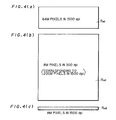
- Figs. 4(a) through 4(c) are diagrams relatively showing the dimensions of image areas which can be stored in each image frame memory 25a, 25b, 25c of 8M bite under respective modes.
- the image region R m2 has an area equal to that of a region including 200 M pixels of 1500 dpi.
- each frame memory 25a, 25b, 25c can store image data of an image region R m3 including 8 M pixels of 1500 dpi.
- the area rate of the three image regions R m1 through R m3 is 8 : 25 : 1.
- the image region R m3 which can be stored in each frame memory 25a, 25b, 25ca in the Mode 3 is dimensionally smallest in the image regions R m1 through R m3 in the modes 1 through 3, which is 1/8 of the image region R m1 in the Mode 1 and 1/25 of the image region R m2 in the Mode 2.
- Areas of the strip regions R1 through R11 shown in Fig. 2 are set equal to an area of the image region R m3 in Figs.
- the data management unit 21 determines a processing mode among the Modes 1 through 3 so that an integrated image is generated in the image frame memory in accordance with the highest resolution and the largest number of bits in the image data of images contained in the strip regions R1 through R11.
- the image data for the strip regions R1 through R3, R7 and R8 are processed in the Mode 1.
- the strip regions R4 and R11 are processed in the Mode 2, while the strip regions R5, R6, R9 and R10 are processed in the Mode 3.
- the image frame memories 25a-25c are prepared so that arbitrary one of various integrated images can be written in a corresponding image frame memory.
- the image processing unit 220 After the determination of the mode of each strip region in the data management unit 21 is completed, the image processing unit 220 generates respective parts of an integrated image in the syrip regions R1 through R11 based upon the character vector data V l , the diagram vector data V f and the multi-tone image data D i in accordance with instructions of the data management unit 21 in the following manner and stores the same in the image frame memories 25a through 25c.
- the character vector data V l in the strip region R1 is supplied from the data management unit 21 to the image processing unit 220.
- the character vector data V l is processed in the data processing unit 22a of the image processing module 220a.
- the data processing units 22a through 22c are so-called second generation graphic controller LSIs, which perform a coordinate transformation processing, such as an enlargement, reduction, rotation and the like, to the vector data V l and V f and the multi-tone image data D i and has a function to transform the vector data V l and V f into raster data R l and R f .
- the part of the integrated image on the strip region R1 is generated on the basis of the raster data R l and R f and a multi-tone image data D ia after the transformation, and stors or draws the same in the image frame memory 25a. Since the strip region R1 contains characters only, the image drawing is done based simply upon the character raster data R l . Since the strip region R1 is processed in accordance with the Mode 1, the image frame memory 25a is used as a frame memory of 64M pixels x 1 bit, where each one pixel corresponds to 1500 dpi. The strip regions R2 and R3 as well as the strip region R1 are processed in accordance with the Mode 1. As previously mentioned, image data on eight of the strip regions obtained through the processing of Mode 1 can be stored in one image frame memory at a time. Therefore, the image data in the strip regions R1 through R3 can be stored in the image frame memory 25a at a time.
- the strip region R4 is processed in the Mode 2 because it includes pictures only.
- the Mode 2 for the strip region R4 is different from the Mode 1 for the strip regions R1 through R3 , and therefore, as shown in Fig. 2, an image data in the strip R4 is stored in the next image frame memory 25b.
- the multi-tone image data D ia in the strip region R4 is applied to the data processing unit 22b of the image processing module 220b for coordinate transformation and thereafter is stored in the image frame memory 25b.
- an image processing module for storing the image part obtained is also changed, whereby images of different modes cannot exist in any one of image frame memories 25a-25c.
- the strip region R5 includes characters and pictures.
- the data management unit 21 detects that the rectangle region R5 includes characters and pictures and decides to process the data thereof in the Mode 3.
- This processing mode (Mode 3) is different from the processing mode (Mode 2) for the prior strip region R4, and hence, the character vector data V l and the multi-tone image data D i in the strip region R5 are processed by the third data processing module 220c.
- the data processing unit 22c in the data processing module 220c processes the character vector data V l and the multi-tone image data D i in the strip region R5 and draws the part of the integrated image in the image frame memory 25c.
- the image memory 25a is used as a frame memory of 8M pixels x 8 bit, in which each pixel corresponds to 1500 dpi.
- the data processing unit 22c integrates respective images of the character and the the picture in the strip region R5 and stores an image data of the integrated image in the image frame memory 25c.
- a data in a part where a character (or a diagram) in the character image (or a diagram image) should be solid or filled is provided with the maximum value "255" within values that can be expressed with 8 bit, while a data in a part where it should keep blank is provided with the minimum value "0".
- the strip region R6, similar to the strip region R5, is processed in the Mode 3.
- the data processing unit 22a since the image frame memory 25c is full of image data of the strip region R5, the data processing unit 22a in turn performs a processing For the region R6. That is, the data processing unit 22a integrates images of characters and patterns, and an image data of the integrated image thus obtained is stored in the image frame memory 25a.
- the image data in the strip regions R1 through R3 is read from the image frame memory 25a and converted into halftone dots in the dot generator 23.
- the image processing modules 220a through 220c includng the image frame memories 25a through 25c, respectively are cyclically employed for generating respective parts of the integrated image in the strip regions R1 through R11 on the image plane IP. Shift from one image frame memory to another image frame memory for storing a part of the integrated image newly generated is carried out every time when the one image frame memory is full of image data as shown in the above and every time when the mode in the generation of the integrated image is changed from one strip region to the next strip region.
- the image data for the other other strip regions R7 through R11 are generated similar to the above. That is, the image data for the strip regions R7 and R8 are processed in the Mode 1 and stored in the image frame memory 25b.
- the strip regions R9 and R10 are processed in the Mode 3 while the strip region R11 is processed in the Mode 2, and their respective image data are stored in the image frame memories 25c, 25a and 25b, respectively.
- the image data D p of each pixel in each strip region is temporarily stored in corresponding one of the image frame memories 25a through 25c and is transmitted to the dot generator or halftone dot generating unit 23.
- the image data D p stored in the image frame memories 25a through 25c are those for the image plane including areas where no character, no diagram and no pattern is provided, i.e., areas other than regions A1 through A5 shown in Fig. 2.
- the image data D p is serially read out from the head coordinate Ymin to the end cooridnate Ymax on each scanning line along a main scanning direction Y, while selection of scanning lines is serially conducted in respective strip regions along a subscanning diection Y.
- the dot generator 23 compares the image data with threshold values to generate a halftone dot image data (binarized image data) D h expressing a binary brightness level or ON/OFF of each pixel in 1 bit.
- the size of respective pixels is determined in accordance with resolution (e.g., 1500 dpi) in an output device 30.
- the output device 30 is an image scanner
- the resolution in the output device 30 corresponds to the recording resolution of light beams provided for exposing a photosensitive material.
- the halftone dot image data D h has a data structure corresponding to a screen whose line density is selected from the range 65 per inch to 175 per inch and whose screen angle is 0°, 15°, 45° or 75°, for example.
- the dot generator 23 is not a simple dot generator but an improved one which is operable to descriminate respective modes assigned for the strip regions R1-R11, and changes the type of the data conversion. Details of the generation are as follows:
- the image data D p applied from the image frame memory 25a through 25c to the dot generator 23 is expressed in 1 bit for each pixel corresponding to 1500 dpi.
- the pixel size in the image data D p is the same as the size of recording pixels, and the image data D p is transmitted to the output frame memory 24 as the halftone dot image data D p without substantial processing in the dot generator 23.
- the image data D p is compared with the threshold values representing screen pattern to genatate the halftone dot image data D h .
- the threshold values or screen pattern data are previously stored in a screen pattern memory SPM (not shown) and are read from the SPM in the serial order of scanning lines in accordance with the condition that the image data D p is read from the image frame memory in the order of scanning lines.
- Distribution of the threshold values in each halftone dot area and the structure for comparing image data with the same are well-known in the art, and are disclosed in Japanese Patent Laid-Open Gazette No. 63-212273 (1988), for example.
- the image data D p is expressed in 8 bit, and each pixel corresponds to 1500 dpi.
- the image data D p is directly compared with the threshold values or screen pattern data, whereby the halftone dot image data D h is genarated.
- the halftone dot image D h generated in the dot generator 23 is temporarily stored in the output frame memory 24 and then outputted to the output device 30 to record a halftone dot integrated image.
- the output frame memory 24 has a capacity of 64 MB, for example, and is capable of storing the halftone dot image data D h for the image plane PL.
- the output device 30 may be a drum-type output scanner, and a halftone dot image is recorded as a latent image on a photosensitive film.
- a processing mode of each strip region is determined in accordance with the type of image elements (characters, diagrams, pictures, etc.) included in each of strip regions, and the type of process in generating respective parts of an integrated image and in storing the same in the image frame memories 25a through 25c is changed in accordance with the modegiven to each strip region. Therefore, there is an advantage that the image frame memories can be efficiently used. This advantage can be more clearly understtod, compared with the case where all strip regions are processed in the Mode 3 and all the image frame memories are used in agreement with the Mode 3.
- the size of a region which can be stored in one image frame memory is only 1/8 of that when the strip region is processed in the Mode 1.
- an image of a region eight times as large as an image in the above-indicated reference case can be stored in each image frame memory.
Abstract
Description
- The present invention relates to a method and an apparatus for generating an image data representing an integrated image, and more paticularly, to an improvement in integrating respective images of a character, diagram and a picture to generate a halftone dot image data or a binary image data of an integrated image and deliver the same to an output device such as an image scanner. Description of the Background Art
- Some of current personal computers and work stations are capable of generating an image including characters, diagrams and pictures and transforming the image into a page description language. Such an image is called "integrated image". Page description language is a language for describing shapes, colors and locations of the characters, diagrams and pictures in accordance with a specific program grammar and an example thereof is a language "Post Script". A program described in a page description language is called "image description program" hereinafter.
- Fig. 6 is a block diagram showing an image processing system for generating an image in accordance with an image description program. The image processing system comprises a
host processor 10, animage integrating device 20 and anoutput device 30. - The
host processor 10 receives an image description program Pi, a multi-tone image data Di expressing an multi-tone image of a picture and the like through anexternal interface 13 from an external device (not shown) and decodes the image description program Pi to produce vector data Vℓ and Vf expressing characters and diagrams, respectively. To thehost processor 10, acharacter font disc 11 for storing character fonts and animage data memory 12 for temporarily storing a multi-tone image data are connected. - The vector data Vℓ and Vf and the multi-tone image data Di are transmitted from the
host processor 10 to andata management unit 21 in theimage integrating device 20. Thedata management unit 21 has a function to control the whole operation of theimage integrating device 20. - The vector data Vℓ and Vf and the multi-tone image data Di are delivered from the
data management unit 21 to thedata processing unit 22. Thedata processing unit 22 performs a coordinate transformation with regard to these data, and additionally, it transforms the vector data Vℓ and Vf into a raster data Rℓ and Rf, respectively. The raster data Rℓ and Rf and the multi-tone image data Dia obtained in thedata processing unit 22 are supplied to a dot generator (a halftone dot image genarating unit) 23 and transformed into a halftone image data Dh. The halftone dot image data Dh expresses respective ON/OFF states of halftone dots, in which a single bit is asssigned to each dot cell in each color component. The "dot cell" is respective ones of unit areas forming one halftone dot and the color component is respective ones of R (red), G (green) and B (blue), for example. - The halftone dot data Dh is temporarily stored in an
output frame memory 24 in which 1 bit is assigned to each dot cell in each color component, and thereafter, it is outputted to anoutput device 30 to display or record an integrated halftone dot image. - In the conventional
image integrating device 20, the character raster data Rℓ, the diagram raster data Rf and the multi-tone image data Dia are separately applied to thedot generator 23, and then a data processing to produce the halftone dot data Dh is performed. For this reason, all of the data Rℓ, Rf and Dia are processed under the common condition where resolution is set at the highest resolution in respective data Rℓ, Rf and Dia and number of gradartion levels is set at the maximum number of gradation levels in respective data Rℓ, Rf and Dia. The maximum number of gradation levels is the maximun one of respective numbers of bits expressing optical density levels in the data Rℓ, Rf and Dia, for example. - Thus, an efficiency of processing the image data is not necessarily high and there arises the problem that the processing is slow or an efficiency in using an output frame memory is low.
- The
dot generator 23 generates the halftone dot data Dh by comparing optical density levels of the pixels expressed by the data Rℓ, Rf and Dia, respectively, with threshold values or screen pattern data for each pixel in each scanning line. The screen pattern data is previously stored in thedot generator 23. Now then, regions to which characters, diagrams and pictures to be allocated on an imaging plane are often not rectangular. In the prior art, in order to produce a halftone dot data on a region that is not rectangular, it is requred that the head coordinates on an image plane in respective main scanning lines in the region is transformed into addresses of the screen pattern data or coordinates on a screen pattern plane, and the screen pattern data is read in accordance with the address. Such a transformation processing is a very complex one, and thus, there arises the problem that a processing speed is lowered in thedot generator 23. - The present invention is directed to a method of generating an integrated image including a plural types of image elements.
- According to the present invention, the method comprises the steps of: (a) obtaining respective image data representing respective image elements in respective resolutions and in respective data length for each pixel; (b) designating positions of the image elements on an image plane on which an integrated image is to be defined; (c) dividing the image plane into a plurality of regions; (d) selecting one of the plurality of regions to obtain a selected region; (e) determining what image elements are included in the selected region, to thereby specify objective image elements; (f) determining maximum resolution and maximum data length within respective resolutions and data length of the objective image elements; (g) integrating on the selected region the objective image elements in the maximum resolution and in the maximum data length to obtain a part of an integrated image data representing a part of the integrated image defined on the selected region; and (h) repeating the steps (d) through (g) while serially changing the selected region within the plurality of regions, to thereby obtain the integrated image data representing the whole of the integrated image on the image plane.
- Preferably, the method further comprising the step of: (i) prior to the step (a), determining a plurality of image-integration modes characterized by different resolutions and different data length.
- In accordance with the step (i), the step (g) comprises the steps of: (g-1) selecting one of the plurality of image-integration modes in accordance with the maximum resolution and the maximum data length, to thereby specify a selected image-integration mode; and (g-2) integrating on the selected region the objective image elements in the selected image-integration mode to obtain the part of the integrated image data.
- The image elements may be classified into a plurality of image types including multi-tone image type and binary image type.
- The plurality of image-integration modes may include first through thirdimage-integration modes. The first image-integration mode is characterized by relatively high resolution and relatively small data length for each pixel, while the second image-integration mode is characterized by relatively low resolution and relatively large data length for each pixel. Further, the third image-integration mode characterized by relatively high resolution and relatively large data length for each pixel.
- The present invention is also directed to an apparatus for generating an integrated image including a plural types of image elements.
- According to the present invention, the apparatus comprises: (a) means for inputting: respective image data representing image elements in respective resolutions and in respective data length for each pixel; and positions of the image elements on an image plane on which an integrated image is to be defined; (b) means for dividing the image plane into a plurality of regions; (c) means for serially selecting one of the plurality of regions to obtain a selected region; (d) means for determining what image elements are included in the selected region, to thereby specify objective image elements; (e) means for determining maximum resolution and maximum data length within respective resolutions and data length of the objective image elements; (f) processor means for integrating on the selected region the objective image elements in the maximum resolution and in the maximum data length to obtain a part of an integrated image data representing a part of the integrated image defined on the selected region; (g) memory means for storing respective parts of an integrated image data; and (h) means for reading the respective parts of anintegrated image data out of the memory means to output the respective parts of the integrated image data.
- The memory means may include a plurality of image frame memories used for storing respective parts of the integrated image data obtained through different iamge-integration modes.
- Since image-integration on respective regions on the image plane are carried out in respective optimum modes, the efficiency in the image-integration is improved.
- Accordingly, an object of the present invention to generate an integrated image of characters, diagrams and pictures at a high efficiency.
- Another object of the present invention is to generate a halftone dot image without a complex transformation processing of coordinates in a dot generator even if respective image regions are not rectangular.
- These and other objects, features, aspects and advantages of the present invention will become more apparent from the following detailed description of the present invention when taken in conjunction with the accompanying drawings.
-
- Fig. 1 is a block diagram showing an image processing system comprising an image integrating device according to a preferred embodiment of the present invention;
- Figs. 2 and 5 are conceptual diagrams showing a method of dividing a halftonne dot image;
- Figs. 3(a) through 3(c) are conceptual diagrams showing the size of a pixel and the data length of an image data for one pixel in respective processing modes;
- Figs. 4(a) through 4(c) are diagrams showing the dimensions of an image which can be accommodated in a single image frame memory in respective processing modes; and
- Fig. 6 is a block diagram showing a conventional image processing system.
- Fig. 1 is a block diagram showing an image processing system comprising an
image integrating device 200 according to a preferred embodiment of the present invention. In addition to theimage integrating device 200, the image processing system has ahost processor 10, acharacter font disc 11, animage data memory 12 and anoutput device 30. - The
image integrating device 200 has adata management unit 21, animage processing unit 220, adot generator 23 and anoutput frame memory 24. Theimage processing unit 220 has threeimage processing modules 220a through 220c. Furthermore, theimage processing modules 220a through 220c havedata processing units 22a through 22c andimage frame memories 25a through 25c, respectively. - In those components, the
image frame memories 25a through 25c are elements characterizing the present invention. Theimage frame memories 25a through 25c are memories for storing image data of binary high resolution image and a multivalued high resolution image in accordance with a selected mode mentioned later, each of which memories has a capacity of 8 MB (mega bites) or 8x8=64 mega bits, for example. The capacity of eachmemory memories 25a-25c will be described later. - As the
host processor 10, a so-called engineering work station and a personal computer may be employed. Thehost processor 10, as in the prior art, reveives an image description program Pi and multi-tone image data Di from an external device through anexternal interface 13. The image description program Pi represents characters and diagrams, while the multi-tone image data Di represents multi-tone pictures. Respective positions of the characters, the diagrams and the pictures on an image plane may be designated in the image description program Pi and the multi-tone image data Di, or alternatively, they may be designated by inputting another data defining them. The characters, the diagrams and the pictures are image elements to be integrated on the image plane. - The
host processor 10 decodes the image description program Pi to obtain a character vector data Vℓ and a diagram vector data Vf and temporarily stores multi-tone image data Di in theimage data memory 12. Characters in the image description program Pi are designated in the form of character font codes, and therefore, thehost processor 10 produces the character vector data Vℓ based upon vector data of character fonts stored in thecharacter font disc 11 and the character font codes in the image descriving program Pi. - The character vector data Vℓ, the diagram vector data Vf and the multi-tone image data Di are transmitted from the
host processor 10 to thedata management unit 21 in theimage integrating device 200. Thedata management unit 21 divides an image plane into a plurality of areas based upon these data. - Fig. 2 conceptionally shows images on the image plane IP, which images are expressed by the image description program Pi and the multi-tone image data Di. In the image plane IP, there are five regions A₁ through A₅ in which characters, diagrams or patterns are arranged. In all of them, the regions A₁ and A₃ contain characters only, while the regions A₂ and A₅ contain photographs of pictures only. The region A₄ contains diagrams only. In Fig. 2, squares (A₁, A₃) show regions of characters, elipses (A₂, A₅) show regions of pictures, and a parallelogram (A₄) shows a region of a diagram or a line drawing. On the other hand, the image plane IP is divided into equal rectangular strip regions R₁ through R₁₁. As described later, each strip region has a predetermined dimensions and the
image processing unit 220 executes an image processing to each of the strip regions R₁ through R₁₁. - Ordinarily, characters and diagrams (line drawings) can be expressed by binary data, and they are expressed at a high resolution (e.g., 1500 dpi) to reproduce their shapes clearly. On the other hand, patterns are expressed by multivalued data (8 bit data in this preferred emobodiment), and they are generally expressed with low resolution (e.g., 300 dpi). Then, the
data management unit 21 judges which mode in the following three modes images in each strip region should be processed in. - (I) Mode 1: A mode for processing a binary high resolution image data of an image including characters and/or diagrams (line drawings) only. In this
Mode 1, the size of each pixel is 1500 dpi (dots per inch) and the image data for each pixel is represented by 1 bit. Theimage frame memory - (II) Mode 2: A mode for processing a multivalued low resolution image data of an image including patterns only. The size of each pixel is 300 dpi and the image data for each pixel is represented by 8 bit. The
image frame memory - (III) Mode 3: A mode for processing a multivalued high resolution image data of an image including characters and/or diagrams as well as patterns. The size of each pixel is 1500 dpi and the image data for each pixel is represented by 8 bit. The
image frame memory - The procedures for processing images in a selected one of these modes are previously stored in the
data management unit 21 in the form of software programs. - In genaral, when the symbols Pj, Nj and Sj (j= 1,2,3) are introduced in accordance with the following definition (i) through (iii), these values Pj, Nj and Sj are so selected that the following expressions (1) through (4) are held.
- (i) Pj: the number of pixels storing in the iamge flame memory:
- (ii) Nj: the data length or the number of bits in representing each pixel;
- (iii) Sj: resolution in bpi.


- Preferably, the values Pj, Nj and Sj (j= 1,2,3) are so selected that the following expressions (5) is held in place of the expression (1).

- In the preferred embodiment, values Nc, Nd, Np, Sc' Sd and Sp are defined in the expressions (6) through (11) and the values Pj, Nj and Sj (j= 1,2,3) are determined in the following expressions (12) through (20), as understood from the above-indicated definition (I), (II) and (III) of the Modes 1-3.


- Although images of characters and diagrams are represented in the form of binary monochrome images in many cases, they may be represented in the form of multi-tone images in which one or more arbitrary colors are designated. Such a multivalued image is processed in the
Mode 3 even if it is an image including characters and/or diagrams only. - Figs. 3(a) through 3(c) are diagrams showing a concept of the image data for each pixel in the
Modes 1 through 3, respectively. The hights of rectangular poles in Figs. 3(a) through 3(c) show the numbers of bits in the image data for each pixel, while widths of their bottoms and tops show dimensions of a single pixel. Since the size of a single pixel is 1500 dpi in theModes Mode 2, the width of the bottom of the pole is about 85 µm. - Figs. 4(a) through 4(c) are diagrams relatively showing the dimensions of image areas which can be stored in each
image frame memory Mode 1, eachframe memory Mode 2, eachframe memory Mode 3, eachframe memory frame memory Mode 3 is dimensionally smallest in the image regions Rm1 through Rm3 in themodes 1 through 3, which is 1/8 of the image region Rm1 in theMode Mode 2. Areas of the strip regions R₁ through R₁₁ shown in Fig. 2 are set equal to an area of the image region Rm3 in Figs. 4(a) through 4(c). In this way, when a strip region including picrures as well as character and/or diagrams is processed in theMode 3, the image data of the strip region can be stored in one of theimage frame memories 25a-25c. Eight of strip regions including characters and/or diagrams but no pictues can be stored in one of theimage frame memories 25a-25c at a time. Furthermore, twenty-five of strip regions including pictures only can be stored in one of theimage frame memories 25a-25c at a time. - The
data management unit 21 determines a processing mode among theModes 1 through 3 so that an integrated image is generated in the image frame memory in accordance with the highest resolution and the largest number of bits in the image data of images contained in the strip regions R₁ through R₁₁. The image data for the strip regions R₁ through R₃, R₇ and R₈ are processed in theMode 1. The strip regions R₄ and R₁₁ are processed in theMode 2, while the strip regions R₅, R₆, R₉ and R₁₀ are processed in theMode 3. - The
image frame memories 25a-25c are prepared so that arbitrary one of various integrated images can be written in a corresponding image frame memory. - After the determination of the mode of each strip region in the
data management unit 21 is completed, theimage processing unit 220 generates respective parts of an integrated image in the syrip regions R₁ through R₁₁ based upon the character vector data Vℓ, the diagram vector data Vf and the multi-tone image data Di in accordance with instructions of thedata management unit 21 in the following manner and stores the same in theimage frame memories 25a through 25c. - The character vector data Vℓ in the strip region R₁ is supplied from the
data management unit 21 to theimage processing unit 220. The character vector data Vℓ is processed in thedata processing unit 22a of theimage processing module 220a. Thedata processing units 22a through 22c are so-called second generation graphic controller LSIs, which perform a coordinate transformation processing, such as an enlargement, reduction, rotation and the like, to the vector data Vℓ and Vf and the multi-tone image data Di and has a function to transform the vector data Vℓ and Vf into raster data Rℓ and Rf. - Furthermore, the part of the integrated image on the strip region R₁ is generated on the basis of the raster data Rℓ and Rf and a multi-tone image data Dia after the transformation, and stors or draws the same in the
image frame memory 25a. Since the strip region R₁ contains characters only, the image drawing is done based simply upon the character raster data Rℓ. Since the strip region R₁ is processed in accordance with theMode 1, theimage frame memory 25a is used as a frame memory of 64M pixels x 1 bit, where each one pixel corresponds to 1500 dpi. The strip regions R₂ and R₃ as well as the strip region R₁ are processed in accordance with theMode 1. As previously mentioned, image data on eight of the strip regions obtained through the processing ofMode 1 can be stored in one image frame memory at a time. Therefore, the image data in the strip regions R₁ through R₃ can be stored in theimage frame memory 25a at a time. - The strip region R₄ is processed in the
Mode 2 because it includes pictures only. TheMode 2 for the strip region R₄ is different from theMode 1 for the strip regions R₁ through R₃ , and therefore, as shown in Fig. 2, an image data in the strip R₄ is stored in the nextimage frame memory 25b. At this time, the multi-tone image data Dia in the strip region R₄ is applied to the data processing unit 22b of theimage processing module 220b for coordinate transformation and thereafter is stored in theimage frame memory 25b. Thus, when a processing mode for strip regions is changed, an image processing module for storing the image part obtained is also changed, whereby images of different modes cannot exist in any one ofimage frame memories 25a-25c. - The strip region R₅ includes characters and pictures. The
data management unit 21 detects that the rectangle region R₅ includes characters and pictures and decides to process the data thereof in theMode 3. This processing mode (Mode 3) is different from the processing mode (Mode 2) for the prior strip region R₄, and hence, the character vector data Vℓ and the multi-tone image data Di in the strip region R₅ are processed by the thirddata processing module 220c. Thedata processing unit 22c in thedata processing module 220c processes the character vector data Vℓ and the multi-tone image data Di in the strip region R₅ and draws the part of the integrated image in theimage frame memory 25c. Since the processing of the strip region R₅ is carried out in accordance with theMode 3, theimage memory 25a is used as a frame memory of 8M pixels x 8 bit, in which each pixel corresponds to 1500 dpi. As to a part of the strip region R₅ where a character and a picture overlap each other, it is desiganted in the image description program under instructions of an operator which image priority should be given to (i.e., which image should be visible). Thedata processing unit 22c integrates respective images of the character and the the picture in the strip region R₅ and stores an image data of the integrated image in theimage frame memory 25c. On the integration, a data in a part where a character (or a diagram) in the character image (or a diagram image) should be solid or filled is provided with the maximum value "255" within values that can be expressed with 8 bit, while a data in a part where it should keep blank is provided with the minimum value "0". - The strip region R₆, similar to the strip region R₅, is processed in the
Mode 3. However, since theimage frame memory 25c is full of image data of the strip region R₅, thedata processing unit 22a in turn performs a processing For the region R₆. That is, thedata processing unit 22a integrates images of characters and patterns, and an image data of the integrated image thus obtained is stored in theimage frame memory 25a. - When or before the image data in the region R₆ is stored in the
image frame memory 25a, the image data in the strip regions R₁ through R₃ is read from theimage frame memory 25a and converted into halftone dots in thedot generator 23. In other words, theimage processing modules 220a through 220c includng theimage frame memories 25a through 25c, respectively are cyclically employed for generating respective parts of the integrated image in the strip regions R₁ through R₁₁ on the image plane IP. Shift from one image frame memory to another image frame memory for storing a part of the integrated image newly generated is carried out every time when the one image frame memory is full of image data as shown in the above and every time when the mode in the generation of the integrated image is changed from one strip region to the next strip region. - The image data for the other other strip regions R₇ through R₁₁ are generated similar to the above. That is, the image data for the strip regions R₇ and R₈ are processed in the
Mode 1 and stored in theimage frame memory 25b. The strip regions R₉ and R₁₀ are processed in theMode 3 while the strip region R₁₁ is processed in theMode 2, and their respective image data are stored in theimage frame memories - The image data Dp of each pixel in each strip region is temporarily stored in corresponding one of the
image frame memories 25a through 25c and is transmitted to the dot generator or halftonedot generating unit 23. At this time, the image data Dp stored in theimage frame memories 25a through 25c are those for the image plane including areas where no character, no diagram and no pattern is provided, i.e., areas other than regions A₁ through A₅ shown in Fig. 2. The image data Dp is serially read out from the head coordinate Ymin to the end cooridnate Ymax on each scanning line along a main scanning direction Y, while selection of scanning lines is serially conducted in respective strip regions along a subscanning diection Y. - The
dot generator 23 compares the image data with threshold values to generate a halftone dot image data (binarized image data) Dh expressing a binary brightness level or ON/OFF of each pixel in 1 bit. The size of respective pixels is determined in accordance with resolution (e.g., 1500 dpi) in anoutput device 30. When theoutput device 30 is an image scanner, the resolution in theoutput device 30 corresponds to the recording resolution of light beams provided for exposing a photosensitive material. The halftone dot image data Dh has a data structure corresponding to a screen whose line density is selected from the range 65 per inch to 175 per inch and whose screen angle is 0°, 15°, 45° or 75°, for example. - However, the
dot generator 23 is not a simple dot generator but an improved one which is operable to descriminate respective modes assigned for the strip regions R₁-R₁₁, and changes the type of the data conversion. Details of the generation are as follows: - The image data Dp applied from the
image frame memory 25a through 25c to thedot generator 23 is expressed in 1 bit for each pixel corresponding to 1500 dpi. Hence, the pixel size in the image data Dp is the same as the size of recording pixels, and the image data Dp is transmitted to theoutput frame memory 24 as the halftone dot image data Dp without substantial processing in thedot generator 23. - The image data Dp is expressed in 8 bit under the condition that each pixel corresponds to 300 dpi. Since the size of the exposure light beams is 1500 bpi, it is required to re-assign the image data Dp to pixels of 1500bpi. Then, the
dot generator 23 conducts a processing for regarding each pixel in the image data Dp as a cluster of 25 pixels in theoutput device 30. More paticularly, clock signals in thedot generator 23 is modified so that five pixels in each scanning direction X and Y are assigned to each pixel in the image data Dp, whereby each pixel in the image data Dp is converted into a cluster of 5 x 5 = 25 output pixels of 1500 dpi. Under the conversion of pixels, the image data Dp is compared with the threshold values representing screen pattern to genatate the halftone dot image data Dh. The threshold values or screen pattern data are previously stored in a screen pattern memory SPM (not shown) and are read from the SPM in the serial order of scanning lines in accordance with the condition that the image data Dp is read from the image frame memory in the order of scanning lines. Distribution of the threshold values in each halftone dot area and the structure for comparing image data with the same are well-known in the art, and are disclosed in Japanese Patent Laid-Open Gazette No. 63-212273 (1988), for example. - The image data Dp is expressed in 8 bit, and each pixel corresponds to 1500 dpi. Thus, the image data Dp is directly compared with the threshold values or screen pattern data, whereby the halftone dot image data Dh is genarated.
- The halftone dot image Dh generated in the
dot generator 23 is temporarily stored in theoutput frame memory 24 and then outputted to theoutput device 30 to record a halftone dot integrated image. Theoutput frame memory 24 has a capacity of 64 MB, for example, and is capable of storing the halftone dot image data Dh for the image plane PL. Theoutput device 30 may be a drum-type output scanner, and a halftone dot image is recorded as a latent image on a photosensitive film. - In this way, in the above preferred embodiment, a processing mode of each strip region is determined in accordance with the type of image elements (characters, diagrams, pictures, etc.) included in each of strip regions, and the type of process in generating respective parts of an integrated image and in storing the same in the
image frame memories 25a through 25c is changed in accordance with the modegiven to each strip region. Therefore, there is an advantage that the image frame memories can be efficiently used. This advantage can be more clearly understtod, compared with the case where all strip regions are processed in theMode 3 and all the image frame memories are used in agreement with theMode 3. In this case, as a strip region including characters only is also processed in theMode 3, the size of a region which can be stored in one image frame memory is only 1/8 of that when the strip region is processed in theMode 1. In other words, in the above preferred embodiment, an image of a region eight times as large as an image in the above-indicated reference case can be stored in each image frame memory. Hence,the image frame memories are efficiently used and a processing is performed at high speed. - In generating an integrated image of characters, diagrams and/or patterns, even if regions separately allocated are not rectangular in shape, there is no need of performing a complex coordinates transformation processing to find out locations of the non-rectangular regions on the image plane through computations in the
dot generator 23. Consequently, the halftone dot image data Dh can be easily obtained. - The following are examples of modification in the present invention.
- (1) As shown in Fig. 5, the iamge plane IP may be divided into regions A₁₁ through A₁₅ having arbitrary shapes and arbitraty positions. In Fig. 5, the regions A₁₁ and A₁₅ include characters, while the regions A₁₂ and A₁₃ include pictures. Further, the region A₁₄ includes characters and pictures. When such an arbitrary division of the image plane IP is employed, an operator designates locations and contours of the regions A₁₁ through A₁₅ on the image plane IP in advance, and the data indicating the same is inputted to the
host processor 10 or thedata management unit 21. A processing mode of each of the regions A₁₁ through A₁₅ divided in this way is determined similar to the above prefereed embodiment, and a processing in accordance with the mode is performed. - (2) The present invention can be effectuated through use of at least one iamge processsing module. When only one image processing module is employed, respective regions on the image plane may be serially processed in corresponding one of the
Modes 1 through 3 using the one image processing module. However, using a plurality of image processing modules are employed as in the preferred embodiment to perform a parallel processing, the processing in theimage integrating device 200 can be advantageously performed at higher speed. The image processing modules may be put on a single board so that additional modules can be built as required. - (3) As slready described, te
data processing units 22a through 22c in theimage processing modules 220a through 220c perform a coordinate transformation (affine transformation), such as an enlargement, reduction, rotation, etc., of an image and transforms a vector data into a raster data to draw an image in each of theimage frame memories 25a through 25c. However, if a plurality of image processing modules are prepared, at least one of them may be used as a preprocessor dedicated to a coordinate transformation processing. In this case, in the image processing module used as a preprocessor, an image after the coordinate transformation is written in one image frame memory, and the other image processing modules read out the image after coordinate transformation to perform a processing other than the coordinate transformation and to write the processed image in the image frame memories associated therewith. Thus, if the coordinate transformation processing is performed by the dedicated image processing module, a processing speed in theimage integrating device 200 can be made further improved. - (4) One of the image processing modules may be employed as a character font cash memory. In this case, character fonts which appear on the image plane many times may be supplied from the
host processor 10 to an image processing module used as a character font cash memory, and the character fonts may be stored in an image frame memory in the image processing module. In this way, when one image processing module is used as a character font cash memory, the number of times character fonts are read out from thecharacter font disc 11 can be reduced, and the processing can be carried out at a higher speed. - (5) An
output frame memory 24 does not have to cover the whole image plane. When theoutput device 30 has a function of a halt and resumption in output recording, theoutput frame memory 24 can be omitted. - (6) The present invention is effective even if the image elements include only pictures and one of characters and pictures. Furthermore, the present invention can be applied to the case where image elements other than characters, diagrams and pictures are included.
- While the invention has been shown and described in detail, the foregoing description is in all aspects illustrative and not restrictive. It is therefore understood that numerous modifications and variations can be devised without departing from the scope of the invention.
Claims (24)
- A method of generating an integrated image including a plural types of image elements, comprising the steps of:(a) obtaining respective image data representing respective image elements in respective resolutions and in respective data length for each pixel;(b) designating positions of said image elements on an image plane on which an integrated image is to be defined;(c) dividing said image plane into a plurality of regions;(d) selecting one of said plurality of regions to obtain a selected region;(e) determining what image elements are included in said selected region, to thereby specify objective image elements;(f) determining maximum resolution and maximum data length within respective resolutions and data length of said objective image elements;(g) integrating on said selected region said objective image elements in said maximum resolution and in said maximum data length to obtain a part of an integrated image data representing a part of said integrated image defined on said selected region; and(h) repeating the steps (d) through (g) while serially changing said selected region within said plurality of regions, to thereby obtain said integrated image data representing the whole of said integrated image on said image plane.
- The method of claim 1, further comprising the step of:(i) prior to the step (a), determining a plurality of image-integration modes characterized by different resolutions and different data length;wherein the step (g) comprises the steps of:(g-1) selecting one of said plurality of image-integration modes in accordance with said maximum resolution and said maximum data length, to thereby specify a selected image-integration mode; and(g-2) integrating on said selected region said objective image elements in said selected image-integration mode to obtain said part of said integrated image data.
- The method of claim 2, wherein
said image elements are classified into a plurality of image types including multi-tone image type and binary image type; and
the step (i) comprises the steps of:(i-1) determining a first image-integration mode characterized by relatively high resolution and relatively small data length for each pixel;(i-2) determining a second image-integration mode characterized by relatively low resolution and relatively large data length for each pixel; and(i-3) determining a third image-integration mode characterized by relatively high resolution and relatively large data length for each pixel. - The method of claim 3, wherein
said image elements of said multi-tone image type include picture image representable in relatively low resolution and relatively large data length for each pixel; and
said image elements of said binary image type include at least one of character image and diagram image representable in relatively high resolution and relatively small data length for each pixel. - The method of claim 4, further comprising the step of:(j) converting said integrated image data into a binarized and integrated image data representing said integrated image in binary dots.
- The method of claim 5, wherein
the step (j) comprises the step of:(j-1) with respect to a part of said integrated image obtained through either of said second and third image-integration modes, comparing said integrated image data with threshold values to generate a halftone dot image datarepresenting a halftone dot image as a part of said binarized and integrated image data. - The method of claim 6, wherein
the step (j-1) comprises the step of:
with respect to a part of said integrated image obtained through said second image-integration mode, comparing said integrated image data with said threshold values while assigning respective ones of said integrated image data to a plurality of pixels each having a size previously determined in accordance with recording resolution in an image recording device. - The method of claim 7, further comprising the step of:(k) prior to the step (a), preparing a plurality of image frame memory means;wherein the step (g) further comprises the steps of;(g-3) designating one of said plurality of image frame memory means to specify an objective image frame memory means; and(g-4) storing said part of an integrated image data in said objective image frame memory means.
- The method of claim 8, wherein
the step (g) further comprises the step of;(g-5) changing designation of said objective image frame memory means every time when said image-integration mode selected in the step (g-1) for a currently selected region is different from that for a region selected in a previous repetition in the step (h). - The method of claim 9, wherein
the step (g) further comprises the steps of;(g-6) changing said designation of said objective image frame memory means every time when said objective memory means is filled with parts of said integrated image data. - The method of claim 10, wherein
the step (c) comprises the step of;(c-1) dividing said image plane into a plurality of rectangular strip regions regardless of said positions of said image elements on said image plane. - The method of claim 10, wherein
the step (c) comprises the step of;(c-2) dividing said image plane into a plurality of areas in accordance with distribution of said image elements on said image plane. - An apparatus for generating an integrated image including a plural types of image elements, comprising:(a) means for inputting: respective image data representing image elements in respective resolutions and in respective data length for each pixel; and positions of said image elements on an image plane on which an integrated image is to be defined;(b) means for dividing said image plane into a plurality of regions;(c) means for serially selecting one of said plurality of regions to obtain a selected region;(d) means for determining what image elements are included in said selected region, to thereby specify objective image elements;(e) means for determining maximum resolution and maximum data length within respective resolutions and data length of said objective image elements;(f) processor means for integrating on said selected region said objective image elements in said maximum resolution and in said maximum data length to obtain a part of an integrated image data representing a part of said integrated image defined on said selected region;(g) memory means for storing respective parts of an integrated image data; and(h) means for reading said respective parts of an integrated image data out of said memory means to output said respective parts of said integrated image data.
- The apparatus of claim 13, wherein
said processor means comprises:(f-1) means for holding procedures for a plurality of image-integration modes characterized by different resolutions and different data length;(f-2) means for selecting one of said plurality of image-integration modes in accordance with said maximum resolution and said maximum data length, to thereby specify a selected image-integration mode; and(f-3) means for integrating on said selected region said objective image elements in said selected image-integration mode to obtain said part of said integrated image data. - The apparatus of claim 14, wherein
said image elements are classified into a plurality of image types including multi-tone image type and binary image type; and
said plurality of said image-integration modes includes:
a first image-integration mode characterized by relatively high resolution and relatively small data length for each pixel;
a second image-integration mode characterized by relatively low resolution and relatively large data length for each pixel; and
a third image-integration mode characterized by relatively high resolution and relatively large data length for each pixel. - The apparatus of claim 15, wherein
said image elements of said multi-tone image type include picture image representable in relatively low resolution and relatively large data length for each pixel; and
said image elements of said binary image type include at least one of character image and diagram image representable in relatively high resolution and relatively small data length for each pixel. - The apparatus of claim 16, further comprising:(i) means for converting said integrated image data into a binarized and integrated image data representing said integrated image in binary dots.
- The apparatus of claim 17, wherein
said means (i) comprises:(i-1) means for, with respect to a part of said integrated image obtained through either of said second and third image-integration modes, comparing said integrated image data with threshold values to generate a halftone dot image data representing a halftone dot image as a part of said binarized and integrated image data. - The apparatus of claim 18, wherein
said means (i-1) comprises:
means for, with respect to a part of said integrated image obtained through said second image-integration mode, comparing said integrated image data with said threshold values while assigning respective ones of said integrated image data to a plurality of pixels each having a size previously determined in accordance with resolution in an image recording device. - The apparatus of claim 19, wherein
said memory means comprises:(g-1) a plurality of image frame memory means; andsaid apparatus further comprises:(j) means for designating one of said plurality of image frame memory means to store said part of an integrated image data in said one of said plurality of image frame memory means to specify an objective image frame memory means. - The apparatus of claim 20, wherein
said means (j) comprises;(j-1) means for changing designation of said objective image frame memory means every time when said image-integration mode selected in said means (f-1) for a currently selected region is different from that for a region selected just before said currently selected region. - The apparatus of claim 21, wherein
said means (j) further comprises;(j-2) means for changing said designation of said objective image frame memory means every time when said objective memory means is filled with parts of said integrated image data. - The apparatus of claim 22, wherein
said means (b) comprises;(b-1) means for dividing said image plane into a plurality of rectangular strip regions regardless of said positions of said image elements on said image plane. - The apparatus of claim 23, wherein
said means (b) comprises the step of;(b-2) means for inputting data for dividing said image plane into a plurality of areas in accordance with distribution of said image elements on said image plane.
Applications Claiming Priority (2)
| Application Number | Priority Date | Filing Date | Title |
|---|---|---|---|
| JP2139233A JP2560133B2 (en) | 1990-05-29 | 1990-05-29 | Image integrated processing device |
| JP139233/90 | 1990-05-29 |
Publications (3)
| Publication Number | Publication Date |
|---|---|
| EP0459350A2 true EP0459350A2 (en) | 1991-12-04 |
| EP0459350A3 EP0459350A3 (en) | 1992-09-02 |
| EP0459350B1 EP0459350B1 (en) | 1996-02-14 |
Family
ID=15240579
Family Applications (1)
| Application Number | Title | Priority Date | Filing Date |
|---|---|---|---|
| EP91108577A Expired - Lifetime EP0459350B1 (en) | 1990-05-29 | 1991-05-27 | Method of and apparatus for generating image data representing integrated image |
Country Status (4)
| Country | Link |
|---|---|
| US (1) | US5226098A (en) |
| EP (1) | EP0459350B1 (en) |
| JP (1) | JP2560133B2 (en) |
| DE (1) | DE69117100T2 (en) |
Cited By (3)
| Publication number | Priority date | Publication date | Assignee | Title |
|---|---|---|---|---|
| FR2683350A1 (en) * | 1991-10-30 | 1993-05-07 | Samsung Electronics Co Ltd | METHOD OF PROCESSING IMAGES MIXING SINGLE SCRIPT AND INTERMEDIATE PSEUDO-TINT PROCESSING AND DEVICE FOR IMPLEMENTING SAME |
| EP0702328A3 (en) * | 1994-09-16 | 1996-10-30 | Canon Kk | Object based rendering system |
| EP1241868A1 (en) * | 1995-01-18 | 2002-09-18 | Canon Kabushiki Kaisha | Image processing apparatus |
Families Citing this family (15)
| Publication number | Priority date | Publication date | Assignee | Title |
|---|---|---|---|---|
| DE69131369T2 (en) * | 1990-07-31 | 1999-12-16 | Canon Kk | Image processing apparatus and method |
| US5245443A (en) * | 1990-10-02 | 1993-09-14 | Southwest Software, Inc. | Method and apparatus for calibrating image output from an image generating device |
| US6002848A (en) * | 1991-04-23 | 1999-12-14 | Canon Kabushiki Kaisha | Band-based printing control system |
| US5379129A (en) * | 1992-05-08 | 1995-01-03 | Apple Computer, Inc. | Method for compositing a source and destination image using a mask image |
| JPH07152895A (en) * | 1993-11-29 | 1995-06-16 | Canon Inc | Method and device for processing picture |
| JPH0981763A (en) * | 1995-07-07 | 1997-03-28 | Oki Data:Kk | Method and device for compressing character and image mixed data |
| US6570678B1 (en) * | 1995-12-22 | 2003-05-27 | Fuji Photo Film Co., Ltd. | Image reproducing method |
| JPH10105674A (en) * | 1996-09-25 | 1998-04-24 | Dainippon Screen Mfg Co Ltd | Method and device for plane scan type picture input |
| US6075535A (en) * | 1998-06-26 | 2000-06-13 | Hewlett-Packard Company | Method and apparatus for visualizing the tile access frequencies for tiled, multi-resolution images |
| US6354212B1 (en) | 2000-01-05 | 2002-03-12 | Lynn Paula Krinsky | Method of preparing customized wallpaper panels |
| US6565342B1 (en) | 2000-11-17 | 2003-05-20 | Accurus Scientific Co. Ltd. | Apparatus for making precision metal spheres |
| US20030053131A1 (en) * | 2001-09-17 | 2003-03-20 | Akihiro Moro | Image processing apparatus, image forming apparatus and method thereof |
| US8045215B2 (en) * | 2002-10-18 | 2011-10-25 | Hewlett-Packard Development Company, L.P. | Printer object list resolutions |
| JP4597201B2 (en) * | 2008-02-29 | 2010-12-15 | 株式会社沖データ | Image reading apparatus and image reading system |
| WO2010126737A2 (en) * | 2009-05-01 | 2010-11-04 | Avery Dennison Corporation | Custom wallpaper systems and methods |
Citations (4)
| Publication number | Priority date | Publication date | Assignee | Title |
|---|---|---|---|---|
| EP0122430A2 (en) * | 1983-03-08 | 1984-10-24 | Canon Kabushiki Kaisha | Image processing apparatus |
| JPH01184580A (en) * | 1988-01-19 | 1989-07-24 | Canon Inc | Image synthesizer |
| EP0326137A2 (en) * | 1988-01-27 | 1989-08-02 | Fuji Photo Film Co., Ltd. | Image processing system |
| JPH01276971A (en) * | 1988-04-28 | 1989-11-07 | Toshiba Corp | Picture processor |
Family Cites Families (7)
| Publication number | Priority date | Publication date | Assignee | Title |
|---|---|---|---|---|
| JPS5814270A (en) * | 1981-07-17 | 1983-01-27 | Fuji Photo Film Co Ltd | Picture scanning and recording method |
| US4896208A (en) * | 1986-12-02 | 1990-01-23 | Minolta Camera Kabushiki Kaisha | Apparatus and method for reading and digitally editing multiple images |
| JP2525794B2 (en) * | 1987-02-27 | 1996-08-21 | 大日本スクリ−ン製造株式会社 | Halftone image recorder |
| US5014124A (en) * | 1988-02-25 | 1991-05-07 | Ricoh Company, Ltd. | Digital image processing apparatus |
| US5129048A (en) * | 1989-07-31 | 1992-07-07 | Eastman Kodak Company | Efficient data storage system for gray-scale printers |
| US5001653A (en) * | 1989-09-08 | 1991-03-19 | International Business Machines Corporation | Merging plotter graphics within a text environment on a page printer |
| US5129049A (en) * | 1991-05-16 | 1992-07-07 | Hewlett-Packard Company | Method and apparatus for preventing print overruns |
-
1990
- 1990-05-29 JP JP2139233A patent/JP2560133B2/en not_active Expired - Lifetime
-
1991
- 1991-05-20 US US07/702,478 patent/US5226098A/en not_active Expired - Fee Related
- 1991-05-27 EP EP91108577A patent/EP0459350B1/en not_active Expired - Lifetime
- 1991-05-27 DE DE69117100T patent/DE69117100T2/en not_active Expired - Fee Related
Patent Citations (4)
| Publication number | Priority date | Publication date | Assignee | Title |
|---|---|---|---|---|
| EP0122430A2 (en) * | 1983-03-08 | 1984-10-24 | Canon Kabushiki Kaisha | Image processing apparatus |
| JPH01184580A (en) * | 1988-01-19 | 1989-07-24 | Canon Inc | Image synthesizer |
| EP0326137A2 (en) * | 1988-01-27 | 1989-08-02 | Fuji Photo Film Co., Ltd. | Image processing system |
| JPH01276971A (en) * | 1988-04-28 | 1989-11-07 | Toshiba Corp | Picture processor |
Non-Patent Citations (3)
| Title |
|---|
| PATENT ABSTRACTS OF JAPAN vol. 013, no. 467 (P-948)23 October 1989 & JP-A-1 184 580 ( CANON INC ) 24 July 1989 * |
| PATENT ABSTRACTS OF JAPAN vol. 014, no. 051 (E-0881)30 January 1990 & JP-A-1 276 971 ( TOSHIBA CORP ) 7 November 1989 * |
| SIEMENS FORSCHUNGS- UND ENTWICKLUNGSBERICHTE. vol. 12, no. 1, 1983, W}RZBURG DE pages 61 - 69; W. HORAK ET AL.: 'Techiques for preparing and interchanging mixed text-image documents at multifunctional workstations' * |
Cited By (5)
| Publication number | Priority date | Publication date | Assignee | Title |
|---|---|---|---|---|
| FR2683350A1 (en) * | 1991-10-30 | 1993-05-07 | Samsung Electronics Co Ltd | METHOD OF PROCESSING IMAGES MIXING SINGLE SCRIPT AND INTERMEDIATE PSEUDO-TINT PROCESSING AND DEVICE FOR IMPLEMENTING SAME |
| EP0702328A3 (en) * | 1994-09-16 | 1996-10-30 | Canon Kk | Object based rendering system |
| US5912672A (en) * | 1994-09-16 | 1999-06-15 | Canon Kabushiki Kaisha | Object based rendering system for the rendering of images using edge based object descriptions and setable level indicators |
| EP1241868A1 (en) * | 1995-01-18 | 2002-09-18 | Canon Kabushiki Kaisha | Image processing apparatus |
| US6674547B1 (en) | 1995-01-18 | 2004-01-06 | Canon Kabushiki Kaisha | Image processing apparatus for performing image formation using signals obtained by pulse-width modulating an image signal by a plurality of modulating methods |
Also Published As
| Publication number | Publication date |
|---|---|
| JPH0432362A (en) | 1992-02-04 |
| DE69117100D1 (en) | 1996-03-28 |
| EP0459350B1 (en) | 1996-02-14 |
| US5226098A (en) | 1993-07-06 |
| JP2560133B2 (en) | 1996-12-04 |
| DE69117100T2 (en) | 1996-10-02 |
| EP0459350A3 (en) | 1992-09-02 |
Similar Documents
| Publication | Publication Date | Title |
|---|---|---|
| EP0459350B1 (en) | Method of and apparatus for generating image data representing integrated image | |
| US5742703A (en) | Method and apparatus for the resolution enhancement of gray-scale images that include text and line art | |
| US8331731B2 (en) | Image processing method and image processing apparatus | |
| US4827352A (en) | Method of and apparatus for changing the pixel density of a binary image using average values calculated from sets of reference pixels selected from the binary image | |
| US5140432A (en) | Method and system for printing in one or more color planes with improved control of error diffusion | |
| US5315693A (en) | Method and system for integrating in a single image, character and graphical information by employing data of different pixel resolution | |
| US6130661A (en) | Seamless parallel neighborhood process halftoning | |
| US6438273B1 (en) | Method and apparatus for using rotatable templates within look-up tables to enhance image reproduction | |
| JPS6255137B2 (en) | ||
| US5142355A (en) | Edit control system for use in an image processing apparatus | |
| JP3749282B2 (en) | Image processing device | |
| EP0506379A2 (en) | Image processing apparatus and method | |
| US5359432A (en) | Printer page composition with color and text | |
| JP3285930B2 (en) | Image processing device | |
| JPH11298716A (en) | Image processor | |
| US5606656A (en) | Image data processing unit for forming a plurality of identical images in a single output image area | |
| US4435836A (en) | Technique for extracting features from images | |
| JPH09167222A (en) | Image processor | |
| JP2640591B2 (en) | How to create a border image | |
| JP3512462B2 (en) | Black isolated point removal device | |
| JPH07262351A (en) | Image processor and control method for the same | |
| JP3184197B2 (en) | Image processing device | |
| JP2959574B2 (en) | Image processing device | |
| JP3327744B2 (en) | Recording apparatus and method, and computer control apparatus | |
| JPH10126632A (en) | Image processor, image processing method and recording medium |
Legal Events
| Date | Code | Title | Description |
|---|---|---|---|
| PUAI | Public reference made under article 153(3) epc to a published international application that has entered the european phase |
Free format text: ORIGINAL CODE: 0009012 |
|
| AK | Designated contracting states |
Kind code of ref document: A2 Designated state(s): DE FR GB |
|
| PUAL | Search report despatched |
Free format text: ORIGINAL CODE: 0009013 |
|
| AK | Designated contracting states |
Kind code of ref document: A3 Designated state(s): DE FR GB |
|
| 17P | Request for examination filed |
Effective date: 19921109 |
|
| 17Q | First examination report despatched |
Effective date: 19940811 |
|
| GRAH | Despatch of communication of intention to grant a patent |
Free format text: ORIGINAL CODE: EPIDOS IGRA |
|
| GRAA | (expected) grant |
Free format text: ORIGINAL CODE: 0009210 |
|
| AK | Designated contracting states |
Kind code of ref document: B1 Designated state(s): DE FR GB |
|
| PG25 | Lapsed in a contracting state [announced via postgrant information from national office to epo] |
Ref country code: FR Effective date: 19960214 |
|
| REF | Corresponds to: |
Ref document number: 69117100 Country of ref document: DE Date of ref document: 19960328 |
|
| EN | Fr: translation not filed | ||
| PLBE | No opposition filed within time limit |
Free format text: ORIGINAL CODE: 0009261 |
|
| STAA | Information on the status of an ep patent application or granted ep patent |
Free format text: STATUS: NO OPPOSITION FILED WITHIN TIME LIMIT |
|
| 26N | No opposition filed | ||
| REG | Reference to a national code |
Ref country code: GB Ref legal event code: IF02 |
|
| PGFP | Annual fee paid to national office [announced via postgrant information from national office to epo] |
Ref country code: GB Payment date: 20030519 Year of fee payment: 13 |
|
| PGFP | Annual fee paid to national office [announced via postgrant information from national office to epo] |
Ref country code: DE Payment date: 20030605 Year of fee payment: 13 |
|
| PG25 | Lapsed in a contracting state [announced via postgrant information from national office to epo] |
Ref country code: GB Free format text: LAPSE BECAUSE OF NON-PAYMENT OF DUE FEES Effective date: 20040527 |
|
| PG25 | Lapsed in a contracting state [announced via postgrant information from national office to epo] |
Ref country code: DE Free format text: LAPSE BECAUSE OF NON-PAYMENT OF DUE FEES Effective date: 20041201 |
|
| GBPC | Gb: european patent ceased through non-payment of renewal fee |