EP0459310A1 - Process and device for the treatment of fruit spirits - Google Patents
Process and device for the treatment of fruit spirits Download PDFInfo
- Publication number
- EP0459310A1 EP0459310A1 EP91108405A EP91108405A EP0459310A1 EP 0459310 A1 EP0459310 A1 EP 0459310A1 EP 91108405 A EP91108405 A EP 91108405A EP 91108405 A EP91108405 A EP 91108405A EP 0459310 A1 EP0459310 A1 EP 0459310A1
- Authority
- EP
- European Patent Office
- Prior art keywords
- catalyst
- dephlegmator
- copper
- alcohol vapors
- alcohol
- Prior art date
- Legal status (The legal status is an assumption and is not a legal conclusion. Google has not performed a legal analysis and makes no representation as to the accuracy of the status listed.)
- Granted
Links
- 238000000034 method Methods 0.000 title claims abstract description 17
- 235000020058 fruit brandy Nutrition 0.000 title claims abstract description 5
- 239000003054 catalyst Substances 0.000 claims abstract description 55
- 229910052802 copper Inorganic materials 0.000 claims abstract description 24
- 239000010949 copper Substances 0.000 claims abstract description 24
- RYGMFSIKBFXOCR-UHFFFAOYSA-N Copper Chemical compound [Cu] RYGMFSIKBFXOCR-UHFFFAOYSA-N 0.000 claims abstract description 22
- JOYRKODLDBILNP-UHFFFAOYSA-N Ethyl urethane Chemical compound CCOC(N)=O JOYRKODLDBILNP-UHFFFAOYSA-N 0.000 claims abstract description 12
- XFXPMWWXUTWYJX-UHFFFAOYSA-N Cyanide Chemical compound N#[C-] XFXPMWWXUTWYJX-UHFFFAOYSA-N 0.000 claims abstract description 8
- LFQSCWFLJHTTHZ-UHFFFAOYSA-N Ethanol Chemical compound CCO LFQSCWFLJHTTHZ-UHFFFAOYSA-N 0.000 claims description 21
- 239000007788 liquid Substances 0.000 claims description 15
- 230000000630 rising effect Effects 0.000 claims description 12
- 238000004821 distillation Methods 0.000 claims description 11
- 230000003197 catalytic effect Effects 0.000 claims description 6
- 238000001816 cooling Methods 0.000 claims description 5
- 239000000203 mixture Substances 0.000 claims description 4
- 206010062717 Increased upper airway secretion Diseases 0.000 claims description 3
- 238000004140 cleaning Methods 0.000 claims description 3
- 208000026435 phlegm Diseases 0.000 claims description 3
- 239000004575 stone Substances 0.000 claims 2
- 230000009969 flowable effect Effects 0.000 claims 1
- 230000015572 biosynthetic process Effects 0.000 abstract description 2
- 150000001879 copper Chemical class 0.000 abstract description 2
- 230000003247 decreasing effect Effects 0.000 abstract 1
- 238000010992 reflux Methods 0.000 description 6
- 239000000126 substance Substances 0.000 description 5
- 238000009736 wetting Methods 0.000 description 5
- 230000000694 effects Effects 0.000 description 2
- 239000003344 environmental pollutant Substances 0.000 description 2
- 231100000719 pollutant Toxicity 0.000 description 2
- 230000003014 reinforcing effect Effects 0.000 description 2
- XLYOFNOQVPJJNP-UHFFFAOYSA-N water Substances O XLYOFNOQVPJJNP-UHFFFAOYSA-N 0.000 description 2
- FFBHFFJDDLITSX-UHFFFAOYSA-N benzyl N-[2-hydroxy-4-(3-oxomorpholin-4-yl)phenyl]carbamate Chemical compound OC1=C(NC(=O)OCC2=CC=CC=C2)C=CC(=C1)N1CCOCC1=O FFBHFFJDDLITSX-UHFFFAOYSA-N 0.000 description 1
- 238000009835 boiling Methods 0.000 description 1
- 238000011109 contamination Methods 0.000 description 1
- 239000000463 material Substances 0.000 description 1
Images
Classifications
-
- B—PERFORMING OPERATIONS; TRANSPORTING
- B01—PHYSICAL OR CHEMICAL PROCESSES OR APPARATUS IN GENERAL
- B01D—SEPARATION
- B01D3/00—Distillation or related exchange processes in which liquids are contacted with gaseous media, e.g. stripping
- B01D3/14—Fractional distillation or use of a fractionation or rectification column
-
- B—PERFORMING OPERATIONS; TRANSPORTING
- B01—PHYSICAL OR CHEMICAL PROCESSES OR APPARATUS IN GENERAL
- B01D—SEPARATION
- B01D3/00—Distillation or related exchange processes in which liquids are contacted with gaseous media, e.g. stripping
- B01D3/001—Processes specially adapted for distillation or rectification of fermented solutions
-
- C—CHEMISTRY; METALLURGY
- C12—BIOCHEMISTRY; BEER; SPIRITS; WINE; VINEGAR; MICROBIOLOGY; ENZYMOLOGY; MUTATION OR GENETIC ENGINEERING
- C12H—PASTEURISATION, STERILISATION, PRESERVATION, PURIFICATION, CLARIFICATION OR AGEING OF ALCOHOLIC BEVERAGES; METHODS FOR ALTERING THE ALCOHOL CONTENT OF FERMENTED SOLUTIONS OR ALCOHOLIC BEVERAGES
- C12H6/00—Methods for increasing the alcohol content of fermented solutions or alcoholic beverages
- C12H6/02—Methods for increasing the alcohol content of fermented solutions or alcoholic beverages by distillation
-
- B—PERFORMING OPERATIONS; TRANSPORTING
- B01—PHYSICAL OR CHEMICAL PROCESSES OR APPARATUS IN GENERAL
- B01J—CHEMICAL OR PHYSICAL PROCESSES, e.g. CATALYSIS OR COLLOID CHEMISTRY; THEIR RELEVANT APPARATUS
- B01J2219/00—Chemical, physical or physico-chemical processes in general; Their relevant apparatus
- B01J2219/32—Details relating to packing elements in the form of grids or built-up elements for forming a unit of module inside the apparatus for mass or heat transfer
- B01J2219/322—Basic shape of the elements
- B01J2219/32203—Sheets
- B01J2219/3221—Corrugated sheets
-
- B—PERFORMING OPERATIONS; TRANSPORTING
- B01—PHYSICAL OR CHEMICAL PROCESSES OR APPARATUS IN GENERAL
- B01J—CHEMICAL OR PHYSICAL PROCESSES, e.g. CATALYSIS OR COLLOID CHEMISTRY; THEIR RELEVANT APPARATUS
- B01J2219/00—Chemical, physical or physico-chemical processes in general; Their relevant apparatus
- B01J2219/32—Details relating to packing elements in the form of grids or built-up elements for forming a unit of module inside the apparatus for mass or heat transfer
- B01J2219/322—Basic shape of the elements
- B01J2219/32203—Sheets
- B01J2219/32213—Plurality of essentially parallel sheets
-
- B—PERFORMING OPERATIONS; TRANSPORTING
- B01—PHYSICAL OR CHEMICAL PROCESSES OR APPARATUS IN GENERAL
- B01J—CHEMICAL OR PHYSICAL PROCESSES, e.g. CATALYSIS OR COLLOID CHEMISTRY; THEIR RELEVANT APPARATUS
- B01J2219/00—Chemical, physical or physico-chemical processes in general; Their relevant apparatus
- B01J2219/32—Details relating to packing elements in the form of grids or built-up elements for forming a unit of module inside the apparatus for mass or heat transfer
- B01J2219/322—Basic shape of the elements
- B01J2219/32203—Sheets
- B01J2219/32224—Sheets characterised by the orientation of the sheet
- B01J2219/32227—Vertical orientation
Definitions
- the invention relates to a process for reducing the cyanide content and thus to reduce the formation of ethyl carbamate (EC), in particular in fruit brandies, and to a device for carrying out the process according to the preamble of the process or the device claim.
- EC ethyl carbamate
- EP 0 343 260 describes a large number of methods and devices which deal with the problem of reducing the cyanide content or reducing ethyl carbamate (EC) in alcohol-liquid mixtures.
- EC ethyl carbamate
- the method according to the invention or the associated device for carrying out the method has the advantage that the catalyst is arranged at a point at which it has a significantly lower throughput both of alcohol vapors and of liquid reflux. It has been shown in lengthy tests that the disadvantages of the copper-shaped Raschig rings on the amplifier bases themselves, that the copper surface is too wet with alcohol liquid, are also present when the return from the dephlegmator is set too high. If the dephlegmator is cooled less strongly, the alcohol return of condensate is less pronounced, but this leads to a reduction in the alcohol concentration in the continued alcohol vapor. A lower loading of the catalyst with a liquid surface due to the reflux leads to an improvement in the reduction of the cyanide content and the EC content.
- the catalyst itself or an additional catalyst above the dephlegmator.
- the catalyst only has to process 1/3 of the vapors rising from the uppermost booster bottom, which leads to a substantially increased contact of the alcohol-vapor mixture with the copper catalyst.
- the knowledge of the present invention shows that this is in no way necessary to the extent previously believed. Rather, a very low wetting of the catalyst surface is sufficient to achieve a sufficient level to achieve a good exchange of materials when the rising alcohol vapors come into contact with the wetted catalyst surface. This low wetting can be achieved through the remaining water in the alcohol-liquid mixture.
- the invention is therefore based on the knowledge of arranging the copper catalyst as a means of reducing the pollutant content wherever the most extensive possible contact between liquid alcohol vapor and the copper surface, which is not disturbed by excessive wetting. Therefore, the catalyst surface should be hardly or only slightly wetted with a layer of liquid.
- an additional catalytic converter according to EP 0 343 260 can be arranged below the dephlegmator and another above the dephlegmator.
- the upper and / or the lower catalyst is provided with a passage bore which is variable in the passage in order to make the use and thus the effect of the catalyst flexible, depending on the substance to be treated.
- a heated still which is not shown in any more detail, stored mash is heated to carry out the distillation process.
- an intensifying column 2 consisting of three rectifying trays or bubble trays 3 to 5.
- a baffle plate 6 is arranged as a boiling device. A possible return from the bottom amplifier base 3 takes place via the baffle plate 6 and a return pipe 7 into the mash.
- the amplifier trays 3 to 5 are designed in a manner known per se as a rectification column.
- a catalytic converter 8 is located above the amplifier trays 3 to 5, as is described in principle in EP 0 343 260.
- a dephlegmator 9 with a cooling device 16 with water flow follows after the uppermost intensifier plate 5 in FIG. 1 or after the catalyst 8 in FIG. 2.
- intensifying trays and dephlegmators ensure that the steam rising from the bottom upwards is always directed towards a liquid flow, so that there is an intimate contact between steam and liquid and thus a mutual exchange of heat and matter.
- a steam condensing on passing through the distillation apparatus is not fully removed as distillate, but rather part of the condensate is always returned to the liquid form, so that it is boiled several times and thus distilled.
- an alcohol vapor rising from the top amplifier base 5 is passed through the catalyst 8, which consists of a large number of copper tubes or copper fins to form a large surface.
- This catalyst 8 is uniformly wetted by the refluxing phlegm of the dephlegmator 9 lying above it, depending on the cooling 16 of the dephlegmator. The wetting is about 2/3 of the increasing amount of steam, i. H. 2/3 of the alcohol vapor entering the dephlegmator is sent back as a condenser and passes through the lower catalyst 8 which may be present.
- a catalyst 10 is provided in FIGS. 1 and 2 directly above the dephlegmator 9, which can in principle be constructed in the same way as the catalyst 8 below the dephlegmator 9 in the exemplary embodiment according to FIG. 2.
- This copper catalyst only has to process the remaining alcohol vapor, which passes the dephlegmator 9 and is discharged upwards through the spirit tube 11. Since this amount of alcohol is only approx. 1/3 of the amount of steam rising from the intensifier trays - 2/3 is returned in the dephlegmator - a smaller amount of steam is provided with a significantly increased copper surface per increasing amount of alcohol vapor, which leads to a considerable improvement in the reduction of the cyanide content or of the ethyl carbamate content in the distillate.
- the catalyst 10 is arranged directly above the dephlegmator 9, ie still within the distillation apparatus. Its cross section extends over the entire flow cross section of the rising alcohol vapors. Only in this way can the vapors be completely in contact with the catalyst surface 10.
- the structure of the catalyst 10 plays an important role here, as shown in the section in FIG. 3.
- the fins in the catalytic converter 10 are designed in such a way that the axial flow of the vapors can take place without any pressure drop, ie the catalytic converter 10 has no baffles, projections or other deflections in its axial longitudinal direction that could create a pressure drop.
- the catalyst 10 is therefore "gently” flowed through without a remarkable reflux of condensate. This resulted in a decisive improvement in the reduction of the cyanide content.
- the device according to the invention is therefore operated according to the method according to the invention either with an additional catalyst 8 (FIG. 2) arranged below the dephlegmator 9 or only with a catalyst 10 arranged above it (FIG. 1). If only a small reflux of the phlegm is set due to the cooling of the dephlegmator 9, it may be sufficient to operate the plant only with the upper catalyst 10. Otherwise, the values improve when both catalysts 8 and 10 are used.
- a cleaning device 12 is provided above them, which greatly facilitates cleaning due to the arrangement of the catalyst within the distillation device. This also applies to the axially unimpeded passage through the catalyst.
- the catalysts with a z. B. central, closable through hole 14 may be provided.
- the bore diameter is d ⁇ 100 mm.
- the through hole 14 can be opened or closed by means of one or more optionally adjustable swivel flaps 15. The opening causes an unimpeded passage of the rising alcohol vapor, i. H. a reduction in the catalyst effect. This can be done in particular for substances in which the EC content is less problematic.
Landscapes
- Chemical & Material Sciences (AREA)
- Chemical Kinetics & Catalysis (AREA)
- Engineering & Computer Science (AREA)
- Organic Chemistry (AREA)
- General Engineering & Computer Science (AREA)
- Food Science & Technology (AREA)
- Biochemistry (AREA)
- Bioinformatics & Cheminformatics (AREA)
- Health & Medical Sciences (AREA)
- General Health & Medical Sciences (AREA)
- Genetics & Genomics (AREA)
- Life Sciences & Earth Sciences (AREA)
- Wood Science & Technology (AREA)
- Zoology (AREA)
- Organic Low-Molecular-Weight Compounds And Preparation Thereof (AREA)
- Vaporization, Distillation, Condensation, Sublimation, And Cold Traps (AREA)
- Apparatuses For Bulk Treatment Of Fruits And Vegetables And Apparatuses For Preparing Feeds (AREA)
- Catalysts (AREA)
Abstract
Description
Die Erfindung betrifft ein Verfahren zur Reduzierung des Cyanidgehalts und damit zur Verminderung der Bildung von Ethylcarbamat (EC), insbesondere in Obstbranntweinen sowie eine Vorrichtung zur Durchführung des Verfahrens nach dem Oberbegriff des Verfahrens- bzw. des Vorrichtungsanspruchs.The invention relates to a process for reducing the cyanide content and thus to reduce the formation of ethyl carbamate (EC), in particular in fruit brandies, and to a device for carrying out the process according to the preamble of the process or the device claim.
Ein entsprechendes Verfahren sowie eine Vorrichtung zur Durchführung des Verfahrens sind aus der europäischen Patentanmeldung Nr. 0 343 260 der Anmelderin bekannt geworden. Die vorliegende Erfindung baut auf den Inhalt dieser Patentanmeldung auf. Auf deren Inhalt wird hiermit ausdrücklich Bezug genommen. Sie wird auch textlich zum Inhalt dieser Anmeldung gemacht.A corresponding method and a device for carrying out the method have become known from the applicant's European patent application No. 0 343 260. The present invention builds on the content this patent application. We expressly refer to their content. It is also made textually the content of this application.
In der EP 0 343 260 sind eine Vielzahl von Verfahren sowie Vorrichtungen beschrieben, die sich mit dem Problem der Reduzierung des Cyanidgehalts bzw. der Reduzierung von Ethylcarbamat (EC) in Alkohol-Flüssigkeitsgemischen beschäftigen. Nachdem die Verwendung von kupferförmigen Raschigringen auf den Verstärkerböden selbst nur unbefriedigende Ergebnisse gezeigt haben, wurde gemäß EP 0 343 260 vorgeschlagen, einen Kupferkatalysator zwischen dem obersten Verstärkerboden und dem Dephlegmator anzuordnen. Dieses Verfahren bzw. diese Anordnung hat bereits eine erhebliche Verbesserung bei der Reduzierung der schädlichen Stoffe erbracht. Es sind jedoch stets Bemühungen vorhanden, die so erzielten Werte noch weiter zu verbessern. Im Hinblick darauf, daß ca. 2/3 des aufsteigenden Alkohol-Flüssigkeitsdampfes am Dephlegmator kondensiert und wieder auf den obersten Verstärkerboden zurückfließen, muß der Katalysator optimiert werden. Dieses Zurückfließen geschieht durch den zwischen obersten Verstärkerboden und Dephlegmator angeordneten Kupferkatalysator. Der Kupferkatalysator wird demnach mit 5/3 einer bestimmten Menge pro Zeiteinheit beaufschlagt, d. h. 3/3 der Menge beim dampfförmigen Aufstieg zuzüglich 2/3 durch den Rücklauf. Dies führt doch zu einer erheblichen Belastung der Kupferoberfläche dahingehend, daß diese zum einen stark benetzt ist durch das Rücklaufkondensat und zum andern einen hohen Alkohol-Flüssigkeitsdampfdurchsatz erfährt. Hohe Mengen an Dampf sowie Rücklaufflüssigkeit bewirken auch eine gewisse Verschmutzung der Katalysatoroberfläche, was zur Verringerung des Wirkungsgrades führt.EP 0 343 260 describes a large number of methods and devices which deal with the problem of reducing the cyanide content or reducing ethyl carbamate (EC) in alcohol-liquid mixtures. After the use of copper-shaped Raschig rings on the reinforcing trays themselves had shown unsatisfactory results, it was proposed according to EP 0 343 260 to arrange a copper catalyst between the uppermost reinforcing tray and the dephlegmator. This method or this arrangement has already brought about a considerable improvement in the reduction of the harmful substances. However, efforts are constantly being made to further improve the values achieved in this way. In view of the fact that approx. 2/3 of the rising alcohol-liquid vapor condenses on the dephlegmator and flows back to the top of the amplifier, the catalyst must be optimized. This backflow occurs through the copper catalyst arranged between the top amplifier floor and the dephlegmator. The copper catalyst is accordingly charged with 5/3 of a certain amount per unit of time, ie 3/3 of the amount in the vaporous rise plus 2/3 through the return. This leads to a considerable load on the copper surface in that it is heavily wetted on the one hand by the return condensate and on the other hand experiences a high alcohol-liquid vapor throughput. High amounts of steam and reflux liquid also cause some contamination of the catalyst surface, which leads to a reduction in efficiency.
Das erfindungsgemäße Verfahren bzw. die zugehörige Vorrichtung zur Durchführung des Verfahrens hat demgegenüber den Vorteil, daß der Katalysator an einer Stelle angeordnet ist, an der er einen wesentlich geringeren Durchsatz sowohl an Alkoholdämpfen bzw. an Flüssigkeitsrücklauf hat. Es hat sich in langwierigen Versuchen gezeigt, daß die durch die kupferförmigen Raschigringe auf den Verstärkerböden selbst sich einstellenden Nachteile einer zu hohen Benetzung der Kupferoberfläche mit Alkoholflüssigkeit auch zum Teil dann vorliegt, wenn der Rücklauf aus dem Dephlegmator zu hoch eingestellt ist. Kühlt man den Dephlegmator weniger stark, so ist der Alkoholrücklauf an Kondensat weniger stark ausgeprägt, was jedoch zu einer Verringerung der Alkoholkonzentration im fortgeführten Alkoholdampf führt. Eine geringere Belastung des Katalysators mit einer Flüssigkeitsoberfläche aufgrund des Rücklaufes führt zu einer Verbesserung der Reduzierung des Cyanidgehalts und des EC-Gehalts. Erfindungsgemäß hat es sich deshalb bewährt, den Katalysator selbst oder einen zusätzlichen Katalysator oberhalb des Dephlegmators anzuordnen. Dabei muß der Katalysator lediglich noch 1/3 der vom obersten Verstärkerboden aufsteigenden Dämpfe verarbeiten, was zu einer wesentlich erhöhten Kontaktierung des Alkohol-Dampfgemisches mit dem Kupferkatalysator führt. Ist man bei den in der Flüssigkeit liegenden Raschigringen davon ausgegangen, daß eine hohe Benetzung der Kupferoberfläche für den Stoffaustausch zur Reduzierung der Schadstoffe erforderlich ist, so zeigt die Erkenntnis der vorliegenden Erfindung, daß dies keinesfalls in dem bisher geglaubten Maße erforderlich ist. Vielmehr genügt eine sehr geringe Benetzung der Katalysatoroberfläche, um einen ausreichend guten Stoffaustausch bei der Berührung der aufsteigenden Alkoholdämpfe mit der benetzten Katalysatoroberfläche zu erzielen. Diese geringe Benetzung kann bereits durch den restlichen Wasseranteil im Alkohol-Flüssigkeitsgemisch erzielt werden.The method according to the invention or the associated device for carrying out the method has the advantage that the catalyst is arranged at a point at which it has a significantly lower throughput both of alcohol vapors and of liquid reflux. It has been shown in lengthy tests that the disadvantages of the copper-shaped Raschig rings on the amplifier bases themselves, that the copper surface is too wet with alcohol liquid, are also present when the return from the dephlegmator is set too high. If the dephlegmator is cooled less strongly, the alcohol return of condensate is less pronounced, but this leads to a reduction in the alcohol concentration in the continued alcohol vapor. A lower loading of the catalyst with a liquid surface due to the reflux leads to an improvement in the reduction of the cyanide content and the EC content. According to the invention, it has therefore proven useful to arrange the catalyst itself or an additional catalyst above the dephlegmator. In this case, the catalyst only has to process 1/3 of the vapors rising from the uppermost booster bottom, which leads to a substantially increased contact of the alcohol-vapor mixture with the copper catalyst. If it is assumed with the Raschig rings in the liquid that a high wetting of the copper surface is necessary for the exchange of substances to reduce the pollutants, the knowledge of the present invention shows that this is in no way necessary to the extent previously believed. Rather, a very low wetting of the catalyst surface is sufficient to achieve a sufficient level to achieve a good exchange of materials when the rising alcohol vapors come into contact with the wetted catalyst surface. This low wetting can be achieved through the remaining water in the alcohol-liquid mixture.
Die Erfindung geht deshalb von der Erkenntnis aus, den Kupferkatalysator als Mittel zur Reduzierung der Schadstoffanteile dahin anzuordnen, wo eine möglichst umfassende Kontaktaufnahme zwischen Alkohol-Flüssigkeitsdampf und Kupferoberfläche erfolgen kann, die nicht von einer zu starken Benetzung gestört wird. Deshalb soll die Katalysatoroberfläche kaum bzw. nur geringfügig mit einer Flüssigkeitsschicht benetzt sein.The invention is therefore based on the knowledge of arranging the copper catalyst as a means of reducing the pollutant content wherever the most extensive possible contact between liquid alcohol vapor and the copper surface, which is not disturbed by excessive wetting. Therefore, the catalyst surface should be hardly or only slightly wetted with a layer of liquid.
Gemäß der Weiterbildung der Erfindung kann ein zusätzlicher Katalysator entsprechend der EP 0 343 260 unterhalb des Dephlegmators und ein weiterer überhalb des Dephlegmators angeordnet sein.According to the development of the invention, an additional catalytic converter according to EP 0 343 260 can be arranged below the dephlegmator and another above the dephlegmator.
In besonderer Ausbildung der Erfindung wird der obere und/oder der untere Katalysator mit einer im Durchlaß variablen Durchlaßbohrung versehen, um den Einsatz und damit die Wirkung des Katalysators je nach zu behandelndem Stoff flexibel zu gestalten.In a special embodiment of the invention, the upper and / or the lower catalyst is provided with a passage bore which is variable in the passage in order to make the use and thus the effect of the catalyst flexible, depending on the substance to be treated.
Ein Ausführungsbeispiel der Erfindung ist in der Zeichnung dargestellt und in der nachfolgenden Beschreibung näher erläutert. Es zeigen
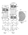
- Fig. 1
- eine schematische Darstellung des Destillationsapparates mit oberem Katalysator,
- Fig. 2
- eine Variante mit zusätzlichem bekanntem Katalysator und
- Fig. 3
- einen Schnitt durch eine Katalysatorfläche.
- Fig. 1
- 1 shows a schematic representation of the distillation apparatus with an upper catalyst,
- Fig. 2
- a variant with an additional known catalyst and
- Fig. 3
- a section through a catalyst surface.
Die in den Figuren 1 und 2 dargestellte Destillationsapparatur 1 ist in ihrem prinzipiellen Aufbau zunächst gleich aufgebaut wie die in der EP 0 343 260. Auf die entsprechende Beschreibung wird verwiesen.The basic structure of the
In einer nicht näher dargestellten beheizten Brennblase wird eingelagerte Maische zur Durchführung des Destillationsvorganges erhitzt. Oberhalb der Brennblase befindet sich eine Verstärkerkolonne 2, bestehend aus drei Verstärkerböden bzw. Glockenböden 3 bis 5. Zwischen dem untersten Verstärkerboden 3 und der nicht näher dargestellten Brennblase ist ein Prallblech 6 als Überkochvorrichtung angeordnet. Ein eventueller Rücklauf aus dem untersten Verstärkerboden 3 erfolgt über das Prallblech 6 und ein Rücklaufrohr 7 in die Maische.In a heated still, which is not shown in any more detail, stored mash is heated to carry out the distillation process. Above the still, there is an intensifying
Die Verstärkerböden 3 bis 5 sind in an sich bekannter Weise als Rektifikationskolonne ausgebildet. Oberhalb der Verstärkerböden 3 bis 5 befindet sich im Ausführungsbeispiel nach Fig. 2 ein Katalysator 8, wie er prinzipiell in der EP 0 343 260 näher beschrieben ist. In Durchflußrichtung der Destillationsapparatur folgt nach dem obersten Verstärkerboden 5 in Fig. 1 bzw. nach dem Katalysator 8 in Fig. 2 ein Dephlegmator 9 mit Kühleinrichtung 16 mit Wasserdurchlauf. Bei einer Gegenstromdestillation gemäß der vorliegenden Erfindung bewirken Verstärkerböden und Dephlegmator, daß dem von unten nach oben aufsteigenden Dampf stets ein Flüssigkeitsstrom entgegengeführt wird, so daß es zu einer innigen Berührung von Dampf und Flüssigkeit und damit zu einem gegenseitigen Wärme- und Stoffaustausch kommt. Dabei wird ein beim Durchgang durch die Destillationsapparatur kondensierender Dampf nicht voll als Destillat abgenommen, sondern vielmehr ein Teil des Kondensats stets wieder in die flüssige Form zurückgeführt, so daß ein mehrfaches Aufkochen und damit Destillieren erfolgt.The amplifier trays 3 to 5 are designed in a manner known per se as a rectification column. In the exemplary embodiment according to FIG. 2, a catalytic converter 8 is located above the amplifier trays 3 to 5, as is described in principle in EP 0 343 260. In the flow direction of the distillation apparatus, a
Bei der nach Fig. 2 dargestellten Ausführungsform wird ein vom obersten Verstärkerboden 5 aufsteigende Alkoholdampf durch den Katalysator 8 geleitet, der aus einer Vielzahl von Kupferrohren bzw. Kupferlamellen zur Bildung einer großen Oberfläche besteht. Dabei wird dieser Katalysator 8 vom rücklaufenden Phlegma des darüberliegenden Dephlegmators 9 je nach Kühlung 16 des Dephlegmators gleichmäßig benetzt. Die Benetzung liegt dabei bei ca. 2/3 der aufsteigenden Dampfmenge, d. h. 2/3 des in den Dephlegmator gelangenden Alkoholdampfs wird als Kondensator zurückgeschickt und durchläuft den ggf. vorhandenen unteren Katalysator 8.In the embodiment shown in FIG. 2, an alcohol vapor rising from the top amplifier base 5 is passed through the catalyst 8, which consists of a large number of copper tubes or copper fins to form a large surface. This catalyst 8 is uniformly wetted by the refluxing phlegm of the
Erfindungsgemäß ist in Fig. 1 und 2 unmittelbar oberhalb des Dephlegmators 9 ein Katalysator 10 vorgesehen, der prinzipiell gleich aufgebaut sein kann, wie der Katalysator 8 unterhalb des Dephlegmators 9 beim Ausführungsbeispiel nach Fig. 2. Dieser Kupferkatalysator muß lediglich noch den restlichen Alkoholdampf verarbeiten, der den Dephlegmator 9 passiert und nach oben durch das Geistrohr 11 abgeführt wird. Da diese Alkoholmenge nur ca. 1/3 der von den Verstärkerböden aufsteigenden Dampfmenge beträgt - 2/3 wird im Dephlegmator zurückgeführt - wird einer geringeren Dampfmenge eine wesentlich erhöhte Kupferoberfläche pro aufsteigender Alkoholdampfmenge zur Verfügung gestellt, was zu einer erheblichen Verbesserung der Reduzierung des Cyanidgehalts bzw. des Ethylcarbamat-Gehalts im Destillat führt.According to the invention, a
Der Katalysator 10 ist unittelbar oberhalb des Dephlegmators 9, d. h. noch innerhalb der Destillationsapparatur angeordnet. Dabei erstreckt sich sein Querschnitt über den gesamten Strömungsquerschnitt der aufsteigenden Alkoholdämpfe. Erst hierdurch kann eine vollständige Berührung der Dämpfe mit der Katalysatoroberfläche 10 erfolgen. Hierbei spielt die Struktur des Katalysators 10 - wie im Schnitt in Fig. 3 dargestellt - eine wichtige Rolle. Um keine Strömungsverluste durch einen Druckabfall im Katalysator 10 zu bekommen, sind die Lamellen im Katalysator 10 derart ausgebildet, daß die axiale Durchströmung der Dämpfe völlig ohne Druckabfall erfolgen kann, d. h. der Katalysator 10 weist in seiner axialen Längsrichtung keinerlei Schikanen, Vorsprünge oder sonstige Umlenkungen auf, die einen Druckverlust erzeugen könnten. Der Katalysator 10 wird demnach "sanft" durchströmt ohne daß ein bemerkenswerter Rückfluß an Kondensat eintritt. Hierdurch findte eine entscheidende Verbesserung der Reduzierung des Cyanidgehalts statt.The
Je nach Anwendungsfall wird deshalb die erfindungsgemäße Vorrichtung nach dem erfindungsgemäßen Verfahren entweder mit einem unterhalb des Dephlegmators 9 angeordneten zusätzlichen Katalysator 8 (Fig. 2) oder lediglich mit einem darüber angeordneten Katalysator 10 (Fig. 1) gefahren. Wird nur ein geringer Rückfluß des Phlegmas aufgrund der Kühlung des Dephlegmators 9 eingestellt, so kann es ggf. ausreichen, die Anlage nur mit dem oberen Katalysator 10 zu betreiben. Im übrigen verbessern sich die Werte, wenn man beide Katalysatoren 8 und 10 verwendet.Depending on the application, the device according to the invention is therefore operated according to the method according to the invention either with an additional catalyst 8 (FIG. 2) arranged below the
Zur Reinigung der Katalysatoren 8, 10 ist oberhalb derselben eine Reinigungsvorrichtung 12 vorgesehen, die die Reinigung aufgrund der Anordnung des Katalysators innerhalb der Destillationsvorrichtung sehr erleichtert. Dies gilt auch im Hinblick auf den axial ungehinderten Durchgang durch den Katalysator.To clean the
Sowohl bei der Ausführungsform nach Fig. 1 oder nach Fig. 2 können die Katalysatoren mit einer z. B. zentralen, verschließbaren Durchgangsbohrung 14 versehen sein. Bei einem Katalysator-Außendurchmesser von ca. D ∼ 400 - 450 mm beträgt der Bohrungsdurchmesser d ∼ 100 mm. Je nach zu behandelndem Stoff kann die Durchgangsbohrung 14 mittels einer oder mehrerer ggf. regelbarer Schwenkklappen 15 geöffnet oder verschlossen werden. Die Öffnung bewirkt einen ungehinderten Durchgang des aufsteigenden Alkoholdampfs, d. h. einer Verminderung der Katalysatorwirkung. Dies kann insbesondere bei solchen Stoffen durchgeführt werden, bei denen der EC-Gehalt weniger problematisch ist.Both in the embodiment of Fig. 1 or Fig. 2, the catalysts with a z. B. central, closable through
Claims (8)
Applications Claiming Priority (4)
| Application Number | Priority Date | Filing Date | Title |
|---|---|---|---|
| DE4016842 | 1990-05-25 | ||
| DE4016842 | 1990-05-25 | ||
| DE4114018 | 1991-04-29 | ||
| DE4114018 | 1991-04-29 |
Publications (2)
| Publication Number | Publication Date |
|---|---|
| EP0459310A1 true EP0459310A1 (en) | 1991-12-04 |
| EP0459310B1 EP0459310B1 (en) | 1996-01-31 |
Family
ID=25893533
Family Applications (1)
| Application Number | Title | Priority Date | Filing Date |
|---|---|---|---|
| EP91108405A Expired - Lifetime EP0459310B1 (en) | 1990-05-25 | 1991-05-24 | Process and device for the treatment of fruit spirits |
Country Status (3)
| Country | Link |
|---|---|
| EP (1) | EP0459310B1 (en) |
| AT (1) | ATE133575T1 (en) |
| DE (1) | DE59107328D1 (en) |
Cited By (5)
| Publication number | Priority date | Publication date | Assignee | Title |
|---|---|---|---|---|
| WO1993016168A1 (en) * | 1992-02-14 | 1993-08-19 | Oy Alko Ab | Procedure and apparatus for producing whisky |
| GB2278849A (en) * | 1992-02-14 | 1994-12-14 | Alko Ab Oy | Procedure and apparatus for producing whisky |
| FR2841257A1 (en) * | 2002-06-20 | 2003-12-26 | Jas Hennessy & C Soc | ALAMBIC WITH INCREASED CAPACITY, ENSURING HIGH QUALITY DISTILLATION |
| ITMI20130952A1 (en) * | 2013-06-10 | 2014-12-11 | Green Engineering S R L | COMPONENTS OF A DISTILLATION SYSTEM, METHOD FOR THEIR PRODUCTION AND THEIR DERIVED USES |
| CN115926924A (en) * | 2022-07-22 | 2023-04-07 | 金徽酒股份有限公司 | Method for reducing acetic acid content and protecting acid content of strong aromatic raw wine |
Families Citing this family (1)
| Publication number | Priority date | Publication date | Assignee | Title |
|---|---|---|---|---|
| DE102020118701A1 (en) * | 2020-07-15 | 2022-01-20 | Ulrich Kothe | Container cascade for use in a firing device |
Citations (2)
| Publication number | Priority date | Publication date | Assignee | Title |
|---|---|---|---|---|
| DE8906105U1 (en) * | 1989-05-17 | 1989-07-06 | Kothe, Ulrich, 7332 Eislingen | Catalyst device for distillery equipment |
| EP0343260A1 (en) * | 1988-05-02 | 1989-11-29 | Firma Arnold Holstein | Process and device for the treatment of fruit spirits |
-
1991
- 1991-05-24 DE DE59107328T patent/DE59107328D1/en not_active Expired - Lifetime
- 1991-05-24 AT AT91108405T patent/ATE133575T1/en not_active IP Right Cessation
- 1991-05-24 EP EP91108405A patent/EP0459310B1/en not_active Expired - Lifetime
Patent Citations (2)
| Publication number | Priority date | Publication date | Assignee | Title |
|---|---|---|---|---|
| EP0343260A1 (en) * | 1988-05-02 | 1989-11-29 | Firma Arnold Holstein | Process and device for the treatment of fruit spirits |
| DE8906105U1 (en) * | 1989-05-17 | 1989-07-06 | Kothe, Ulrich, 7332 Eislingen | Catalyst device for distillery equipment |
Non-Patent Citations (2)
| Title |
|---|
| PATENT ABSTRACTS OF JAPAN vol. 9, no. 17 (C-262)24. Januar 1985 & JP-A-59 166 077 (BISHIYOUNEN SHIYUZOU ) 19. September 1984 * |
| SCHWEIZERISCHE ZEITSCHRIFT FÜR OBST- UND WEINBAU Bd. 123, Nr. 22, 1987, WAEDENSWILL, CH Seiten 595 - 597; E. RITZMANN ET ALL: 'HERSTELLUNG VON STEINOBSTDESTILLATEN MITTELS EINER RASCHIGRING-KOLONNE ' * |
Cited By (10)
| Publication number | Priority date | Publication date | Assignee | Title |
|---|---|---|---|---|
| WO1993016168A1 (en) * | 1992-02-14 | 1993-08-19 | Oy Alko Ab | Procedure and apparatus for producing whisky |
| GB2278849A (en) * | 1992-02-14 | 1994-12-14 | Alko Ab Oy | Procedure and apparatus for producing whisky |
| GB2278849B (en) * | 1992-02-14 | 1996-05-22 | Alko Ab Oy | Procedure and apparatus for producing whisky |
| FR2841257A1 (en) * | 2002-06-20 | 2003-12-26 | Jas Hennessy & C Soc | ALAMBIC WITH INCREASED CAPACITY, ENSURING HIGH QUALITY DISTILLATION |
| WO2004000991A1 (en) * | 2002-06-20 | 2003-12-31 | Societe Jas Hennessy & Co | Increased-capacity still for high-quality distillation |
| US7527710B2 (en) | 2002-06-20 | 2009-05-05 | Societe Jas Hennessy & Co. | Increased-capacity still for high-quality distillation |
| ITMI20130952A1 (en) * | 2013-06-10 | 2014-12-11 | Green Engineering S R L | COMPONENTS OF A DISTILLATION SYSTEM, METHOD FOR THEIR PRODUCTION AND THEIR DERIVED USES |
| WO2014199252A1 (en) * | 2013-06-10 | 2014-12-18 | Green Engineering S.R.L. | Components of a distillation apparatus, method for their production and uses thereof |
| US10603602B2 (en) | 2013-06-10 | 2020-03-31 | Green Engineering S.R.L. | Components of a distillation apparatus, method for their production and uses thereof |
| CN115926924A (en) * | 2022-07-22 | 2023-04-07 | 金徽酒股份有限公司 | Method for reducing acetic acid content and protecting acid content of strong aromatic raw wine |
Also Published As
| Publication number | Publication date |
|---|---|
| EP0459310B1 (en) | 1996-01-31 |
| ATE133575T1 (en) | 1996-02-15 |
| DE59107328D1 (en) | 1996-03-14 |
Similar Documents
| Publication | Publication Date | Title |
|---|---|---|
| DE2943687C2 (en) | Trough-like device for collecting and distributing the liquid for a countercurrent column | |
| EP0343260B1 (en) | Process and device for the treatment of fruit spirits | |
| DE2442603A1 (en) | STEAM-LIQUID CONTACT PROCEDURE AND DEVICE FOR CARRYING OUT THE PROCEDURE | |
| CH658198A5 (en) | LIQUID DISTRIBUTOR IN A SUBSTANCE AND HEAT EXCHANGE COLUMN. | |
| EP0574675A1 (en) | Moving bed reactor installation | |
| EP0459310B1 (en) | Process and device for the treatment of fruit spirits | |
| DE3341603A1 (en) | METHOD AND DEVICES FOR REDUCING THE ALCOHOL CONTENT OF ORIGINAL WINE | |
| DE2834358C3 (en) | Catalytic reactor | |
| WO1999001215A1 (en) | Baffles for material exchange columns | |
| DE2827687A1 (en) | SIEBBODENTURM | |
| CH678922A5 (en) | ||
| DE2524080C3 (en) | Heat exchanger in which a vaporous medium condenses while giving off heat to another medium | |
| DE4116946A1 (en) | Distn. of fruit brandy to reduce cyanide content | |
| DE69515877T2 (en) | COLUMN TO CONTACT GAS AND LIQUID | |
| EP0463448B1 (en) | Method and apparatus for heating and multiple effect degasification of water | |
| DE218029C (en) | ||
| DE2605287A1 (en) | PROCESS FOR THE REMOVAL OF ACID COMPONENTS FROM GASES | |
| DE193737C (en) | ||
| DE1167312B (en) | Mass transfer column | |
| DE1444367A1 (en) | Mass transfer column | |
| DE4118468A1 (en) | Separator column for sepg. contents of mixt. by rectification - useful for liq. hydrocarbon(s) of differing b.pt. from gas mixt. with run=off shaft in heat exchanger | |
| DE2811911A1 (en) | WASTE WATER PURIFICATION METHOD | |
| DE1667025C3 (en) | Reactor for catalytic processes in a fluidized bed | |
| AT17579B (en) | Method and device for distilling and rectifying liquids, in particular alcohol. | |
| DE103573C (en) |
Legal Events
| Date | Code | Title | Description |
|---|---|---|---|
| PUAI | Public reference made under article 153(3) epc to a published international application that has entered the european phase |
Free format text: ORIGINAL CODE: 0009012 |
|
| AK | Designated contracting states |
Kind code of ref document: A1 Designated state(s): AT CH DE FR IT LI LU |
|
| 17P | Request for examination filed |
Effective date: 19920413 |
|
| 17Q | First examination report despatched |
Effective date: 19940630 |
|
| GRAA | (expected) grant |
Free format text: ORIGINAL CODE: 0009210 |
|
| AK | Designated contracting states |
Kind code of ref document: B1 Designated state(s): AT CH DE FR IT LI LU |
|
| REF | Corresponds to: |
Ref document number: 133575 Country of ref document: AT Date of ref document: 19960215 Kind code of ref document: T |
|
| REF | Corresponds to: |
Ref document number: 59107328 Country of ref document: DE Date of ref document: 19960314 |
|
| REG | Reference to a national code |
Ref country code: CH Ref legal event code: NV Representative=s name: KELLER & PARTNER PATENTANWAELTE AG |
|
| ET | Fr: translation filed | ||
| ITF | It: translation for a ep patent filed | ||
| PLBE | No opposition filed within time limit |
Free format text: ORIGINAL CODE: 0009261 |
|
| STAA | Information on the status of an ep patent application or granted ep patent |
Free format text: STATUS: NO OPPOSITION FILED WITHIN TIME LIMIT |
|
| 26N | No opposition filed | ||
| PGFP | Annual fee paid to national office [announced via postgrant information from national office to epo] |
Ref country code: LU Payment date: 20080515 Year of fee payment: 18 |
|
| PGFP | Annual fee paid to national office [announced via postgrant information from national office to epo] |
Ref country code: AT Payment date: 20080513 Year of fee payment: 18 |
|
| PGFP | Annual fee paid to national office [announced via postgrant information from national office to epo] |
Ref country code: FR Payment date: 20080523 Year of fee payment: 18 Ref country code: IT Payment date: 20080527 Year of fee payment: 18 |
|
| PG25 | Lapsed in a contracting state [announced via postgrant information from national office to epo] |
Ref country code: AT Free format text: LAPSE BECAUSE OF NON-PAYMENT OF DUE FEES Effective date: 20090524 |
|
| REG | Reference to a national code |
Ref country code: FR Ref legal event code: ST Effective date: 20100129 |
|
| PG25 | Lapsed in a contracting state [announced via postgrant information from national office to epo] |
Ref country code: FR Free format text: LAPSE BECAUSE OF NON-PAYMENT OF DUE FEES Effective date: 20090602 |
|
| PGFP | Annual fee paid to national office [announced via postgrant information from national office to epo] |
Ref country code: DE Payment date: 20100609 Year of fee payment: 20 |
|
| PGFP | Annual fee paid to national office [announced via postgrant information from national office to epo] |
Ref country code: CH Payment date: 20100520 Year of fee payment: 20 |
|
| PG25 | Lapsed in a contracting state [announced via postgrant information from national office to epo] |
Ref country code: IT Free format text: LAPSE BECAUSE OF NON-PAYMENT OF DUE FEES Effective date: 20090524 |
|
| PG25 | Lapsed in a contracting state [announced via postgrant information from national office to epo] |
Ref country code: LU Free format text: LAPSE BECAUSE OF NON-PAYMENT OF DUE FEES Effective date: 20090524 |
|
| REG | Reference to a national code |
Ref country code: DE Ref legal event code: R071 Ref document number: 59107328 Country of ref document: DE |
|
| REG | Reference to a national code |
Ref country code: CH Ref legal event code: PL |
|
| PG25 | Lapsed in a contracting state [announced via postgrant information from national office to epo] |
Ref country code: DE Free format text: LAPSE BECAUSE OF EXPIRATION OF PROTECTION Effective date: 20110525 |