EP0459064A1 - Mesure dans un puits de caractéristiques NMR de formations géologique et leur interprétation - Google Patents
Mesure dans un puits de caractéristiques NMR de formations géologique et leur interprétation Download PDFInfo
- Publication number
- EP0459064A1 EP0459064A1 EP90401475A EP90401475A EP0459064A1 EP 0459064 A1 EP0459064 A1 EP 0459064A1 EP 90401475 A EP90401475 A EP 90401475A EP 90401475 A EP90401475 A EP 90401475A EP 0459064 A1 EP0459064 A1 EP 0459064A1
- Authority
- EP
- European Patent Office
- Prior art keywords
- formation
- borehole
- magnetic
- volume
- antenna
- Prior art date
- Legal status (The legal status is an assumption and is not a legal conclusion. Google has not performed a legal analysis and makes no representation as to the accuracy of the status listed.)
- Granted
Links
- 230000015572 biosynthetic process Effects 0.000 title claims abstract description 142
- 238000005259 measurement Methods 0.000 title claims abstract description 64
- 238000005755 formation reaction Methods 0.000 title claims description 139
- 230000005291 magnetic effect Effects 0.000 claims abstract description 136
- 238000005481 NMR spectroscopy Methods 0.000 claims abstract description 75
- 238000000034 method Methods 0.000 claims abstract description 71
- 239000012530 fluid Substances 0.000 claims abstract description 33
- 230000003068 static effect Effects 0.000 claims abstract description 31
- 230000035699 permeability Effects 0.000 claims abstract description 29
- 230000010287 polarization Effects 0.000 claims abstract description 13
- 239000011148 porous material Substances 0.000 claims abstract description 11
- 239000002245 particle Substances 0.000 claims description 22
- 230000005415 magnetization Effects 0.000 claims description 15
- 230000004044 response Effects 0.000 claims description 14
- 230000005669 field effect Effects 0.000 claims description 2
- 239000012811 non-conductive material Substances 0.000 claims description 2
- 230000001747 exhibiting effect Effects 0.000 claims 1
- 238000000264 spin echo pulse sequence Methods 0.000 claims 1
- 239000011435 rock Substances 0.000 abstract description 15
- UFHFLCQGNIYNRP-UHFFFAOYSA-N Hydrogen Chemical compound [H][H] UFHFLCQGNIYNRP-UHFFFAOYSA-N 0.000 abstract description 14
- 229910052739 hydrogen Inorganic materials 0.000 abstract description 14
- 239000001257 hydrogen Substances 0.000 abstract description 14
- 238000013016 damping Methods 0.000 abstract description 8
- 229910052751 metal Inorganic materials 0.000 abstract description 6
- 239000002184 metal Substances 0.000 abstract description 6
- 230000005540 biological transmission Effects 0.000 abstract description 2
- 238000011835 investigation Methods 0.000 description 22
- 238000010586 diagram Methods 0.000 description 18
- 230000000694 effects Effects 0.000 description 9
- 230000006698 induction Effects 0.000 description 9
- 238000001514 detection method Methods 0.000 description 8
- 230000001965 increasing effect Effects 0.000 description 8
- 230000010354 integration Effects 0.000 description 6
- 239000000523 sample Substances 0.000 description 6
- 241000894007 species Species 0.000 description 6
- 238000012360 testing method Methods 0.000 description 6
- XLYOFNOQVPJJNP-UHFFFAOYSA-N water Substances O XLYOFNOQVPJJNP-UHFFFAOYSA-N 0.000 description 6
- 239000003990 capacitor Substances 0.000 description 5
- 230000000875 corresponding effect Effects 0.000 description 5
- 238000013461 design Methods 0.000 description 5
- 239000000463 material Substances 0.000 description 5
- 239000003208 petroleum Substances 0.000 description 5
- 238000005516 engineering process Methods 0.000 description 4
- 239000003129 oil well Substances 0.000 description 4
- 230000003287 optical effect Effects 0.000 description 4
- 239000000126 substance Substances 0.000 description 4
- 229910000859 α-Fe Inorganic materials 0.000 description 4
- 239000004606 Fillers/Extenders Substances 0.000 description 3
- 230000002411 adverse Effects 0.000 description 3
- 230000008901 benefit Effects 0.000 description 3
- 230000006870 function Effects 0.000 description 3
- 229930195733 hydrocarbon Natural products 0.000 description 3
- 150000002430 hydrocarbons Chemical class 0.000 description 3
- 230000001939 inductive effect Effects 0.000 description 3
- 238000011545 laboratory measurement Methods 0.000 description 3
- 229910001092 metal group alloy Inorganic materials 0.000 description 3
- 239000007769 metal material Substances 0.000 description 3
- 229910000938 samarium–cobalt magnet Inorganic materials 0.000 description 3
- 238000009738 saturating Methods 0.000 description 3
- 230000035945 sensitivity Effects 0.000 description 3
- 238000013459 approach Methods 0.000 description 2
- 238000004590 computer program Methods 0.000 description 2
- 239000000470 constituent Substances 0.000 description 2
- 230000007423 decrease Effects 0.000 description 2
- 230000009977 dual effect Effects 0.000 description 2
- 238000011156 evaluation Methods 0.000 description 2
- 239000011152 fibreglass Substances 0.000 description 2
- 230000003993 interaction Effects 0.000 description 2
- 239000006249 magnetic particle Substances 0.000 description 2
- 230000005311 nuclear magnetism Effects 0.000 description 2
- 230000005298 paramagnetic effect Effects 0.000 description 2
- 230000008569 process Effects 0.000 description 2
- 238000012545 processing Methods 0.000 description 2
- 238000006467 substitution reaction Methods 0.000 description 2
- 230000009466 transformation Effects 0.000 description 2
- 229910001369 Brass Inorganic materials 0.000 description 1
- OKTJSMMVPCPJKN-OUBTZVSYSA-N Carbon-13 Chemical compound [13C] OKTJSMMVPCPJKN-OUBTZVSYSA-N 0.000 description 1
- RYGMFSIKBFXOCR-UHFFFAOYSA-N Copper Chemical compound [Cu] RYGMFSIKBFXOCR-UHFFFAOYSA-N 0.000 description 1
- 235000015076 Shorea robusta Nutrition 0.000 description 1
- 244000166071 Shorea robusta Species 0.000 description 1
- BQCADISMDOOEFD-UHFFFAOYSA-N Silver Chemical compound [Ag] BQCADISMDOOEFD-UHFFFAOYSA-N 0.000 description 1
- 229910000831 Steel Inorganic materials 0.000 description 1
- 239000004809 Teflon Substances 0.000 description 1
- 229920006362 Teflon® Polymers 0.000 description 1
- 238000005299 abrasion Methods 0.000 description 1
- 229910002065 alloy metal Inorganic materials 0.000 description 1
- 239000010951 brass Substances 0.000 description 1
- 230000008859 change Effects 0.000 description 1
- KPLQYGBQNPPQGA-UHFFFAOYSA-N cobalt samarium Chemical compound [Co].[Sm] KPLQYGBQNPPQGA-UHFFFAOYSA-N 0.000 description 1
- 230000001427 coherent effect Effects 0.000 description 1
- 238000004891 communication Methods 0.000 description 1
- 239000000805 composite resin Substances 0.000 description 1
- 239000004020 conductor Substances 0.000 description 1
- 238000010276 construction Methods 0.000 description 1
- 229910052802 copper Inorganic materials 0.000 description 1
- 239000010949 copper Substances 0.000 description 1
- 230000002596 correlated effect Effects 0.000 description 1
- 230000008878 coupling Effects 0.000 description 1
- 238000010168 coupling process Methods 0.000 description 1
- 238000005859 coupling reaction Methods 0.000 description 1
- 230000003247 decreasing effect Effects 0.000 description 1
- 230000007812 deficiency Effects 0.000 description 1
- 230000005347 demagnetization Effects 0.000 description 1
- 230000001419 dependent effect Effects 0.000 description 1
- 238000009795 derivation Methods 0.000 description 1
- 238000009792 diffusion process Methods 0.000 description 1
- 230000002500 effect on skin Effects 0.000 description 1
- 230000007613 environmental effect Effects 0.000 description 1
- 239000002360 explosive Substances 0.000 description 1
- 239000000284 extract Substances 0.000 description 1
- 239000000706 filtrate Substances 0.000 description 1
- 238000006062 fragmentation reaction Methods 0.000 description 1
- 238000011065 in-situ storage Methods 0.000 description 1
- 230000008595 infiltration Effects 0.000 description 1
- 238000001764 infiltration Methods 0.000 description 1
- 208000014674 injury Diseases 0.000 description 1
- 150000002500 ions Chemical class 0.000 description 1
- SZVJSHCCFOBDDC-UHFFFAOYSA-N iron(II,III) oxide Inorganic materials O=[Fe]O[Fe]O[Fe]=O SZVJSHCCFOBDDC-UHFFFAOYSA-N 0.000 description 1
- 238000002955 isolation Methods 0.000 description 1
- 230000002045 lasting effect Effects 0.000 description 1
- 238000000691 measurement method Methods 0.000 description 1
- 230000007246 mechanism Effects 0.000 description 1
- 238000012986 modification Methods 0.000 description 1
- 230000004048 modification Effects 0.000 description 1
- 230000008450 motivation Effects 0.000 description 1
- 230000005405 multipole Effects 0.000 description 1
- 238000001208 nuclear magnetic resonance pulse sequence Methods 0.000 description 1
- 239000002907 paramagnetic material Substances 0.000 description 1
- 230000003071 parasitic effect Effects 0.000 description 1
- 239000000047 product Substances 0.000 description 1
- 230000035939 shock Effects 0.000 description 1
- 229910052709 silver Inorganic materials 0.000 description 1
- 239000004332 silver Substances 0.000 description 1
- 239000010959 steel Substances 0.000 description 1
- 229920003051 synthetic elastomer Polymers 0.000 description 1
- 239000005061 synthetic rubber Substances 0.000 description 1
- 230000008733 trauma Effects 0.000 description 1
Images


Classifications
-
- G—PHYSICS
- G01—MEASURING; TESTING
- G01R—MEASURING ELECTRIC VARIABLES; MEASURING MAGNETIC VARIABLES
- G01R33/00—Arrangements or instruments for measuring magnetic variables
- G01R33/20—Arrangements or instruments for measuring magnetic variables involving magnetic resonance
- G01R33/28—Details of apparatus provided for in groups G01R33/44 - G01R33/64
- G01R33/32—Excitation or detection systems, e.g. using radio frequency signals
- G01R33/34—Constructional details, e.g. resonators, specially adapted to MR
- G01R33/341—Constructional details, e.g. resonators, specially adapted to MR comprising surface coils
-
- G—PHYSICS
- G01—MEASURING; TESTING
- G01N—INVESTIGATING OR ANALYSING MATERIALS BY DETERMINING THEIR CHEMICAL OR PHYSICAL PROPERTIES
- G01N24/00—Investigating or analyzing materials by the use of nuclear magnetic resonance, electron paramagnetic resonance or other spin effects
- G01N24/08—Investigating or analyzing materials by the use of nuclear magnetic resonance, electron paramagnetic resonance or other spin effects by using nuclear magnetic resonance
- G01N24/081—Making measurements of geologic samples, e.g. measurements of moisture, pH, porosity, permeability, tortuosity or viscosity
-
- G—PHYSICS
- G01—MEASURING; TESTING
- G01R—MEASURING ELECTRIC VARIABLES; MEASURING MAGNETIC VARIABLES
- G01R33/00—Arrangements or instruments for measuring magnetic variables
- G01R33/20—Arrangements or instruments for measuring magnetic variables involving magnetic resonance
- G01R33/28—Details of apparatus provided for in groups G01R33/44 - G01R33/64
- G01R33/32—Excitation or detection systems, e.g. using radio frequency signals
- G01R33/36—Electrical details, e.g. matching or coupling of the coil to the receiver
- G01R33/3671—Electrical details, e.g. matching or coupling of the coil to the receiver involving modulation of the quality factor of the RF coil
-
- G—PHYSICS
- G01—MEASURING; TESTING
- G01R—MEASURING ELECTRIC VARIABLES; MEASURING MAGNETIC VARIABLES
- G01R33/00—Arrangements or instruments for measuring magnetic variables
- G01R33/20—Arrangements or instruments for measuring magnetic variables involving magnetic resonance
- G01R33/28—Details of apparatus provided for in groups G01R33/44 - G01R33/64
- G01R33/38—Systems for generation, homogenisation or stabilisation of the main or gradient magnetic field
- G01R33/3808—Magnet assemblies for single-sided MR wherein the magnet assembly is located on one side of a subject only; Magnet assemblies for inside-out MR, e.g. for MR in a borehole or in a blood vessel, or magnet assemblies for fringe-field MR
-
- G—PHYSICS
- G01—MEASURING; TESTING
- G01V—GEOPHYSICS; GRAVITATIONAL MEASUREMENTS; DETECTING MASSES OR OBJECTS; TAGS
- G01V3/00—Electric or magnetic prospecting or detecting; Measuring magnetic field characteristics of the earth, e.g. declination, deviation
- G01V3/18—Electric or magnetic prospecting or detecting; Measuring magnetic field characteristics of the earth, e.g. declination, deviation specially adapted for well-logging
- G01V3/32—Electric or magnetic prospecting or detecting; Measuring magnetic field characteristics of the earth, e.g. declination, deviation specially adapted for well-logging operating with electron or nuclear magnetic resonance
Definitions
- This invention relates to apparatus and techniques for making nuclear magnetic resonance (NMR) measurements in boreholes, and to methods for determining magnetic characteristics of formations traversed by a borehole.
- NMR nuclear magnetic resonance
- any particles of a formation having magnetic spin for example atomic nuclei, protons, or electrons, have tendencies to align with a magnetic field which is imposed on the formation.
- Such a magnetic field may be naturally generated, as is the case with the earth's magnetic field B E which has an intensity of approximately 0.5 gauss in areas of the globe where boreholes are typically drilled.
- Any given particle in a formation is additionally influenced by localized magnetic fields associated with nearby magnetic particles other paramagnetic materials, and the layer of ions which typically line pore walls of certain types of formations such as shales. These localized fields tend to be inhomogeneous, while the earth's magnetic field is relatively homogeneous.
- the hydrogen nuclei (protons) of water and hydrocarbons occurring in rock pores produce NMR signals distinct from any signals induced in other rock constituents.
- a population of such nuclei, having a net magnetization, tends to align with any imposed field such as B E .
- the combined magnetic fields of all the protons can generate a detectable oscillating voltage in a receiver coil. Since the magnetic moment of each proton produces field inhomogeneities, the precessing protons tend to lose their phase coherence over time, with a characteristic time constant called the transverse or spin-spin relaxation time T 2 . Furthermore, field inhomogeneities are also produced by other physical phenomena as mentioned above, so that the observed dephasing relaxation time T 2 * is usually shorter than T 2 . Borehole magnetic resonance measurements of the above type are commercially available as a part of the NML ⁇ service Schlumberger Technology Corporation, Houston, Texas ( ⁇ Mark of Schlumberger).
- This tool is capable of measuring the Free Induction Decay of hydrogen nuclei in formation fluids, and to obtain the parameters T 1 and T 2 * . It does not measure the transverse relaxation time T 2 .
- a description of the basic components, operation and interpretation of the commercial logging tool used in the NML service is contained in a paper entitled, " An Improved Nuclear Magnetism Logging System and its Application to Formation Evaluation ", by R. C. Herrick, S. H. Couturie and D. L. Best, presented at the 54th Annual Fall Technical Conference and Exhibition of the Society of Petroleum Engineers (A.I.M.E., Dallas, Texas) in Las Vegas, Nevada, September 23-26, 1979; this paper, appended hereto, is incorporated herein by reference.
- sequences of magnetic fields can be imposed on a population of protons in a formation, to measure other characteristics thereof. For example, if a pulse of alternating current having a frequency f is passed through a transmitter coil, producing an oscillating polarizing field B 1 perpendicular to a static field B 0 , a population of protons precessing at a Larmor frequency equal to f would tend to align at an angle to B 1 . At the end of the pulse, when B 1 is removed, the aligned protons experience a perpendicular torque, and precess about the B 0 vector.
- the protons After a characteristic time called the longitudinal or spin-lattice relaxation time T 1 , the protons have relaxed to thermal equilibrium, wherein a weighted percentage of protons are aligned in the direction of B 0 .
- T 1 a characteristic time
- Various other sequences of imposed magnetic fields can be used, as is discussed in T.C. Farrar and E.D. Becker, " Pulse and Fourier Transform Nuclear Magnetic Resonance ", Academic Press, N.Y. (1971), Chapter 2, pp. 18-33, which is incorporated herein by reference.
- bar magnet is used herein to mean any magnet having only one north pole and one south pole, facing opposite directions, and may be either a permanent magnet or an electromagnet.
- Both the Slichter design and the Schuster design use electromagnets which require inconveniently large D.C. currents to be transmitted to a logging sonde through many thousands of feet of electrical cable.
- U.S. Patent No. 3,528,000 granted September 8,1970 to H. F. Schwede shows one type of NMR logging tool in Figs. 8 and 9, wherein a permanent magnet produces a first magnetic field which is fixed in its intensity, and an inductive coil produces an oscillating magnetic field whose frequency is varied over a selected range. Since the first magnetic field is produced by two opposite magnetic poles (one N and one S) placed side by side, the field is not homogeneous and the spatial gradient of the field is evidently non-zero at all points in the formation.
- first and second fields intersect not only in the formation, but also within the borehole, it is evident that protons constituting water or hydrocarbons within the borehole fluid contributes to signals detected by the RF coil, and must be removed either electronically or by chemically treating the borehole fluid, if a true formation measurement is desired.
- NMR logging tools which use permanent bar magnets, aligned coaxially in a logging sonde with a detection coil positioned in the gap between the magnets, for example as shown in U.S. Patent No. 3,597,681 granted August 3, 1971 to W. B. Huckabay.
- the tool is designed to produce the toroidal region far away from the tool body, the produced magnetic field becomes much weaker, resulting in a significantly weaker signal.
- This configuration further requires that the detection coil or antenna be enclosed by a structure which would not block the oscillating electromagnetic waves of the measured signal.
- fiberglass or some other non-metallic material is typically used; unfortunately, this structurally weakened link decreases the structural integrity of the tool and renders it considerably less useful in rough borehole conditions.
- Previous NMR logging tools typically required approximately 20-30 milliseconds, called “dead time", after a polarizing field pulse is shut and before the transmitting coil is sufficiently damped to permit measurements to be taken. During this dead time, considerable information of magnetic relaxation is irretrievably lost, and the S/N ratio is considerably degraded.
- the commercially available NMR logging tool cannot directly measure the spin-spin relaxation time T 2. Instead, the existing commercial tool obtains measures of the Free Fluid Index (FFI) and the observable dephasing relaxation time T 2 * , also called the free induction decay time constant.
- FFI Free Fluid Index
- T 2 * also called the free induction decay time constant.
- Various log interpretation techniques may be used to derive other useful information as discussed in, e.g. " Applications of Nuclear Magnetism Logging to Formation Evaluation" by C. H. Neuman and R. J. S. Brown, Journal of Petroleum Technology (Dec. 1982) pp. 2853-2860, and in the Herrick et al. paper cited above.
- the basic purpose of making NMR measurements in boreholes is to obtain information of formation constituents surrounding the borehole.
- Such information typically relate to magnetic relaxation times of the hydrogen nuclei in water and hydrocarbons, but it also can relate to other physical parameters or other particles in the formation.
- a large polarizing current (with a power on the order of 1 KW) is shut off and, after the coil has been fully damped, requiring about 25 milliseconds, measurement circuits are coupled to the coil to detect signals induced therein by the population of protons in the formation which now freely precess about the earth's magnetic field B E .
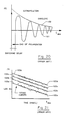
- This Free Induction Decay signal called the " FID " has a frequency equal to the Larmor frequency ⁇ L in the earth's field which is about 2 kHz, as shown in Fig. 20.
- the basic NMR measurement is an induced voltage in a conductive coil located in the borehole.
- the amplitude, frequency and phase of this voltage signal must then be correlated with secondary parameters which tell us something about the magnetic characteristics of the measured population of protons, namely T 1 , T 2 , T 2 * .
- the secondary parameters, to be of use, must then be linked to an interpretations method which obtains desired information such as the fluid porosity, viscosity, permeability, or water cut of the measured formation.
- Fig. 20 it has been known in the prior art to measure the decay envelope of the 2 kHz free induction decay signal, and then to extrapolate the envelope to the initial time t 0 at which the polarizing pulse B p was shut off.
- the voltage amplitude at t 0 when multiplied by calibration constants which depend on design parameters of the particular tool, yields * (Mark of Schlumberger) the Free Fluid Index (FFI) also called the free fluid porosity ( ⁇ f ).
- the FID decay curve is known to be associated with the observable dephasing time constant T 2 * .
- the NML tool can also be used in a "T 1 Stationary Mode" of operation wherein a plurality of non-saturating polarizing pulses are applied to the formation while the tool remains stationary in the borehole at the measuring depth.
- the free induction decay signal is measured and a decay envelope estimated, as before, to extrapolate the formation magnetization at the time t 0 when the polarizing pulse was shut off, and this is successively done for each period of polarization, a, b, c and d.
- T 1 Build-Up curve which has a characteristic time constant equal to the longitudinal relaxation time T 1 .
- T 1 typically was estimated by fitting the T 1 Build-Up curve to an exponential decay function, using commercially available "least squares fit" computer programs.
- T 1 is based on a desire to determine the fluid flow permeability, k, using certain known correlations between k and T 1 , as is discussed in the literature, e.g ., A. Timur, "Pulsed Nuclear Magnetic Resonance Studies of Porosity. Movable Fluid and Permeability of Sand Stones ", Journal of Petroleum Technology (June 1969), pp. 775-786.
- apparatus which produces a static and substantially homogeneous magnetic field focussed into a formation on one side of the logging tool.
- a region remote from the configuration of magnets, wherein the spacial field gradient substantially vanishes, thereby insuring that the field is highly homogeneous throughout that region.
- the magnets are mounted within a skid or logging pad, the static magnetic field is directed through the face of the pad into an adjacent formation, and the region of substantially homogeneous field is situated in a volume of formation behind the mudcake layer which typically lines borehole walls.
- a homogeneous magnetic field several hundred times stronger than the earth's magnetic field can be thus imposed, or "focused", on a volume of formation in situ.
- the RF antenna is mounted on the outside of the metallic structure of the tool so that the tool body serves as a natural shield against any signals which may be generated by resonant conditions behind the body, particularly those potentially strong resonance signals from borehole fluid.
- the antenna is configured to focus its signals radially outwardly from the pad face, into the volume of formation having the homogeneous field, thereby additionally reducing the distortion of measured signals from borehole effects.
- the logging apparatus may be constructed of strong metallic alloys, unlike prior art tools, and the present measurement technique actually uses the shielding effect of a metal sonde to good advantage, to enhance the S/N ratio of NMR measurement. Since borehole effects are excluded by the dual focussed design, it is no longer necessary to pretreat the borehole fluid with paramagnetic chemicals.
- an elongated trough antenna is provided on a pad face, parallel to the borehole axis and to an elongated volume of substantially homogeneous static magnetic field in the adjacent formation.
- the static field is directed radially into said volume, while the RF field is circumferentially directed and thus perpendicular to the static homogeneous field within the volume of investigation.
- the length of the trough antenna is preferably about equal to the length of the volume of investigation.
- methods and apparatus are provided for making fast pulsed measurements of magnetic resonance in earth formations surrounding a borehole, particularly the direct measurement of spin-spin relaxation time T 2 , to determine formation characteristics.
- the transmitting antenna is also used for receiving magnetic resonance signals, and special circuitry is used to very rapidly damp the ringing current which occurs in the antenna after a power shut-off.
- the special circuitry called a Q-Switch, damps the polarizing antenna current about 1000 times faster than the previous tool, and enables many pulses to be injected successively into a formation in a short period of time.
- the present invention enables the logging tool to: (1) increase the S/N of the overall measured data set, thereby permitting either a faster logging rate or continuous logging, and (2) reduce the NMR measurement time during which nuclei may diffuse within rock pores, thereby reducing the undesirable magnetic effects of such diffusion.
- additional apparatus is provided to prepolarize a formation volume of interest before the main magnetic configuration reaches proximity to the formation.
- the prepolarization field is preferably much stronger than that of the main magnet configuration, and serves to increase the population of protons that is aligned in the B 0 vector direction, and thus further increases the magnetic precession signal level.
- small currents are introduced in the vicinity of a measuring tool to alter the static field during part of the measurement cycle to spoil the signals from these localized regions.
- the small currents flow through a wire preferably configured as a loop covering the antenna opening and attached parallel to the wall-engaging face of the tool.
- This configuration serves to significantly reduce or eliminate any resonance signals produced by borehole mud or mudcake immediately adjacent to the antenna surface, and substantially reduces undesirable signals.
- the spatial extent and magnetic effects of these field inhomogeneities can be carefully controlled by selecting the spacing of adjacent sectors of the wire, the current, and other relevant dimensions.
- the wire or its equivalent can be used to produce magnetic field gradients extending into the volume of measured resonance, which permits other advantageous magnetic measurements to be made.
- methods are provided for interpreting the measured data, such as free induction decay signals, pulse sequence type magnetization curves, and other magnetic resonance measurements, to determine the values of formation pore fluid characteristics such as permeability.
- a borehole 10 is shown adjacent to formations 11, 12, the characteristics of which are to be determined.
- a logging tool 13 connected via a wireline 8 to surface equipment 7.
- Tool 13 preferably has a face 14 shaped to intimately contact the borehole wall, with minimal gaps or standoff.
- the tool 13 also has a retractable arm 15 which can be activated to press the body of the tool 13 against the borehole wall during a logging run, with the face 14 pressed against the wall's surface.
- tool 13 is shown in the preferred embodiment of Fig. 1 as a single body, the tool may obviously comprise separate components such as a cartridge, sonde or skid, and the tool may be combinable with other logging tools as would be obvious to those skilled in the art.
- wireline 8 is the preferred form of physical support and communicating link for the invention, alternatives are clearly possible, and the invention can be incorporated in a drill stem, for example, using forms of telemetry which may not require a wireline.
- the formations 11, 12 have distinct characteristics such as formation type, porosity, permeability and oil content, which can be determined from measurements taken by the tool.
- Deposited upon the borehole wall of formations 11, 12 is typically a layer of mudcake 16 which is deposited thereon by the natural infiltration of borehole fluid filtrate into the formations.
- tool 13 comprises a magnet array 17 and an antenna 18 positioned between the array 17 and the wall engaging face 14.
- Magnet array 17 produces a static magnetic field B 0 in all regions surrounding the tool 13.
- the antenna 18 produces, at selected times, an oscillating magnetic field B 1 which is focussed into formation 12, and is superposed on the static field B 0 within those parts of formation opposite the face 14.
- the Volume of Investigation of the tool shown in dotted lines in Fig. 1, is a vertically elongated region directly in front of tool face 14 in which the magnetic field produced by the magnet array 17 is substantially homogeneous and the spatial gradient thereof is approximately zero.
- a prepolarizing magnet 19, shown in dotted lines , may be positioned directly above the array 17 in a modified embodiment of the invention which will be separately discussed.
- the tool 13 makes a measurement by magnetically tipping the nuclear spins of particles in formation 12 with a pulse of oscillating field B 1 , and then detecting the precession of the tipped particles in the static, homogeneous field B 0 within the Volume of Investigation, over a period of time. As seen in Fig. 1, this Volume of Investigation does not overlap the surface of the wall engaging face 14 as in some previous logging tools, and does not overlap the mudcake 16 on the borehole wall.
- a pulse of RF current is passed through the antenna 18 to generate a pulse of RF field B 1 where the RF frequency is selected to resonate only hydrogen nuclei subjected to a static field strength equal to the field B 0 within the Volume of Investigation.
- the signals induced in antenna 18 subsequent to the RF pulse represent a measurement of nuclear magnetic precession and decay within the Volume, automatically excluding any undesirable contributions from the borehole fluid, mudcake, or surrounding formations where the field strength of B 0 is different.
- the network 20 having an input impedance Z o , comprises a lossless matching circuit 21 and an RF probe or antenna 22 which is shown simply as having a resistance and inductance in series.
- An oscillating current I 1 of frequency ⁇ flows through RF probe 22, producing an oscillating magnetic field B 1 in the formation including the Area within a test loop 23.
- magnet array 17 produces a static magnetic field B o having a saddle point at the center of a homogeneous field region designated as the volume 9 in Fig. 1.
- the field strength may be approximated by the Taylor Series expansion Noting that the resonance condition in pulse NMR is met when the deviation of the static field from its center value, B o (x,y) - B o ( 0,0) is no greater than half the magnitude of the RF field B 1 , the area of the resonant region can be derived to be approximately after making the simplifying assumption that the area has a square cross-section.
- the magnet array 17 consists of three samarium cobalt permanent magnets 24,25,26, which are mounted parallel to each other within a metal alloy body 27.
- magnets 24,25,26 are elongated in the direction longitudinally of the borehole, and measure 12 inches in the preferred embodiment.
- the magnetic poles of the magnets are not on the smallest faces of the slab, commonly viewed as the ends of a bar magnet; instead, the poles appear on the two opposing edges of the slab magnet and point to the left and right, respectively, in both Fig. 1 and Fig. 3.
- the magnetic field B 0 surrounding the magnets remains fairly constant along the longitudinal direction of the borehole axis.
- Magnets 24,25,26 should be as strong as practical, and should be capable of withstanding physical shock without disintegration.
- the samarium cobalt magnets that have been used, for example, are preferably enclosed in a sturdy brass casing to prevent any explosive fragmentations in the event the magnet cracks or breaks. These magnets are commercially available, and have a residual induction of typically 10,500 gauss. It would be obvious to those skilled in the art that other magnets may be substituted for the samarium cobalt magnets herein, and the slab magnets can have other dimensions than that shown in the preferred embodiment.
- elongated slab magnets it is preferable to use elongated slab magnets to produce a static field in formation 12 which is constant over a substantial distance L along the z coordinate parallel to the borehole axis.
- a large L improves S/N and also facilitates continuous logging along the z coordinate.
- the magnets should not be so long as to make the tool 13 structurally unwieldy or to cause excessive standoff between the face 14 and the borehole wall in washed out zones.
- Magnets 24, 26 are symmetrically mounted in the two sides of the body 27 with the north poles facing the same directions. Magnet 25 is positioned parallel to and between the other two magnets, but with its north poles facing oppositely from magnets 24, 26. Magnet 25 is also shifted slightly away from face 14, relative to magnets 24, 26. As shown in Fig. 3, the north poles of magnets 24, 26 point in the direction of the face 14 of the tool, while the north pole of magnet 25 is pointed away from the face 14, although the configuration obviously may be reversed and still produce a similar result.
- magnet array 17 would appear at a great distance like a magnetic N pole.
- the reversed pole positioning of magnet 25 substantially alters the magnetic field at close and intermediate distances into formation 12.
- this preferred configuration of magnet array 17 produces an interesting and important field anomaly within a uniquely defined volume directly in front of the tool face 14.
- Figs. 5-7 there is a well-defined volume in which the magnetic field is substantially constant, and wherein the spatial gradient of B 0 substantially vanishes. This is the primary resonance region for NMR measurements and is the Volume of Investigation shown in Fig. 1.
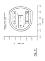
- Fig. 8 shows vector arrows which follow field lines within the cross sectional area approximately one inch from the tool face 14, with the length of each vector arrow proportional to field strength and the direction of each arrow following the field lines. It can be seen that the field B o projects radially into the formation and that it is quite uniform throughout this area, and has a substantially constant field strength of approximately 232 gauss.
- volume of greatest field homogeneity is centered about a point approximately 4/5 inch away from the wall engaging face 14
- this volume of substantially homogeneous field can be shifted either a greater or less distance into the formation, depending on the relative positioning, spacing, and field strength of magnet 25 with respect to magnets 24, 26.
- magnets 24, 25, 26 are rigidly mounted in position since the resultant positioning of the volume 9 already avoids any substantial overlap with the relatively thin mudcake layer of typical boreholes.
- the size of the Volume of Investigation 9 can depend on the nature of the measurement that is taken and the strength of a RF pulse that is transmitted by the antenna 18 as explained hereinbelow.
- the metal body 27 has, on the front face 14 thereof, a semi-cylindrically shaped cavity or slot 28 which faces formations engaged by the face 14.
- the cavity 28 is adapted for receiving the RF antenna 18, as will be further described below.
- antenna 18 is positioned outside of the metal body 27 of the tool, and is automatically shielded from electromagnetic communication with regions of the borehole which lie behind the body 27, or regions of other formations in directions intercepted by the body 27.
- Antenna 18 is thus responsive only to magnetic fields originating in front of the wall engaging face 14, e.g. fields originating in the formation 12 or in the mudcake or mud which contacts face 14 in the vicinity of the antenna 18.
- body 27 is made of metal alloy sheathing, rigidly attached to interior metal bracing, which envelops most components of the tool other than the antenna 18, including the circuitry, the magnet array 17, and the hydraulics system of the arm 15. It is also possible for the body 27 to be constructed of other combinations of materials such as composite resins, steel, etc., as long as the overall structure is sufficiently strong, and the magnetic field of the magnet array 17 can penetrate and enter the adjoining formation 12.
- Antenna 18 is used both as a RF transmitter to produce a polarizing magnetic field in formation 12, and as a receiving antenna to detect coherent magnetic signals emanating from precessing protons immediately after the polarizing field is terminated.
- Antenna 18 should be constructed of one or more current carrying loops which are highly efficient in generating magnetic fields in the formation. It is preferably made of a current loop which produces an oscillating field B 1 within the volume of investigation which is perpendicular to B o . Other current loop orientations may be useful in other embodiments of the invention having a static field B o differing from that of the preferred magnet array 17.
- Antenna 18 is attached to body 27 and fitted within the slot 28. Its efficiency can be ideally maximized when the current density within the slot 28 is made uniform. In practice, optimum antenna efficiency is difficult to achieve, because of various electromagnetic parasitic effects like the "skin effect", the mutual inductive effects between distinct current loops, and electrical effects within individual conductors.
- the preferred antenna 18 pursuant to the invention comprises a single current loop, in the shape of a trough or slot, as shown in Fig. 9.
- the antenna 18 comprises a highly conductive semi-cylindrical cavity or trough 29, end plates 30, 31, and antenna element 32 which extends from one end plate 30 to the other end plate 31, parallel to and centered in the semi-cylindrical trough 29.
- the trough 29, end plates 30, 31 and antenna element 32 are all preferably made of heavy gauge copper which has extremely low electrical resistance.
- Antenna element 32 is insulated from end plate 30 by a non-conducting bushing 33 and is connected to an electrical mounting 34 on the other side of end plate 30.
- Antenna element 32 is attached at its other end to the other end plate 31 so that current passes freely between trough 29 and antenna element 32 via end plate 31.
- Electrical mounting 34 is shown in Fig. 9 schematically as being connected to circuitry including an amplifier 35 and a detector 36. All connections in antenna 18 are brazed or silver soldered, to ensure a suitably low resistive loss.
- RF antenna 18 can be driven by amplifier 35 during specified periods of time, during which it serves as an RF antenna transmitter. Alternatively, at other specified times, antenna 18 is electronically connected to detector 36, during which time it serves as an RF receiving antenna. In certain modes of operation, antenna 18 may be called upon to alternately function as transmitter or receiver in very rapid succession.
- the space between trough 29 and antenna element 32 is preferably filled with a nonconductive material 37 having high magnetic permeability. In order to increase the antenna sensitivity Ferrite materials are preferably used.
- the relative dimensions of antenna 18 should be selected to maximize the antenna efficiency.
- the length L of the antenna may be the same as the length of the magnet array 17, which is 12 inches in the preferred embodiment, but antenna 18 is preferably about the same length as the resonance region produced by the magnet array 17 in the formation, which is approximately 4 to 8 inches long.
- the strength of the B 1 field in the sensitive volume also affects the S/N ratio (equation 12) in accordance with the term B 1 / P 1 1/2 , where B 1 is perpendicular to the static B o field.
- Fig. 13 shows a plot of the magnitude of B 1 / P 1/2 in front of a 12" trough antenna, where P 1 is the power applied to a 50 ohm impedence matching network of the antenna 18 and B1 is the circularly polarized component of the radiated field. It is seen that the field strength is quite constant at 1 inch for a longitudinal distance of about 8 inches.
- antenna 18 is installed in slot 28 and covered with a wear plate 39 made of a non-conductive abrasion resistant material to protect the ferrite material 37 as well as antenna element 32. It is preferred to additionally provide, either under or within the wear plate 39, a thin conducting wire 40 which substantially fills the antenna opening.
- the wire 40 is preferably arranged in a loop, with a spacing S between wire segments of about 1/2 inch, although this dimension can be altered if it is desired to spoil magnetic resonance in a local region of greater or lesser thickness. A small D.C.
- wire 40 constitutes one form of a means for creating localized inhomogeneous fields, and other embodiments are clearly possible. For example, multiple wires, coils,or conductive grids may be used.
- Spoiling resonance field conditions in the mudcake region is especially advantageous for the preferred embodiment shown in Figs. 1-8 because typical mudcake contains a high concentration of hydrogen nuclei which may resonate strongly with an applied RF pulse from the antenna 18.
- the mudcake lying adjacent antenna 18 is subjected to a stronger RF field B1 than even the volume of investigation 9 in formation 12, and therefore may become strongly polarized by B1 .
- B1 RF field
- the wire 40 produces a magnetic field B 2 having a high spatial gradient dB 2/ dx , and can alternatively be used to make field gradient type NMR measurements within formation 12. In this case, it would be desirable to arrange the relevant dimensions of wire 40 such that the region of measured NMR resonance overlaps with the gradient field B 2.
- the tool 13 as described measures in a single direction by preferentially directing or "focussing" both the static field B 0 and the oscillating field B 1 , to create the special Volume of Investigation 9.
- the measurement effectively excludes signals arising from within the mudcake region of the borehole.
- the measurement range (distance of sensitivity) of the tool 13 is fairly limited, it is possible to enclose the tool within a reasonably sized calibration cell during testing or calibration of the tool, to exclude magnetic effects of the environment. Consequently, the effective use of the tool 13 for logging oil wells is facilitated.
- the electronics requirements for the tool 13 may be mounted in the body 27 or in a separate cartridge or sonde.
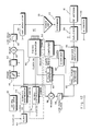
- the circuit 41 In the transmitting mode, the circuit 41 must generate a large power of about 1 kilowatt at a frequency on the order of 1 MHz. for a short precisely timed period, shut off this current very quickly, within about 10 microseconds, and then isolate any signals or noise of the power circuits from coupling with other detection circuitry within the tool 13.
- the transmitting circuitry comprises a 20 MHz. oscillator 42 and a synthesizer 43 which generates a sinusoidal signal of frequency 20 MHz. + f , where f is the desired frequency of operation of the tool. Both oscillators are linked by a clock 44 and kept in synchronization at all times.
- the output of oscillator 42 is fed to a phase shifter 45, which is controlled by a timing generator 46.
- the phase shifter 45 can produce shifts of 0, 90, 180, and 270 degrees, as desired by the operator of the tool, and in accordance with the requirements of various measurement schemes such as the Meiboom - Gill sequence.
- the phase shifted signal passes through a gate 47, and is then combined with the 20 MHz.
- the f signal which retains information of the shifted phase, is passed to the amplitude modulator 50 which adjusts the amplitude to change the signal into a desired pulse shape.
- a typical pulse fashioned by the modulator 50 and gate 47 has a first short time interval t(1) where the amplitude has been increased by the modulator 50, and a second short time interval t(2) during which the amplitude is not increased, and a third short time interval t(3) during which the amplitude is increased and the phase of the signal is reversed.
- the third period of phase reversal may not be necessary where the shaped pulse is already adequately damped by the Q-switch described hereinbelow.
- the increased amplitude during t(1) helps to decrease the time it takes to ring up the RF antenna 18, while the reversed- phase signal during t(3) helps to kill the ringing in antenna 18 at the end of the pulse. Therefore, the resultant pulse of magnetic field B 1 that is radiated into the formation 12 much more closely resembles a square pulse.
- the pulse signal from amplitude modulator 50 is amplified by power amplifier 35 which is capable of out putting approximately 1.2 kilowatts without distorting the signal shape.
- the signal then passes through an extender 53 which prevents low level noise on the order often volts or less from leaking out of amplifier 35 when it is not activated, during the receiving mode.
- the amplified pulses are then fed to the RF antenna 18, radiating a pulse of magnetic field B 1 to resonates nuclear spins in the formation. In between transmitting pulses, the RF antenna 18 receives oscillating magnetic signals of nuclear spin precession.
- the receiving system of RF probe and matching circuit is designed to have a high Q to maximize the S/N ratio.
- the antenna tends to ring for an undesirably long time, and causes undesirable magnetic spin tipping in the formation. If the antenna is permitted to ring uncontrollably, the transmitted magnetic field pulse bandwith may be substantially reduced.
- a Q switch 54 is connected to the line between extender 53 and antenna 18 as a preferred means for damping antenna ringing very quickly at the end of a transmitted pulse. The Q switch 54 closes a circuit at the appropriate time, which changes the impedence of the RF probe system (including RF antenna 18) so that the system is critically damped, and the ringing energy quickly dissipated.
- Q switch 54 is switched off, and signals from precessing nuclei are received by RF antenna 18 and passed through a duplexer 55 to a receiver amplifier 56.
- Duplexer 55 protects the receiver amplifier 56 from the high power pulses which pass from extender 53 to the RF antenna 18 during the transmitting and damping modes.
- duplexer 55 is effectively just a 50 ohm cable connecting the antenna 18 to receiver amplifier 56.
- the detected and amplified signal is then passed to a dual phase sensitive detector 57 which also receives a reference signal that controls the frequency of sensitivity of the detector 57.
- the reference signal also having frequency f , is generated by combining the 20 MHz and 20 MHz + f outputs of the oscillator 42 and synthesizer 43 in a second mixer 58, and extracting the lower frequency component f via a low pass filter 59.
- the output of low pass filter 59, a sinusoidal wave form of frequency f is used as a reference signal for both the detector 57 and a pulse generator 60.
- the pulse generator 60 generates an appropriate pulse shape in response to control and triggering signals from the computer 52, and triggers the timing generator 46.
- the detector 57 in response to the reference signal and the formation NMR signal from receiver amplifier 56, obtains a measured NMR resonance signal of frequency f from the desired volume of investigation, and passes it to the digitizer 82. The digitized signal is then forwarded to the computer 52 for processing and/or formatting as desired by the operator.
- the Q Switch 54 comprises two symmetric circuits 61 and 62, shown on the top and bottom, respectively of the figure.
- R C 1 ⁇ 2(L/C) 1 ⁇ 2.
- Q switch 54 utilizes two field effect transistors (FET's) 63, 64 connected back to back, to provide approximately the resistance of 0.36 ohms, when they are closed.
- FET's field effect transistors
- Two FET's are needed since each one is effective in developing a resistance to a high voltage therein of only one polarity due to an effective internal diode 67, and the ringing of the antenna 18 is a bipolar oscillating voltage. If the resistive value needed for critically damping an antenna 18 is greater than the resistance of the FET's 63,64, additional resistive elements may be inserted in series.
- circuitry in Fig. 16 comprise means for gating the FET's 63, 64 on and off with minimum noise being introduced into the antenna network. Since the circuits 61,62 are essentially identical, only one of them will be described below.
- a 20 nF capacitor 65 and the collector of an intermediate stage transistor 66 are charged through the line comprising diode 67, resistor 68 (51 ohms) and diode 69, where diode 67 is part of the FET 64 of the lower symmetric circuit 62.
- the base of transistor 66 is connected to an optical coupler 70 which is controlled by a signal on line 71 from the timing generator 46.
- the optical coupler 70 is preferably used with the NMR logging tool because it ensures isolation between the switching signals and the high voltage on the antenna.
- the emitter of intermediate stage transistor 66 is connected via diode 77 to the gate 72 of the FET 63.
- the gate 72 is also connected to a 1 k resistor 73 and a 8.2 nF capacitor 74, which are in turn connected to the source line 75, to constitute a R-C combination high pass filter between gate 72 and source line 75.
- This R-C filter ensures that the source-to-gate voltage never reaches excessive levels during the transmission of an RF pulse and also provides a self-turnoff time constant.
- a zener diode 76 connected in parallel with the 20 nF capacitor 65 to prevent excessively large voltages from damaging the optical coupler 70.
- a signal from the timing generator 46 is passed via line 71, to activate the optical coupler 70 and charge the base of the intermediate stage transistor 66.
- the transistor 66 is turned on, causing a voltage to be applied to gate 72, making the FET 63 conductive,and providing damping of the antenna network.
- the operator enters into the computer 52 information respecting the type of measurement sequence to be taken.
- Computer 52 sets the sequence of electronic steps needed for the equipment to implement the measurement sequence.
- the computer 52 controls the timing generator 46 which in turn sends control signals to the various components of circuit 41 to control the polarizing pulse height, length, frequency, relative phases of sequential pulses, receiving mode period and frequency, and the timing of all of the above.
- the tool 13 is capable of resonating a targeted formation 12 with many successive pulses in a short time.
- the deadtime between a transmitted pulse and the commencing of the receiving mode about 25 microseconds, is about 1000 times shorter than the deadtime of the previous commercially available logging tool.
- the pulses can have a duration of about 40 ⁇ sec. and it is possible to have as many as 1000 pulses within a measurement cycle lasting 1 second.
- a Carr-Purcell type measurement may also be made to measure the transverse relaxation time T 2 .
- This sequence is also commonly known as a 180° - 90° sequence, where the angles refer to the degree of tipping undertaken by the precessing protons during the measurement process.
- Other measurement sequences which can be undertaken with the present apparatus include the Meiboom-Gill sequence, as described in the cited Ferrar and Becker textbook, or a 90° - ⁇ - 90° sequence of the type described in G. G. McDonald and J. S.
- a prepolarizing magnet 19 is installed within the tool 13 above the position of the main magnet array 17, to magnetically polarize the formation 11 before the magnet array 17 has reached proximity to it for measurement.
- the field of the prepolarizing magnet 19 should be similar to that of the magnet array 17 in orientation, but preferably much stronger, so as to polarize a much larger population of nucleii.
- magnet array 17 comes into proximity of formation 11, and radiates it with RF pulses.
- a larger number of nuclei are aligned with the field B 0 of the magnet array 17 within the volume of substantially homogeneous field, and a correspondingly larger signal is produced.
- the prepolarization magnet is preferably an array of magnets in a configuration such as that shown in Fig. 17, comprising magnets 90, 91 92, aligned with similar poles facing in the same direction to maximize the field strength that is produced in the formation.
- magnets 90, 91 92 aligned with similar poles facing in the same direction to maximize the field strength that is produced in the formation.
- other combinations of magnets can produce a similar field, and a single magnet may be used instead of an array as shown.
- the magnetic field Bp of the prepolarizing magnet 19 can be substantially less homogeneous than the field of the magnet array 17, without adversely affecting the bandwith or S/N of the NMR measurement which depends only on the existing static field B 0 at the time of the measurement.
- the prepolarization magnet need not be constructed of the configuration of magnets as shown in Fig. 17, but may be a single magnet or some other arrangement.
- Slab magnets have been used because the slim profile tends to minimize demagnetization effects, and they are relatively easy to assemble. Since they are large and have very high energy density, the ease of handling and assembly of the magnets are significant considerations, and the simple configuration discussed herein has been found to be advantageous from many standpoints. Nevertheless, other types of magnets may be used, in accordance with the invention.
- two push-off pistons 93, 94 shown in Fig. 1 in dotted lines, may be hydraulically actuated to force the tool 13 away from the borehole wall after the arm 15 has been retracted.
- the heretofor described apparatus may be used to make measurements of nuclear magnetic resonance in formations surrounding a borehole, to determine formation characteristics such as porosity, pore size, and fluid flow permeability.
- Various methods of interpretation of NMR logging data may be used in conjunction with the disclosed apparatus.
- the FID waveform or signal 101 represents a signal measured by the prior art tool operating in either the " Continuous Mode " or the " Stationary Mode ", and the decay envelope 102 is obtained from the peak values of the FID signal. No signals are received during the "dead time" of approximately 20-30 msec. following the end of each polarizing pulse at time t o .
- Four such decay envelopes 102a, b, c, and d are shown in Fig. 21, where the FID signals 101 are measured after nonsaturating polarizing pulses having durations t pol (a), t pol (b), t pol (c) , and t pol (d) , respectively.
- the envelopes 102 of Fig. 21 show many zigzag points indicative of noise in the signal
- Fig. 20 shows a FID envelope 102 which appears smooth because it is a simplified schematic drawing not showing the effects of noise.
- each envelope 102 is fitted to an exponential decay fitting curve 103 (shown in Fig. 21) of the form where t dec is the decay time, and A 0 is the maximum amplitude of the Free Induction Decay signal at time t 0 when the polarizing pulse was initially shut off, and A(t dec ) is the measured amplitude.
- the fitting program extracts values of A 0 and T 2 * which produce the best fit, and the resulting value of A 0 represents the extrapolated ordinate axis intercept at time t dec (0) , shown in Figs. 20-21 as the points FFI .
- a preferred method of the present invention simultaneously fits the measured data to a model which integrally describes the NMR decay behavior and the changes of that behavior resulting from changes in the degree of initial polarization prior to the decay.
- This preferred method provides for the simultaneous fitting of the measured amplitudes A by minimizing a fitting quantity of the form ⁇ ⁇ [A(t pol ,t dec ) - A REPR (t pol ,t dec )]2 (B) where the representation permits the amplitude A REPR to depend on both t dec and t pol simultaneously.
- Those parameters of amplitude and T 1 in the model which give the best fit to the measured data are extracted and directly used for interpreting the data.
- the best fit is preferably obtained by a least squares type fitting computer program which performs iterative numerical minimization of the squared fitting quantity (also known as the fitting error).
- a program called "ZXSSQ" which is well known in the art and is commercially available from the IMSL Company, Houston, Texas, may be used. Because the fitting is accomplished simultaneously with respect to both the NMR decay response and the differential responses due to different initial polarizations ( t pol ), in a single step (in a "global" approach), the extracted parameters A i and T 1i are considerably more robust and less affected by signal noise.
- T 1 parameters are: where t pol is the period of polarization of the formation tending to tip the magnetic spins of the measured population of particles, before a decay signal is measured, T 1i is the longitudinal relaxation time of the i-th species or component of measured particles, and T 2i * is the observed relaxation time of the i-th species or component.
- the measured amplitudes of the FID signal 101 are represented by a sum of two exponential terms:
- the two exponent representation is based on the assumption that the formation may be regarded as containing two species of protons, each species having a distinct decay component with maximum amplitude A0 , longitudinal relaxation time T 1 and transverse relaxation time T 2 * .
- the six parameters of equation (D) are reduced to five by assuming that the value for each T 2i * is related to the corresponding T 1i through a common parameter T inh defined by:
- the parameter T inh is a time constant representing an additional decay mechanism resulting from magnetic field inhomogeneities which are common to both species of the representation.
- the representation of equation (D) is reduced to: Using this five parameter representation, it is possible to obtain relatively robust values of A S , A L and T 1S , T 1L which can then provide information of the permeability or some other desired characteristic of the measured formation. In many cases, the five parameter model fits data as well as the first model which has six parameters.
- the "stretched exponential” representation has the advantage that it can extract relaxation time parameters with comparable accuracy as the other models in some cases, but with even greater resiliency to problems arising from low Signal/Noise in the data.
- T1, T2, and/or T2* After extracting values of the relaxation times, T1, T2, and/or T2*, it is usually desirable to use these values for determining other characteristics of the measured formation, such as fluid permeability k.
- Timur has proposed the alternative estimator k ⁇ ⁇ ⁇ A i T 2 , Timur, A, " Pulsed Nuclear Magnetic Resonance Studies of Porosity, Moveable Fluid, and Permeability of Sandstones ", Journal of Petroleum Technology (1969), 775-786.
- the values of longitudinal relaxation time T 1 are preferably used in an estimator of permeability of the form k ⁇ ⁇ m T 1i n where the exponent m is approximately 4 and n is approximately 2.
- Table 2 also shows that the global methods of the invention, when used in conjunction with the preferred estimator defined herein provides considerably better determination of permeability of the measured rocks compared with the prior art methods.
- the integration method is directed to the determination of formation characteristics in situations where it is desirable to minimize the measurement time (e.g. to permit continuous logging runs). In these situations it is preferable to minimize the number of parameters to be extracted from the available data, for reasons to be explained below.
- the values of amplitude are integrated with respect to the time axis t pol to obtain a single integrated quantity having the units of ⁇ T .
- the curve 104 is integrated to obtain the area above the T 1 Build-Up curve, which is equal to the area under the corresponding decay curve.
- This integrated quantity having units equivalent to ⁇ T 1 , is then used in conjunction with an appropriate estimator to obtain a measure of permeability.
- the integrated quantity is squared to obtain ( ⁇ T 1 ) 2 , and then multiplied by ( ⁇ t ) m-2 where ⁇ t is a porosity measured by using some other known borehole logging tool such as those commonly known as neutron-porosity tools.
- Other estimators may similarly be used, as previously described.
- the integrated quantity is a more robust representation of the available low S/N data because it is less responsive to the exact shape of the curve 104, and therefore less responsive to errors which are introduced by the mathematical fitting of NMR data having significant levels of noise.
- Fig. 24 B shows an example of integration by a simple summation of separate products of the form ⁇ A i ⁇ ⁇ t pol .
- the measured NMR decay signals can be integrated with respect to decay time to obtain an integrated quantity containing information indicative of formation characteristics, which is relatively immune to signal noise or other fine features of NMR decay.
- the figures are shown with the amplitude axis scaled as the logarithm of A, and the time axis scaled linearly, the present interpretation methods are not intended to be limited to any particular presentations of data. In alternative embodiments, the methods may be implemented with altered scales for amplitude and time. For example, the time axis may be scaled as the square root or some other transformation thereof.
- the global fitting method which has been described with reference to the FID signals obtained with the prior logging tool can be equally applicable to data obtained with the pulsed NMR tool of the present invention.
- a pulsed spin-echo type measurement such as the Carr-Purcell sequence shown in Fig. 25, yields a series of pulses, the successive peaks of which define a T 2 relaxation curve. If several such sequences of measurements are made, with each sequence commencing with a different degree of initial polarization ( t pol ) , it is possible, in accordance with the present invention, to determine the longitudinal relaxation time T 1 .
- any one of the preferred representations of the global fitting method can be similarly used to extract values of amplitude and T 1 and these extracted values can then be used to determine other characteristics of the measured formation.
- the integration methods of the invention may also be used to better interpret measured signals from the new tool when it is desirable to minimize the measurement time.
- the data set has relatively low S/N, it is preferred to integrate under the echo signals, as shown in Fig. 25, and to determine the permeability in response to the obtained area in the manner already discussed above.
- the NMR logging apparatus of the present invention produces a static homogeneous magnetic field within a Volume of Investigation, as previously described, and superposes oscillating pulses of RF fields which resonantly tip the spins of protons within the Volume of Investigation.
- the tool 13 By successively imposing pulses B 1 in accordance with the Carr-Purcell sequence, the tool 13 directly measures NMR decay having T2 time constant, and is thus capable of directly measuring this formation pore fluid characteristic without the intermediary measurement of T2* decay signals, as was required of the previous logging tool.
- the Carr-Purcell sequence determining the constant of proportionality C and then continuously logging the remainder of the borehole to obtain fast measurements of T2.
- the values of T2 are transformed into T1 values by multiplying by the constant C.
- the T1 values are used in conjunction with one of the preferred methods of the invention or other comparable methods to determine the permeability of formations at each of the corresponding depths of the T2 measurements.
- T1 and T2 converge; it is thus preferred at sufficiently low measurement frequencies to equate the measured T 2 data to a hypothetical set of T 1 data, and to determine permeability by applying the measured T2 data directly to T1 estimators.
- T1 and T2 associated quantities may be similarly transformed.
- the integrated area of the Carr-Purcell sequence 105 is computed and used in place of the integrated area of the T 1 Build-Up curve to determine permeability, as previously described.
Priority Applications (10)
| Application Number | Priority Date | Filing Date | Title |
|---|---|---|---|
| US07/368,916 US4933638A (en) | 1986-08-27 | 1989-06-19 | Borehole measurement of NMR characteristics of earth formations, and interpretations thereof |
| US07/431,368 US5055787A (en) | 1986-08-27 | 1989-12-05 | Borehole measurement of NMR characteristics of earth formations |
| US07/431,256 US5055788A (en) | 1986-08-27 | 1989-12-05 | Borehole measurement of NMR characteristics of earth formations |
| US07/452,903 US5023551A (en) | 1986-08-27 | 1989-12-19 | Nuclear magnetic resonance pulse sequences for use with borehole logging tools |
| AU55111/90A AU633568B2 (en) | 1986-08-27 | 1990-05-16 | Borehole measurements of nmr characteristics of earth formations and interpretations thereof |
| DE69030204T DE69030204T2 (de) | 1986-08-27 | 1990-06-01 | Bohrlochmessung von NMR-Charakteristika von Erdformationen und Interpretation davon |
| AT94115560T ATE150181T1 (de) | 1986-08-27 | 1990-06-01 | Bohrlochmessung von nmr-charakteristika von erdformationen und interpretation davon |
| DE69018626T DE69018626T2 (de) | 1986-08-27 | 1990-06-01 | Bohrlochmessung von NMR-Charakteristika von Erdformationen und Interpretation davon. |
| EP94115560A EP0649035B1 (fr) | 1986-08-27 | 1990-06-01 | Mesure dans un puits de caractéristiques NMR de formations géologique et leur interprétation |
| DK94115560.8T DK0649035T3 (da) | 1986-08-27 | 1990-06-01 | Borehulsmåling af jordformationers NMR-egenskaber samt fortolkniger deraf |
Applications Claiming Priority (3)
| Application Number | Priority Date | Filing Date | Title |
|---|---|---|---|
| US90108486A | 1986-08-27 | 1986-08-27 | |
| US07/368,916 US4933638A (en) | 1986-08-27 | 1989-06-19 | Borehole measurement of NMR characteristics of earth formations, and interpretations thereof |
| AU55111/90A AU633568B2 (en) | 1986-08-27 | 1990-05-16 | Borehole measurements of nmr characteristics of earth formations and interpretations thereof |
Related Child Applications (1)
| Application Number | Title | Priority Date | Filing Date |
|---|---|---|---|
| EP94115560.8 Division-Into | 1994-10-04 |
Publications (2)
| Publication Number | Publication Date |
|---|---|
| EP0459064A1 true EP0459064A1 (fr) | 1991-12-04 |
| EP0459064B1 EP0459064B1 (fr) | 1995-04-12 |
Family
ID=27154976
Family Applications (2)
| Application Number | Title | Priority Date | Filing Date |
|---|---|---|---|
| EP90401475A Expired - Lifetime EP0459064B1 (fr) | 1986-08-27 | 1990-06-01 | Mesure dans un puits de caractéristiques NMR de formations géologique et leur interprétation |
| EP94115560A Expired - Lifetime EP0649035B1 (fr) | 1986-08-27 | 1990-06-01 | Mesure dans un puits de caractéristiques NMR de formations géologique et leur interprétation |
Family Applications After (1)
| Application Number | Title | Priority Date | Filing Date |
|---|---|---|---|
| EP94115560A Expired - Lifetime EP0649035B1 (fr) | 1986-08-27 | 1990-06-01 | Mesure dans un puits de caractéristiques NMR de formations géologique et leur interprétation |
Country Status (6)
| Country | Link |
|---|---|
| US (1) | US4933638A (fr) |
| EP (2) | EP0459064B1 (fr) |
| AT (2) | ATE121198T1 (fr) |
| AU (1) | AU633568B2 (fr) |
| DE (2) | DE69018626T2 (fr) |
| DK (2) | DK0649035T3 (fr) |
Cited By (5)
| Publication number | Priority date | Publication date | Assignee | Title |
|---|---|---|---|---|
| EP0687919A1 (fr) * | 1994-06-15 | 1995-12-20 | Oxford Instruments (Uk) Limited | Ensemble d'aimants |
| WO2003098248A3 (fr) * | 2002-05-17 | 2005-06-09 | Medi Physics Inc | Procedes, systemes, circuits et progiciels pour la determination de la polarisation d'un gaz |
| WO2006064264A1 (fr) * | 2004-12-16 | 2006-06-22 | King's College London | Procede et appareil pour essai nqr |
| CN103353462A (zh) * | 2013-06-17 | 2013-10-16 | 中国石油大学(华东) | 一种基于核磁共振成像的岩石非均质性定量评价方法 |
| WO2018102362A1 (fr) * | 2016-11-29 | 2018-06-07 | Schlumberger Canada Limited | Instrument et procédé de diagraphie de puits rmn comportant des ouvertures synthétiques |
Families Citing this family (103)
| Publication number | Priority date | Publication date | Assignee | Title |
|---|---|---|---|---|
| US4933638A (en) * | 1986-08-27 | 1990-06-12 | Schlumber Technology Corp. | Borehole measurement of NMR characteristics of earth formations, and interpretations thereof |
| EP0560893B1 (fr) * | 1990-12-05 | 1996-11-20 | Numar Corporation | Systeme de diagraphie nmr d'un puits pendant son forage |
| US5153514A (en) * | 1991-02-19 | 1992-10-06 | Schlumberger Technology Corp. | Antenna and wear plates for borehole logging apparatus |
| US5412320A (en) * | 1991-05-16 | 1995-05-02 | Numar Corporation | Nuclear magnetic resonance determination of petrophysical properties of geologic structures |
| US5309098A (en) * | 1991-05-16 | 1994-05-03 | Numar Corporation | Nuclear magnetic resonance detection of geologic structures |
| MX9202314A (es) * | 1991-05-16 | 1992-11-01 | Numar Corp | Deteccion por resonancia magnetica nuclear de estructuras geologicas. |
| US5557200A (en) * | 1991-05-16 | 1996-09-17 | Numar Corporation | Nuclear magnetic resonance determination of petrophysical properties of geologic structures |
| US5289124A (en) * | 1991-09-20 | 1994-02-22 | Exxon Research And Engineering Company | Permeability determination from NMR relaxation measurements for fluids in porous media |
| US5387865A (en) * | 1991-09-20 | 1995-02-07 | Exxon Research And Engineering Company | Permeability determination from NMR relaxation measurements for fluids in porous media |
| US5389877A (en) * | 1991-11-27 | 1995-02-14 | Schlumberger Technology Corporation | Nuclear magnetic resonance pulse sequences for determining bound fluid volume |
| DK0581666T3 (da) * | 1992-07-30 | 1997-10-27 | Schlumberger Ltd | Impulsmoduleret kernemagnetisk værktøj til formationsevaluering under boring |
| US5923167A (en) * | 1992-07-30 | 1999-07-13 | Schlumberger Technology Corporation | Pulsed nuclear magnetism tool for formation evaluation while drilling |
| US5629623A (en) * | 1992-07-30 | 1997-05-13 | Schlumberger Technology Corporation | Pulsed nuclear magnetism tool for formation evaluation while drilling |
| US5432446A (en) * | 1992-11-02 | 1995-07-11 | Schlumberger Technology Corporation | Borehole measurement of NMR characteristics of earth formation |
| US5486762A (en) * | 1992-11-02 | 1996-01-23 | Schlumberger Technology Corp. | Apparatus including multi-wait time pulsed NMR logging method for determining accurate T2-distributions and accurate T1/T2 ratios and generating a more accurate output record using the updated T2-distributions and T1/T2 ratios |
| US5291137A (en) * | 1992-11-02 | 1994-03-01 | Schlumberger Technology Corporation | Processing method and apparatus for processing spin echo in-phase and quadrature amplitudes from a pulsed nuclear magnetism tool and producing new output data to be recorded on an output record |
| US5363041A (en) * | 1992-12-31 | 1994-11-08 | Schlumberger Technology Corporation | Determining bound and unbound fluid volumes using nuclear magnetic resonance pulse sequences |
| US5596274A (en) * | 1992-12-31 | 1997-01-21 | Schlumberger Technology Corporation | Determining bound and unbound fluid volumes using nuclear magnetic resonance pulse sequences |
| US5376884A (en) * | 1993-04-01 | 1994-12-27 | Schlumberger Technology Corporation | Nuclear magnetic resonance measuring apparatus |
| US5339035A (en) * | 1993-05-07 | 1994-08-16 | General Electric Company | MR imaging with rectangular magnetization transfer pulse |
| FR2710780B1 (fr) * | 1993-09-30 | 1995-10-27 | Commissariat Energie Atomique | Structures magnétiques ouvertes. |
| FR2729228A1 (fr) * | 1995-01-10 | 1996-07-12 | Commissariat Energie Atomique | Procede de determination de la porosite et de la permeabilite de formations geologiques et dispositif pour la mise en oeuvre de ce procede |
| US5680043A (en) * | 1995-03-23 | 1997-10-21 | Schlumberger Technology Corporation | Nuclear magnetic resonance technique for determining gas effect with borehole logging tools |
| US5696448A (en) * | 1995-06-26 | 1997-12-09 | Numar Corporation | NMR system and method for formation evaluation using diffusion and relaxation log measurements |
| US5936405A (en) * | 1995-09-25 | 1999-08-10 | Numar Corporation | System and method for lithology-independent gas detection using multifrequency gradient NMR logging |
| US6242912B1 (en) | 1995-10-12 | 2001-06-05 | Numar Corporation | System and method for lithology-independent gas detection using multifrequency gradient NMR logging |
| US6512371B2 (en) | 1995-10-12 | 2003-01-28 | Halliburton Energy Services, Inc. | System and method for determining oil, water and gas saturations for low-field gradient NMR logging tools |
| US6956371B2 (en) * | 1995-10-12 | 2005-10-18 | Halliburton Energy Services, Inc. | Method and apparatus for detecting diffusion sensitive phases with estimation of residual error in NMR logs |
| US5815076A (en) * | 1996-01-16 | 1998-09-29 | Sensormatic Electronics Corporation | Pulsed-signal magnetomechanical electronic article surveillance system with improved damping of transmitting antenna |
| GB2352819B (en) * | 1996-02-23 | 2001-03-28 | Western Atlas Int Inc | Nuclear magnetic resonance apparatus and method |
| US5712566A (en) * | 1996-02-23 | 1998-01-27 | Western Atlas International, Inc. | Nuclear magnetic resonance apparatus and method |
| US5644231A (en) * | 1996-03-04 | 1997-07-01 | Schlumberger Technology Corporation | High pressure magnetic antenna assembly |
| MY122012A (en) * | 1996-03-14 | 2006-03-31 | Shell Int Research | Determining a fluid fraction in an earth formation |
| US6005389A (en) * | 1996-03-15 | 1999-12-21 | Numar Corporation | Pulse sequences and interpretation techniques for NMR measurements |
| US5831433A (en) * | 1996-12-04 | 1998-11-03 | Sezginer; Abdurrahman | Well logging method and apparatus for NMR and resistivity measurements |
| US6531868B2 (en) | 1996-12-30 | 2003-03-11 | Halliburton Energy Services, Inc. | System and methods for formation evaluation while drilling |
| US6051973A (en) * | 1996-12-30 | 2000-04-18 | Numar Corporation | Method for formation evaluation while drilling |
| US6204663B1 (en) | 1997-03-26 | 2001-03-20 | Numar Corporation | Pulse sequence and method for suppression of magneto-acoustic artifacts in NMR data |
| US6032101A (en) * | 1997-04-09 | 2000-02-29 | Schlumberger Technology Corporation | Methods for evaluating formations using NMR and other logs |
| GB2325981B (en) * | 1997-04-21 | 2002-04-10 | Baker Hughes Inc | Nuclear magnetic resonance apparatus and method for geological applications |
| US6177794B1 (en) | 1997-05-13 | 2001-01-23 | The Regents Of The University Of California | Use of earth field spin echo NMR to search for liquid minerals |
| US5977768A (en) * | 1997-06-23 | 1999-11-02 | Schlumberger Technology Corporation | Nuclear magnetic resonance logging with azimuthal resolution |
| US6255817B1 (en) | 1997-06-23 | 2001-07-03 | Schlumberger Technology Corporation | Nuclear magnetic resonance logging with azimuthal resolution |
| US6166540A (en) | 1997-06-30 | 2000-12-26 | Wollin Ventures, Inc. | Method of resistivity well logging utilizing nuclear magnetic resonance |
| US6040696A (en) * | 1997-09-16 | 2000-03-21 | Schlumberger Technology Corporation | Method for estimating pore structure in carbonates from NMR measurements |
| US6166543A (en) * | 1997-09-25 | 2000-12-26 | Schlumberger Technology Corporation | Method and apparatus for measuring nuclear magnetic resonance |
| US6049205A (en) * | 1997-10-01 | 2000-04-11 | Western Atlas International, Inc. | Multiple frequency method for nuclear magnetic resonance longitudinal relaxation measurement and pulsing sequence for power use optimization |
| US6111408A (en) * | 1997-12-23 | 2000-08-29 | Numar Corporation | Nuclear magnetic resonance sensing apparatus and techniques for downhole measurements |
| DE69939252D1 (de) * | 1998-01-16 | 2008-09-18 | Halliburton Energy Serv Inc | Verfahren und anordnung zur kernmagnetischen messung während des bohrens |
| US6023164A (en) * | 1998-02-20 | 2000-02-08 | Numar Corporation | Eccentric NMR well logging apparatus and method |
| US6559639B2 (en) | 1998-10-02 | 2003-05-06 | Schlumberger Technology Corporation | Estimating permeability without determinating a distribution of relaxation times |
| US6107796A (en) * | 1998-08-17 | 2000-08-22 | Numar Corporation | Method and apparatus for differentiating oil based mud filtrate from connate oil |
| US6255818B1 (en) | 1998-08-18 | 2001-07-03 | Schlumberger Technology Corporation | Method and apparatus for performing magnetic resonance measurements |
| US6377042B1 (en) | 1998-08-31 | 2002-04-23 | Numar Corporation | Method and apparatus for merging of NMR echo trains in the time domain |
| US6140818A (en) * | 1998-10-19 | 2000-10-31 | Schlumberger Technology Corporation | NMR logging tool and method for fast logging |
| US6225803B1 (en) * | 1998-10-29 | 2001-05-01 | Baker Hughes Incorporated | NMR log processing using wavelet filter and iterative inversion |
| US6366087B1 (en) | 1998-10-30 | 2002-04-02 | George Richard Coates | NMR logging apparatus and methods for fluid typing |
| US6114851A (en) * | 1999-02-12 | 2000-09-05 | Baker Hughes Incorporated | Temperature compensated nuclear magnetic resonance apparatus and method |
| US6316940B1 (en) | 1999-03-17 | 2001-11-13 | Numar Corporation | System and method for identification of hydrocarbons using enhanced diffusion |
| US6489872B1 (en) | 1999-05-06 | 2002-12-03 | New Mexico Resonance | Unilateral magnet having a remote uniform field region for nuclear magnetic resonance |
| US6411087B1 (en) | 1999-05-17 | 2002-06-25 | University Of Houston | NMR logging tool with Hi-Tc trap field magnet |
| US6661226B1 (en) | 1999-08-13 | 2003-12-09 | Halliburton Energy Services, Inc. | NMR apparatus and methods for measuring volumes of hydrocarbon gas and oil |
| US6255819B1 (en) | 1999-10-25 | 2001-07-03 | Halliburton Energy Services, Inc. | System and method for geologically-enhanced magnetic resonance imaging logs |
| US6541969B2 (en) | 1999-12-15 | 2003-04-01 | Halliburton Energy Services, Inc. | Method and apparatus for improving the vertical resolution of NMR logs |
| US6459263B2 (en) * | 2000-02-08 | 2002-10-01 | Baker Hughes Incorporated | Nuclear magnetic resonance measurements in well logging using motion triggered pulsing |
| US6445187B1 (en) | 2000-04-10 | 2002-09-03 | Jerry R. Montgomery | System for the measurement of electrical characteristics of geological formations from within steel cased wells using magnetic circuits |
| US6445180B1 (en) * | 2000-06-28 | 2002-09-03 | Baker Hughes Incorporated | Nuclear magnetic resonance tool with active RF spoiler antenna |
| US6577125B2 (en) | 2000-12-18 | 2003-06-10 | Halliburton Energy Services, Inc. | Temperature compensated magnetic field apparatus for NMR measurements |
| US6940378B2 (en) | 2001-01-19 | 2005-09-06 | Halliburton Energy Services | Apparatus and method for magnetic resonance measurements in an interior volume |
| US7135862B2 (en) | 2001-03-13 | 2006-11-14 | Halliburton Energy Services, Inc | NMR logging using time-domain averaging |
| US6686738B2 (en) * | 2001-04-17 | 2004-02-03 | Baker Hughes Incorporated | Method for determining decay characteristics of multi-component downhole decay data |
| US6518756B1 (en) * | 2001-06-14 | 2003-02-11 | Halliburton Energy Services, Inc. | Systems and methods for determining motion tool parameters in borehole logging |
| US6525534B2 (en) | 2001-06-15 | 2003-02-25 | Halliburton Energy Services, Inc. | System and methods for NMR signal processing without phase alternated pair stacking |
| US6984980B2 (en) * | 2002-02-14 | 2006-01-10 | Baker Hughes Incorporated | Method and apparatus for NMR sensor with loop-gap resonator |
| AU2003267080A1 (en) * | 2002-09-11 | 2004-04-30 | Halliburton Energy Services, Inc. | Nmr tool with helical polarization |
| EP1642156B1 (fr) | 2003-05-02 | 2020-03-04 | Halliburton Energy Services, Inc. | Systemes et procedes pour la diagraphie par resonance magnetique nucleaire |
| WO2005036208A2 (fr) | 2003-10-03 | 2005-04-21 | Halliburton Energy Services, Inc. | Systeme et procedes de diagraphie a base t1 |
| WO2005067569A2 (fr) * | 2004-01-04 | 2005-07-28 | Halliburton Energy Services, Inc. | Procede et appareil de detection d'hydrocarbures avec des diagraphies rmn dans des puits fores avec des boues a base d'huile |
| US7221158B1 (en) | 2005-12-12 | 2007-05-22 | Schlumberger Technology Corporation | Permeability determinations from nuclear magnetic resonance measurements |
| US7742008B2 (en) * | 2006-11-15 | 2010-06-22 | Baker Hughes Incorporated | Multipole antennae for logging-while-drilling resistivity measurements |
| US8185314B2 (en) | 2007-02-13 | 2012-05-22 | Schlumberger Technology Corporation | Method and system for determining dynamic permeability of gas hydrate saturated formations |
| US20090322324A1 (en) * | 2007-05-04 | 2009-12-31 | Penanen Konstantin I | Geometries for superconducting sensing coils for squid-based systems |
| EP2142090A4 (fr) * | 2007-05-04 | 2011-07-20 | California Inst Of Techn | Dispositifs mri squid à faible champ, composants et procédés |
| US7502691B2 (en) * | 2007-07-31 | 2009-03-10 | Baker Hughes Incorporated | Method and computer program product for determining a degree of similarity between well log data |
| US7753118B2 (en) * | 2008-04-04 | 2010-07-13 | Schlumberger Technology Corporation | Method and tool for evaluating fluid dynamic properties of a cement annulus surrounding a casing |
| US7753117B2 (en) * | 2008-04-04 | 2010-07-13 | Schlumberger Technology Corporation | Tool and method for evaluating fluid dynamic properties of a cement annulus surrounding a casing |
| CA2753347C (fr) | 2009-03-02 | 2017-09-26 | Statoil Asa | Methode d'ajustement des proprietes de fluides de forage et appareil servant a de telles methodes |
| WO2012170014A1 (fr) | 2011-06-07 | 2012-12-13 | Halliburton Energy Services, Inc. | Indexage en rotation pour optimiser le volume de détection d'un outil de diagraphie par résonance magnétique nucléaire |
| US9121966B2 (en) | 2011-11-28 | 2015-09-01 | Baker Hughes Incorporated | Media displacement device and method of improving transfer of electromagnetic energy between a tool and an earth formation |
| US20130181706A1 (en) * | 2012-01-18 | 2013-07-18 | Baker Hughes Incorporated | System and method to estimate a property of a fluid flow |
| US9423365B2 (en) * | 2012-04-04 | 2016-08-23 | Schlumberger Technology Corporation | T2-cutoff determination using magnetic susceptibility measurements |
| US10633969B2 (en) * | 2013-08-01 | 2020-04-28 | Conocophillips Company | Dynamic in-situ measurement of reservoir wettability |
| US10197696B2 (en) | 2013-11-15 | 2019-02-05 | Baker Hughes, A Ge Company, Llc | NMR logging interpretation of solid invasion |
| US11300531B2 (en) | 2014-06-25 | 2022-04-12 | Aspect Ai Ltd. | Accurate water cut measurement |
| US10197564B2 (en) | 2014-07-25 | 2019-02-05 | Gersh Z. Taicher | Nuclear magnetic resonance apparatus and methods |
| US10094897B2 (en) | 2014-07-25 | 2018-10-09 | Gersh Z. Taicher | Nuclear magnetic resonance apparatus and methods |
| US9964501B2 (en) | 2014-11-05 | 2018-05-08 | Gersh Z. Taicher | Nuclear magnetic resonance apparatus and methods |
| US9817094B2 (en) | 2014-11-05 | 2017-11-14 | Gersh Z. Taicher | Nuclear magnetic resonance apparatus and methods |
| EP3183423A4 (fr) * | 2014-11-12 | 2018-05-16 | Halliburton Energy Services, Inc. | Réduction de signaux de trou de forage pour un outil de diagraphie à rmn à orientation latérale à l'aide d'une antenne |
| BR112018001149A2 (pt) * | 2015-08-13 | 2018-09-18 | Halliburton Energy Services Inc | circuito, sistema e método |
| US10228336B2 (en) * | 2015-09-01 | 2019-03-12 | Chevron U.S.A. Inc. | Mobile NMR sensor for analyzing subsurface samples |
| US10345251B2 (en) | 2017-02-23 | 2019-07-09 | Aspect Imaging Ltd. | Portable NMR device for detecting an oil concentration in water |
| US11650347B2 (en) | 2017-05-24 | 2023-05-16 | Schlumberger Technology Corporation | Fast measurement and interpretation of downhole multi-dimensional measurement |
Citations (4)
| Publication number | Priority date | Publication date | Assignee | Title |
|---|---|---|---|---|
| US3289072A (en) * | 1953-01-13 | 1966-11-29 | Schlumberger Well Surv Corp | Analysis of substances by measurement of nuclear magnetic relaxation times |
| US4646022A (en) * | 1985-07-31 | 1987-02-24 | Chevron Research Company | Computer-linked nuclear magnetic logging tool and method having a sham polarizing cycle for rapidly dispersing components of residual polarization associated with a prior-in-time NML collection cycle |
| US4714881A (en) * | 1986-07-15 | 1987-12-22 | Mobil Oil Corporation | Nuclear magnetic resonance borehole logging tool |
| US4717878A (en) * | 1986-09-26 | 1988-01-05 | Numar Corporation | Nuclear magnetic resonance sensing apparatus and techniques |
Family Cites Families (15)
| Publication number | Priority date | Publication date | Assignee | Title |
|---|---|---|---|---|
| US3528000A (en) * | 1954-03-05 | 1970-09-08 | Schlumberger Well Surv Corp | Nuclear resonance well logging method and apparatus |
| US3083335A (en) * | 1955-10-05 | 1963-03-26 | Schlumberger Well Surv Corp | Magnetic resonance methods and apparatus |
| US3597681A (en) * | 1957-01-30 | 1971-08-03 | Chevron Res | Nuclear magnetic well logging |
| US3042855A (en) * | 1957-11-22 | 1962-07-03 | California Research Corp | Method of and apparatus for reducing remnant magnetic fields in nuclear magnetism well logging |
| FR1475608A (fr) * | 1964-04-30 | 1967-04-07 | Inst Francais Du Petrole | Procédé de détection des hydrocarbures |
| US3483465A (en) * | 1966-03-25 | 1969-12-09 | Schlumberger Technology Corp | Nuclear magnetism logging system utilizing an oscillated polarizing field |
| US3538429A (en) * | 1966-12-01 | 1970-11-03 | Schlumberger Technology Corp | Coil assembly for nuclear magnetism well logging |
| US3508438A (en) * | 1967-06-27 | 1970-04-28 | Schlumberger Technology Corp | Well logging apparatus and method |
| US3667035A (en) * | 1970-03-17 | 1972-05-30 | Texaco Development Corp | Nuclear magnetism logging |
| US4350955A (en) * | 1980-10-10 | 1982-09-21 | The United States Of America As Represented By The United States Department Of Energy | Magnetic resonance apparatus |
| US4528508A (en) * | 1982-06-10 | 1985-07-09 | Paramagnetic Logging, Inc. | Nuclear magnetic resonance method and apparatus for remote detection and volumetric measurement of petroleum reserves |
| GB2141236B (en) * | 1983-06-09 | 1986-12-10 | Nat Res Dev | Nuclear magnetic logging |
| GB8315866D0 (en) * | 1983-06-09 | 1983-07-13 | Nat Res Dev | Nuclear magnetic logging |
| AU583820B2 (en) * | 1985-04-26 | 1989-05-11 | Schlumberger Technology B.V. | Induction logging sonde with metallic support |
| US4933638A (en) * | 1986-08-27 | 1990-06-12 | Schlumber Technology Corp. | Borehole measurement of NMR characteristics of earth formations, and interpretations thereof |
-
1989
- 1989-06-19 US US07/368,916 patent/US4933638A/en not_active Expired - Lifetime
-
1990
- 1990-05-16 AU AU55111/90A patent/AU633568B2/en not_active Expired
- 1990-06-01 DE DE69018626T patent/DE69018626T2/de not_active Expired - Lifetime
- 1990-06-01 EP EP90401475A patent/EP0459064B1/fr not_active Expired - Lifetime
- 1990-06-01 DE DE69030204T patent/DE69030204T2/de not_active Expired - Lifetime
- 1990-06-01 AT AT90401475T patent/ATE121198T1/de not_active IP Right Cessation
- 1990-06-01 AT AT94115560T patent/ATE150181T1/de not_active IP Right Cessation
- 1990-06-01 EP EP94115560A patent/EP0649035B1/fr not_active Expired - Lifetime
- 1990-06-01 DK DK94115560.8T patent/DK0649035T3/da active
- 1990-06-01 DK DK90401475.0T patent/DK0459064T3/da active
Patent Citations (4)
| Publication number | Priority date | Publication date | Assignee | Title |
|---|---|---|---|---|
| US3289072A (en) * | 1953-01-13 | 1966-11-29 | Schlumberger Well Surv Corp | Analysis of substances by measurement of nuclear magnetic relaxation times |
| US4646022A (en) * | 1985-07-31 | 1987-02-24 | Chevron Research Company | Computer-linked nuclear magnetic logging tool and method having a sham polarizing cycle for rapidly dispersing components of residual polarization associated with a prior-in-time NML collection cycle |
| US4714881A (en) * | 1986-07-15 | 1987-12-22 | Mobil Oil Corporation | Nuclear magnetic resonance borehole logging tool |
| US4717878A (en) * | 1986-09-26 | 1988-01-05 | Numar Corporation | Nuclear magnetic resonance sensing apparatus and techniques |
Non-Patent Citations (2)
| Title |
|---|
| 54TH ANNUAL FALL TECHNICAL CONFERENCE AND EXHIBITION OF THE SOCIETY OF PETROLEUM ENGINEERS (AIME, Dallas, Texas), Las Vegas, 1979, pages 1-8; R.C. HERRICK et al.: "An improved nuclear magnetism logging system and its application to formation evaluation" * |
| 61ST ANNUAL FALL TECHNICAL CONFERENCE AND EXHIBITION OF THE SOCIETY OF PETROLEUM ENGINEERS, New Orleans, LA, 5th - 8th October 1986, pages 1-22, Society of Petroleum Engineers, US; W.E. KENYON et al.: "Compact and consistent representation of rock NMR data for permeability estimation" * |
Cited By (8)
| Publication number | Priority date | Publication date | Assignee | Title |
|---|---|---|---|---|
| EP0687919A1 (fr) * | 1994-06-15 | 1995-12-20 | Oxford Instruments (Uk) Limited | Ensemble d'aimants |
| WO2003098248A3 (fr) * | 2002-05-17 | 2005-06-09 | Medi Physics Inc | Procedes, systemes, circuits et progiciels pour la determination de la polarisation d'un gaz |
| US7275413B2 (en) | 2002-05-17 | 2007-10-02 | Medi-Physics, Inc. | Methods, systems, circuits, and computer program products for determining polarization of a gas |
| WO2006064264A1 (fr) * | 2004-12-16 | 2006-06-22 | King's College London | Procede et appareil pour essai nqr |
| CN103353462A (zh) * | 2013-06-17 | 2013-10-16 | 中国石油大学(华东) | 一种基于核磁共振成像的岩石非均质性定量评价方法 |
| CN103353462B (zh) * | 2013-06-17 | 2015-12-09 | 中国石油大学(华东) | 一种基于核磁共振成像的岩石非均质性定量评价方法 |
| WO2018102362A1 (fr) * | 2016-11-29 | 2018-06-07 | Schlumberger Canada Limited | Instrument et procédé de diagraphie de puits rmn comportant des ouvertures synthétiques |
| US10444397B2 (en) | 2016-11-29 | 2019-10-15 | Schlumberger Technology Corporation | NMR well logging instrument and method with synthetic apertures |
Also Published As
| Publication number | Publication date |
|---|---|
| ATE150181T1 (de) | 1997-03-15 |
| AU633568B2 (en) | 1993-02-04 |
| EP0649035B1 (fr) | 1997-03-12 |
| DE69018626T2 (de) | 1995-12-14 |
| DK0459064T3 (da) | 1995-07-24 |
| DE69030204T2 (de) | 1997-10-09 |
| ATE121198T1 (de) | 1995-04-15 |
| EP0649035A1 (fr) | 1995-04-19 |
| DE69018626D1 (de) | 1995-05-18 |
| AU5511190A (en) | 1992-04-02 |
| DE69030204D1 (de) | 1997-04-17 |
| US4933638A (en) | 1990-06-12 |
| DK0649035T3 (da) | 1997-06-30 |
| EP0459064B1 (fr) | 1995-04-12 |
Similar Documents
| Publication | Publication Date | Title |
|---|---|---|
| EP0459064B1 (fr) | Mesure dans un puits de caractéristiques NMR de formations géologique et leur interprétation | |
| US5055787A (en) | Borehole measurement of NMR characteristics of earth formations | |
| CA2172424C (fr) | Methode de diagraphie de forage a resonance magnetique nucleaire, et appareil connexe | |
| EP0967490B1 (fr) | Procédé pour éliminer l'oscillation après l'impulsion pendant une mesure de RMN dans un puits | |
| US7511487B2 (en) | Logging method for determining characteristic of fluid in a downhole measurement region | |
| US6459262B1 (en) | Toroidal receiver for NMR MWD | |
| US4350955A (en) | Magnetic resonance apparatus | |
| US6344744B2 (en) | Multiple frequency method for nuclear magnetic resonance longitudinal relaxation measurement and pulsing sequence for power use optimization | |
| US6342784B1 (en) | Method for resistivity well logging utilizing nuclear magnetic resonance | |
| US5814988A (en) | Combination nuclear magnetic resonance and electromagnetic induction resistivity well logging instrument and method | |
| CA2230908C (fr) | Methode et dispositif de diagraphie rmn longitudinale | |
| US6023163A (en) | Well logging method and apparatus for determining gas and diffusion coefficient using NMR | |
| WO2002050573A1 (fr) | Circuit magnetique a compensation de temperature | |
| US6177794B1 (en) | Use of earth field spin echo NMR to search for liquid minerals | |
| US6388441B1 (en) | Method for processing NMR data without phase-alternating-pair (PAP) averaging | |
| US6097184A (en) | Nuclear magnetic resonance well logging to determine gas-filled porosity and oil-filled porosity of earth formations without a constant static magnetic field gradient | |
| US6518755B2 (en) | Measurement technique and apparatus for high-resolution multi-volume NMR well logging | |
| Taicher et al. | A comprehensive approach to studies of porous media (rocks) using a laboratory spectrometer and logging tool with similar operating characteristics | |
| JP2545484B2 (ja) | 地層のnmr特性の穿孔測定及びその解釈 | |
| IE901752A1 (en) | Borehole measurement of NMR characteristics of earth formations, and interpretations thereof | |
| Jackson et al. | Magnetic resonance apparatus | |
| Tool | NMR logging tools | |
| NO300475B1 (no) | Borehullsmåling av NMR-egenskaper ved bergartsformasjoner | |
| MXPA99009936A (en) | Apparatus and method for calculating a spin-es relaxation time distribution |
Legal Events
| Date | Code | Title | Description |
|---|---|---|---|
| PUAI | Public reference made under article 153(3) epc to a published international application that has entered the european phase |
Free format text: ORIGINAL CODE: 0009012 |
|
| AK | Designated contracting states |
Kind code of ref document: A1 Designated state(s): AT DE DK FR GB IT NL |
|
| 17P | Request for examination filed |
Effective date: 19920527 |
|
| 17Q | First examination report despatched |
Effective date: 19930513 |
|
| GRAA | (expected) grant |
Free format text: ORIGINAL CODE: 0009210 |
|
| ITF | It: translation for a ep patent filed |
Owner name: DOTT. FRANCO CICOGNA |
|
| AK | Designated contracting states |
Kind code of ref document: B1 Designated state(s): AT DE DK FR GB IT NL |
|
| PG25 | Lapsed in a contracting state [announced via postgrant information from national office to epo] |
Ref country code: AT Effective date: 19950412 |
|
| REF | Corresponds to: |
Ref document number: 121198 Country of ref document: AT Date of ref document: 19950415 Kind code of ref document: T |
|
| XX | Miscellaneous (additional remarks) |
Free format text: TEILANMELDUNG 94115560.8 EINGEREICHT AM 01/06/90. |
|
| REF | Corresponds to: |
Ref document number: 69018626 Country of ref document: DE Date of ref document: 19950518 |
|
| REG | Reference to a national code |
Ref country code: DK Ref legal event code: T3 |
|
| ET | Fr: translation filed | ||
| PLBE | No opposition filed within time limit |
Free format text: ORIGINAL CODE: 0009261 |
|
| STAA | Information on the status of an ep patent application or granted ep patent |
Free format text: STATUS: NO OPPOSITION FILED WITHIN TIME LIMIT |
|
| 26N | No opposition filed | ||
| REG | Reference to a national code |
Ref country code: GB Ref legal event code: IF02 |
|
| PGFP | Annual fee paid to national office [announced via postgrant information from national office to epo] |
Ref country code: GB Payment date: 20030528 Year of fee payment: 14 |
|
| PGFP | Annual fee paid to national office [announced via postgrant information from national office to epo] |
Ref country code: FR Payment date: 20030610 Year of fee payment: 14 |
|
| PGFP | Annual fee paid to national office [announced via postgrant information from national office to epo] |
Ref country code: NL Payment date: 20030630 Year of fee payment: 14 |
|
| PG25 | Lapsed in a contracting state [announced via postgrant information from national office to epo] |
Ref country code: GB Free format text: LAPSE BECAUSE OF NON-PAYMENT OF DUE FEES Effective date: 20040601 |
|
| PG25 | Lapsed in a contracting state [announced via postgrant information from national office to epo] |
Ref country code: NL Free format text: LAPSE BECAUSE OF NON-PAYMENT OF DUE FEES Effective date: 20050101 |
|
| GBPC | Gb: european patent ceased through non-payment of renewal fee | ||
| PG25 | Lapsed in a contracting state [announced via postgrant information from national office to epo] |
Ref country code: FR Free format text: LAPSE BECAUSE OF NON-PAYMENT OF DUE FEES Effective date: 20050228 |
|
| NLV4 | Nl: lapsed or anulled due to non-payment of the annual fee |
Effective date: 20050101 |
|
| REG | Reference to a national code |
Ref country code: FR Ref legal event code: ST |
|
| PG25 | Lapsed in a contracting state [announced via postgrant information from national office to epo] |
Ref country code: IT Free format text: LAPSE BECAUSE OF NON-PAYMENT OF DUE FEES Effective date: 20050601 |
|
| PGFP | Annual fee paid to national office [announced via postgrant information from national office to epo] |
Ref country code: DK Payment date: 20090615 Year of fee payment: 20 |
|
| PGFP | Annual fee paid to national office [announced via postgrant information from national office to epo] |
Ref country code: DE Payment date: 20090529 Year of fee payment: 20 |
|
| REG | Reference to a national code |
Ref country code: DK Ref legal event code: EUP |
|
| PG25 | Lapsed in a contracting state [announced via postgrant information from national office to epo] |
Ref country code: DE Free format text: LAPSE BECAUSE OF EXPIRATION OF PROTECTION Effective date: 20100601 |