EP0458670B1 - Method of pneumatic fuel injection in a two-stroke engine and such a two-stroke engine - Google Patents
Method of pneumatic fuel injection in a two-stroke engine and such a two-stroke engine Download PDFInfo
- Publication number
- EP0458670B1 EP0458670B1 EP91401184A EP91401184A EP0458670B1 EP 0458670 B1 EP0458670 B1 EP 0458670B1 EP 91401184 A EP91401184 A EP 91401184A EP 91401184 A EP91401184 A EP 91401184A EP 0458670 B1 EP0458670 B1 EP 0458670B1
- Authority
- EP
- European Patent Office
- Prior art keywords
- engine
- injection
- chamber
- accordance
- cylinder
- Prior art date
- Legal status (The legal status is an assumption and is not a legal conclusion. Google has not performed a legal analysis and makes no representation as to the accuracy of the status listed.)
- Expired - Lifetime
Links
Images


Classifications
-
- F—MECHANICAL ENGINEERING; LIGHTING; HEATING; WEAPONS; BLASTING
- F02—COMBUSTION ENGINES; HOT-GAS OR COMBUSTION-PRODUCT ENGINE PLANTS
- F02M—SUPPLYING COMBUSTION ENGINES IN GENERAL WITH COMBUSTIBLE MIXTURES OR CONSTITUENTS THEREOF
- F02M67/00—Apparatus in which fuel-injection is effected by means of high-pressure gas, the gas carrying the fuel into working cylinders of the engine, e.g. air-injection type
- F02M67/02—Apparatus in which fuel-injection is effected by means of high-pressure gas, the gas carrying the fuel into working cylinders of the engine, e.g. air-injection type the gas being compressed air, e.g. compressed in pumps
- F02M67/04—Apparatus in which fuel-injection is effected by means of high-pressure gas, the gas carrying the fuel into working cylinders of the engine, e.g. air-injection type the gas being compressed air, e.g. compressed in pumps the air being extracted from working cylinders of the engine
-
- F—MECHANICAL ENGINEERING; LIGHTING; HEATING; WEAPONS; BLASTING
- F02—COMBUSTION ENGINES; HOT-GAS OR COMBUSTION-PRODUCT ENGINE PLANTS
- F02B—INTERNAL-COMBUSTION PISTON ENGINES; COMBUSTION ENGINES IN GENERAL
- F02B33/00—Engines characterised by provision of pumps for charging or scavenging
- F02B33/02—Engines with reciprocating-piston pumps; Engines with crankcase pumps
- F02B33/04—Engines with reciprocating-piston pumps; Engines with crankcase pumps with simple crankcase pumps, i.e. with the rear face of a non-stepped working piston acting as sole pumping member in co-operation with the crankcase
-
- F—MECHANICAL ENGINEERING; LIGHTING; HEATING; WEAPONS; BLASTING
- F02—COMBUSTION ENGINES; HOT-GAS OR COMBUSTION-PRODUCT ENGINE PLANTS
- F02B—INTERNAL-COMBUSTION PISTON ENGINES; COMBUSTION ENGINES IN GENERAL
- F02B33/00—Engines characterised by provision of pumps for charging or scavenging
- F02B33/32—Engines with pumps other than of reciprocating-piston type
- F02B33/34—Engines with pumps other than of reciprocating-piston type with rotary pumps
- F02B33/36—Engines with pumps other than of reciprocating-piston type with rotary pumps of positive-displacement type
-
- F—MECHANICAL ENGINEERING; LIGHTING; HEATING; WEAPONS; BLASTING
- F02—COMBUSTION ENGINES; HOT-GAS OR COMBUSTION-PRODUCT ENGINE PLANTS
- F02M—SUPPLYING COMBUSTION ENGINES IN GENERAL WITH COMBUSTIBLE MIXTURES OR CONSTITUENTS THEREOF
- F02M67/00—Apparatus in which fuel-injection is effected by means of high-pressure gas, the gas carrying the fuel into working cylinders of the engine, e.g. air-injection type
- F02M67/02—Apparatus in which fuel-injection is effected by means of high-pressure gas, the gas carrying the fuel into working cylinders of the engine, e.g. air-injection type the gas being compressed air, e.g. compressed in pumps
-
- F—MECHANICAL ENGINEERING; LIGHTING; HEATING; WEAPONS; BLASTING
- F02—COMBUSTION ENGINES; HOT-GAS OR COMBUSTION-PRODUCT ENGINE PLANTS
- F02B—INTERNAL-COMBUSTION PISTON ENGINES; COMBUSTION ENGINES IN GENERAL
- F02B75/00—Other engines
- F02B75/02—Engines characterised by their cycles, e.g. six-stroke
- F02B2075/022—Engines characterised by their cycles, e.g. six-stroke having less than six strokes per cycle
- F02B2075/025—Engines characterised by their cycles, e.g. six-stroke having less than six strokes per cycle two
Definitions
- the invention relates to a pneumatic fuel injection method in a two-stroke engine with one or more cylinders.
- the introduction of fuel in spray form into the cylinder can be carried out by a pneumatic injection device comprising an injector opening into the cylinder provided with a valve controlled by a cam for its opening and closing, a supply means for the liquid fuel injector and a source of compressed air ensuring the atomization and injection of the fuel when the injector is opened.
- the sweeping of the cylinder with fresh air can for example be carried out by means of a pump casing communicating with the cylinder at its lower part, so that the piston moving in the cylinder produces a compression of the air of the casing moving towards its bottom dead center.
- Ducts joining the pump casing to the cylinder intake ports ensure the transfer of compressed air to the cylinder, this compressed air entering the cylinder which it scans when the intake lights are discovered by the piston during its movement towards its bottom dead center.
- the pneumatic fuel injection is carried out for example by using the compressed air in a pump housing to carry out the spraying and the injection of the fuel.
- the pump housing can be connected to the injector by a duct on which a valve is arranged.
- the part of the conduit located downstream of the valve can in itself constitute a capacity.
- the pneumatic fuel injector can be supplied with pressurized gas, in a particular embodiment, by a storage capacity connected to the chamber of the cylinder in which the injection takes place, via the chamber of the pneumatic injector opening into the upper part of the cylinder at a seat of a closing and opening valve.
- the air / fuel ratio at the time of injection is often insufficient to obtain good fuel atomization and efficient combustion. It is generally not possible to overfeed the engine to obtain an increase in torque.
- the fuel mixture intake valves must have a relatively large dimension, which leads to the use of a cylinder head of an equally large height.
- the injection method according to the present invention makes it possible to avoid the above-mentioned drawbacks. It applies to a two-stroke engine comprising at least one cylinder in which moves a piston delimiting a combustion chamber and a casing situated in the extension of the combustion chamber and separated from the latter by the piston, at least an opening for the admission of fresh air into the combustion chamber communicating with an element delivering fresh air, at least one opening for exhausting burnt gases from the combustion chamber as well as a pneumatic injection device for fuel into the combustion chamber through an injection port.
- This injection device comprises a means for opening and closing the injection orifice, an injection capacity supplied with compressed gas communicating with the combustion chamber via the injection orifice and a means for injecting liquid fuel into the injection capacity.
- a compressed gas coming only from the chamber or from the casing delivering fresh air to a cylinder of the engine for low engine loads and additionally, a compressed gas from a source external to the cylinder for heavy engine loads, such as a compressor or a turbo-compressor for example, which can be in several stages of so as to best fulfill a double function: deliver air to constitute the fuel mixture which is injected into the combustion chamber of a support, and to sweep the burnt gases on the other hand.
- the two-stroke engines implementing the method according to the invention make it possible to obtain both an easy start, insofar as it is not necessary to use compressed air outside the low loads and very good operation at high or full load, thanks to additional amounts of compressed air from a source external to the engine cylinder.
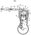
- FIG 1 we see a cylinder of a two-stroke engine generally designated by the reference 1 whose combustion chamber 2 is closed at its upper part by a cylinder head 3 and extended at its lower part by a pump casing 5 crossed by the crankshaft 6 of the engine.
- a piston 4 connected to the crankshaft 6 by means of a connecting rod 7 moves inside the cylinder, during the operation of the engine.
- the piston 4 delimits the combustion chamber 2, between its upper part and the inner wall of the cylinder head 3 and separates the combustion chamber 2 from the pump casing 5.
- the pump casing 5 has an air intake opening 8 through which atmospheric air is sucked in when the piston 4 moves in the cylinder, towards its top dead center, as represented by the arrow 10 in FIG. 1.
- a valve can be associated with the suction opening 8 and opens when the chamber of the pump casing 5 is in vacuum, the piston 4 moving in the direction of its neutral position. high, and closes when the air introduced into the pump housing 5 is compressed by the piston 4 moving towards its bottom dead center.
- the cylinder 1 has in its side wall transfer openings such as 12 communicating with the pump casing 5 and at least one exhaust opening 13 situated at a level slightly different from the level of the transfer openings 12 making it possible to evacuate the burnt gases of the combustion chamber 2.
- the piston 4 may have to mask or uncover the openings 12 and 13, depending on the phases of the cylinder's operating cycles.
- the pneumatic injection device 14 as shown in FIG. 1 can advantageously use certain elements of an injection device described in the published patent application FR-A-2 625 532.
- This device includes an injection capacity 16 communicating with the combustion chamber 2, via an injection orifice 17 constituting the seat of a valve 18 ensuring the opening and closing of the orifice. injection 17, during the engine operating cycle.
- the valve 18 is controlled for its opening, by a cam not shown and returned to its seat in the closed position by a spring.
- the control cam of the valve 18 is adjusted so as to ensure the opening of the orifice 17 and therefore the pneumatic injection of fuel into the cylinder, before the end of the compression phase in the combustion chamber 2, the piston 4 moving towards its top dead center.
- valve 18 closes at an instant adjusted so that a certain quantity of gas compressed in the combustion chamber 2 by the piston 4 at a determined pressure is returned to the capacity 16 to restore this capacity to pressure.
- This compressed gas will be used during the next opening of the valve 18 to carry out the transfer and the pneumatic spraying of the fuel delivered by the injector not shown.
- this injector could be placed in the vicinity of the valve 18.
- the piston 4 moves downwards and in particular ensures, as described above, the compression of the air introduced into the pump casing 5 and the sweeping of the combustion chamber 2 of the cylinder by fresh gases.
- Liquid fuel is introduced into the capacity 16, by means of an injector not shown and the pneumatic injection of fuel into the combustion chamber 2 can be ensured by opening the valve 18, during a phase of operation of the cylinder 1 during which the pressure in the combustion chamber 2 is lower than the pressure of the gases trapped in the capacity 16.
- the valve 18 opens, the pressurized gases contained in the capacity 16 flow at high speed in the chamber 2 through the injection orifice 17, driving the liquid fuel which is introduced into the chamber 2 in the sprayed state.
- the device as described does not make it possible to obtain a high ratio between the volume of compressed gases used for spraying the fuel and the volume of fuel injected, due to the design of the storage capacity 16 for compressed gases. and its supply mode during the cylinder operating cycle. This may result in insufficient spraying of the fuel, when the latter is injected in large quantities, when the engine is running at high load.
- the device described gives rise to certain constraints with regard to the timing of the camshaft controlling the valve for opening and closing the pneumatic injection orifice.
- the pneumatic injection device 14 of the cylinder 1 of the engine shown in FIG. 1 comprises a compressor 20 which can be driven mechanically by the engine or which can be constituted by a turbo-compressor driven in rotation by the exhaust gases from the engine .
- the compressor 20 comprises a suction pipe 21 on which is placed an adjusting butterfly 22 and a delivery pipe 23 connected at its opposite end to the compressor 20, to the capacity 16 and on which a heat exchanger 24 can be inserted and a valve 25.
- the valve 25 when the cylinder 1 operates at low load, the valve 25 is in its closed position and the pneumatic injection of fuel into the combustion chamber 2 is ensured only by the compressed gases introduced into the capacity 16.
- the compressor 20 driven in rotation, for example by the motor, provides a certain supply of compressed air to the capacity 16.
- the pneumatic injection of fuel is carried out, by opening the valve 18, spraying and injection tires are produced both by compressed gases introduced into capacity 16 and by pressurized air supplied by compressor 20.
- the flow rate of the compressor 20 can be adjusted by means of the butterfly 22, for example as a function of the load and of the engine speed.
- the quantity of compressed air introduced into the capacity 16 by the compressor 20 can be very largely preponderant, compared to the quantity of compressed gas introduced into the capacity 16, during the compression phase in the cylinder 1.
- this quantity is easily adjustable and it becomes possible to obtain a very good spraying of the fuel whatever the quantity of fuel to be injected. It is also possible to increase the engine speed and torque by operating a slight boost.
- the flow rate of the mixture of air and atomized fuel introduced into the combustion chamber being appreciably increased, the injection orifice and the valve can have substantially smaller dimensions, which makes it possible in particular to reduce the height of the cylinder head.
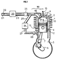
- the engine cylinder shown in Figure 2 is substantially identical to the cylinder shown in Figure 1.
- the pump casing 5 of the cylinder 1 shown in FIG. 2 has an additional opening connected, by via a valve 28 interposed on a line 27, with a compressed air capacity 26.
- the capacity 26 is itself connected via a line 29, to the line 23 of the pneumatic injection device 30 of the cylinder.
- the injection device 30 comprises in addition to the constituent elements similar to the elements of the injection device 14 shown in Figure 1, the capacity 26 and its connecting pipes to the pump housing 5 and capacity 16.
- Capacities 16 and 26 can be confused, for example, by directly connecting conduit 27 to capacitor 16 and by removing capacitor 26 and conduit 29 in FIG.
- Part of the air compressed by the piston 4 in the pump casing 5 is introduced into the capacity 16, by opening the valve 28, when the pressure of this compressed air is sufficient to open the valve 28.
- This compressed air is used to spray and drive the fuel injected into the tank 16, when the valve 18 opens.
- this device when the engine is running at high load, this device, when only the capacity 26 is used to supply the compressed injection air to the capacity 16, has substantially the same drawbacks as the device shown in FIG. 1.
- this device requires the presence of a compressed air capacity and a valve on a line connecting the compressed air capacity to the pump housing.
- the opening of the valve 25 and of the butterfly 22 placed on the suction line of the compressor 20 makes it possible to inject, via the discharge line 23, through the valve 25, an adjustable quantity of compressed air coming from the compressor 20.
- valve 18 When the valve 18 opens, the compressed air flow from the compressor 20 is added to the compressed air flow from the tank 26 to ensure a high air-to-fuel ratio and efficient spraying, at the time pneumatic injection.
- the air flow blown by the compressor 20 can be adjusted by the butterfly 22.
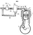
- FIG. 3 a cylinder of an engine is shown comprising a pneumatic fuel injection device 31 identical, in its general structure, to the injection device 14 shown in FIG. 1.
- the injection device 31 comprises a line 32 in bypass with respect to the compressor 20 joining the suction line 21 and the discharge line 23 of the compressor and on which can be placed the adjusting butterfly 22.
- a valve 33 is placed on the suction line 21 upstream of the bypass line 32.
- the operation of the cylinder 1 at low load is identical to the operation described with regard to the cylinder shown in FIG. 1.
- valve 25 opens and the additional compressed air flow introduced into the capacity 16 by the compressor 20 can be adjusted by means of the butterfly 22 placed on the line 32 in bypass with respect to the compressor 20.
- the devices as shown in FIGS. 1, 2 and 3 make it possible to adjust the flow rate of the additional compressed air supplied by the compressor 20.
- FIG. 4 shows an alternative embodiment of a two-stroke engine enabling the method according to the invention to be implemented using an injection device pneumatic 34 for adjusting the injection pressure of the additional air supplied by the compressor 20.
- the discharge line 23 of the compressor 20 is connected to a capacity 36 which is itself connected to the injection capacity 16, by means of a line 35 on which is placed an adjusting butterfly 37.
- a line 38 in bypass relative to the compressor 20 is connected to the capacity 36, by means of a valve 39.
- the throttle valve 37 When the engine is running at high load, the throttle valve 37 is open and the compressed air coming from the capacity 36 supplied by the compressor 20 contributes to the spraying and injection of the fuel into the chamber 2, when the valve 18.
- the pressure in the capacity 36 is limited to a maximum value defined by the setting value of the relief valve 39.
- FIGS. 3 and 4 can also be applied to the embodiment shown in FIG. 2.
- the injection device 40 includes a compressed air storage capacity 46 supplied by the compressor 20, via its discharge pipe 23 on which an exchanger 24 can be placed.
- the compressed air capacity 46 is connected to the injection capacity 16, via a pipe 45 on which is placed an adjusting butterfly 48.
- a line 44 is placed in bypass with respect to the compressor 20, so as to join the suction line 21 of the compressor on which a valve 43 can be placed to the capacity 46, by means of a discharge valve 49.
- the compressed air capacity 46 is connected to the transfer opening 12 of the cylinder 1, by means of a pipe such as 50 on which is placed an adjustment butterfly 51.
- the exhaust opening 13 of the cylinder can be placed in an arrangement opposite to the transfer openings, with respect to the axis of the cylinder 1.
- the flow rate of the fresh sweeping air from the chamber 2 of the cylinder can be adjusted using the butterfly valve 51.
- the pressure of the compressed air in the tank 46 is limited to a certain value defined by the setting value of the relief valve 49 or by a butterfly type butterfly 22 of FIG. 3.
- the injection of fuel into the chamber 2 can be carried out by opening the valve 18.
- the throttle valve 48 When the engine is running at low load, the throttle valve 48 is closed and the spraying and injection of fuel are carried out by the compressed gases stored in the capacity 16, at the time of the compression phase in the cylinder 1.
- the throttle valve 48 When the engine is running at high load, the throttle valve 48 is open and the fuel is sprayed and injected both by the compressed gases contained in capacity 16 and by the compressed air coming from capacity 46.
- the device shown in FIG. 5 makes it possible to use the compressor 20 and the capacity 46, both for supplying the cylinder with fresh air through its transfer openings 12 and for pneumatically injecting fuel, when opening of valve 18.
- the compressor 20 makes it possible to replace the pump casing 5 in its function of scanning the cylinder.
- the method according to the invention and the corresponding injection devices make it possible to increase the quantity of air injected to spray the fuel when the engine is running at high load.
- the method and the corresponding devices make it possible to achieve a supercharging of compressed air, by injecting additional air from a source external to the cylinder of the engine.
- This additional compressed air allows the use of smaller diameter valves; for the same lifting and opening characteristics of the valve, the production of a valve of smaller size and lower mass makes it possible to increase the operating speed of this valve and of the engine.
- the height of the cylinder head can be reduced and the timing of the camshaft controlling the opening of the injection valve can be facilitated.
- the source of compressed air outside the cylinder is generally constituted by a compressor, the drive of which can be ensured by a belt, starting from the crankshaft of the engine.
- FIG. 6 there is shown the cylinder 55 of a two-stroke engine having an exhaust opening 56 to which is connected an exhaust pipe 57.
- a turbo-compressor 60 is interposed on a pipe 59 placed in bypass on the exhaust pipe 57 of the engine.
- a throttle valve 58 makes it possible to adjust the flow rate of the exhaust gases in the main exhaust pipe 57.
- the turbo-compressor 60 the turbine of which is driven by the exhaust gases from the engine, can be substituted for the compressor 20 of the embodiments described and shown in FIGS. 1 to 5.
- FIG. 7 shows an alternative embodiment of the device comprising a turbo-compressor as shown in FIG. 6.
- the cylinder 55 ′ of the engine has a main exhaust opening 56 ′ to which a main exhaust pipe 57 ′ is connected.
- the cylinder 55 ′ has a second exhaust port 59′a to which is connected a secondary exhaust pipe 59 ′ on which the turbo-compressor 60 ′ is inserted.
- the secondary exhaust pipe 59 ′ is connected to the main pipe 57 ′ downstream from the turbo-compressor 60 ′.
- the exhaust ports 56 ′ and 59′a in the case of the embodiment shown in FIG. 7, can be arranged at the same level in the axial direction of the cylinder or at slightly different levels; in the latter case, these lights have offset opening angles.
- the light connected to the pipe supplying the turbine of the turbo-compressor may open first and therefore supply the turbine with gases at a relatively high pressure.
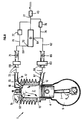
- FIG. 8 is particularly well suited for best controlling the pressures and the air flow rates used for fuel injection and for sweeping the cylinder.
- the performance of the engine is in fact improved when there is a large air flow to effectively sweep the burnt gases out of the combustion chamber and a high gas injection pressure in the injection capacity for obtain a fuel mixture at high pressure.
- This embodiment of the engine according to the invention comprises for this purpose a compression assembly 61 which can deliver air at at least two different pressures and with different flow rates.
- This assembly can consist for example of a compressor with at least two stages driven in rotation by the engine or which can be constituted by a turbo-compressor driven in rotation by the exhaust gases of the engine.
- the compressor 61 is connected to a suction pipe 21 on which a valve 43 is placed.
- a first discharge line 62 communicates with a first capacity 63 an intermediate outlet 64 of the compressor 61 delivering compressed air at a first pressure .
- a heat exchanger 65 can be placed on the line 62 to cool the air from the compressor.
- Another pipe 66 on which is possibly placed a control butterfly 67 connects the first capacity 63 with the inlet 12 serving for the injection of air into the combustion chamber 2 for sweeping the burnt gases.
- a second discharge line 68 communicates with a second capacity 69, another outlet 70 of the compressor 61 delivering air at a second pressure greater than the first pressure with a lower flow rate.
- Another heat exchanger 71 can also be placed on the pipe 68 to cool the air coming from the compressor.
- a pipe 72 possibly provided with a control butterfly 73, connects the second capacity 69 to the injection capacity 16 where the mixing with the fuel takes place.
- a non-return valve is preferably placed in the pipe 72 to prevent any circulation from the capacity 16 towards the outlet 70 of the compressor 61.
- the suction pipe 21 of the compressor can be connected by pipes 74, 75 respectively with pipes 62 and 68.
- Two discharge control means such as valves 76, 77 calibrated at two different threshold pressures or butterflies, are arranged respectively on the pipes 74, 75.
- These branches for the pipes 74, 75 are useful for better control of the pressures in the capacities 63, 69 but they can possibly be eliminated.
- the compression assembly may include, for example, a screw compressor with one or more intermediate outputs. It can also optionally include two compressors interconnected in series.
- the butterflies 67 and 73 on the two pipes 66, 72 allow an additional adjustment of the air flow rates and pressures as a function of the load.
- compression means of any type capable of delivering gas under pressure at one or more different pressures such as for example an exhaust wave system of the Comprex type. .
- pneumatic injection control means comprising a valve controlled mechanically by a cam. It is quite obvious that one can use in this function a valve controlled by an electromagnetic device or in the form of a rotary plug carrying out the opening or the closing of the injection orifice and driven in rotation by the crankshaft of the engine .
- the invention applies to any two-stroke engine with pneumatic injection.
Description
L'invention concerne un procédé d'injection pneumatique de carburant dans un moteur à deux temps à un ou plusieurs cylindres.The invention relates to a pneumatic fuel injection method in a two-stroke engine with one or more cylinders.
Dans les moteurs à deux temps à un ou plusieurs cylindres, à haut rendement on cherche à réaliser de façon indépendante, un balayage du ou des cylindres par de l'air frais non carburé et une introduction de carburant liquide sous forme pulvérisée dans le ou les cylindres, ces deux opérations étant effectuées à des instants successifs et bien déterminés du cycle de fonctionnement du moteur.In two-stroke engines with one or more cylinders, with high efficiency, it is sought to carry out independently, a sweeping of the cylinder (s) with fresh non-carburetted air and an introduction of liquid fuel in spray form into the cylinders, these two operations being carried out at successive and well-defined instants of the engine operating cycle.
L'introduction de carburant sous forme pulvérisée dans le cylindre peut être réalisée par un dispositif d'injection pneumatique comportant un injecteur débouchant dans le cylindre muni d'une soupape commandée par une came pour son ouverture et sa fermeture, un moyen d'alimentation de l'injecteur en carburant liquide et une source d'air comprimé assurant la pulvérisation et l'injection du carburant au moment de l'ouverture de l'injecteur.The introduction of fuel in spray form into the cylinder can be carried out by a pneumatic injection device comprising an injector opening into the cylinder provided with a valve controlled by a cam for its opening and closing, a supply means for the liquid fuel injector and a source of compressed air ensuring the atomization and injection of the fuel when the injector is opened.
Le balayage du cylindre par de l'air frais peut être par exemple réalisé au moyen d'un carter pompe communiquant avec le cylindre à sa partie inférieure, de façon que le piston se déplaçant dans le cylindre produise une compression de l'air du carter en se déplaçant vers son point mort bas. Des conduits joignant le carter pompe à des lumières d'admission du cylindre assurent le transfert de l'air comprimé vers le cylindre, cet air comprimé pénétrant dans le cylindre dont il réalise le balayage, lorsque les lumières d'admission sont découvertes par le piston au cours de son déplacement vers son point mort bas.The sweeping of the cylinder with fresh air can for example be carried out by means of a pump casing communicating with the cylinder at its lower part, so that the piston moving in the cylinder produces a compression of the air of the casing moving towards its bottom dead center. Ducts joining the pump casing to the cylinder intake ports ensure the transfer of compressed air to the cylinder, this compressed air entering the cylinder which it scans when the intake lights are discovered by the piston during its movement towards its bottom dead center.
L'injection pneumatique du carburant est réalisée par exemple en utilisant l'air comprimé dans un carter pompe pour effectuer la pulvérisation et l'injection du carburant. A cette fin, le carter pompe peut être relié à l'injecteur par un conduit sur lequel est disposé un clapet. La partie du conduit située en aval du clapet peut constituer en elle-même une capacité. Lors de l'ouverture de l'injecteur, une certaine quantité d'air comprimé est utilisée pour pulvériser le carburant et l'injecter dans le cylindre. Le rechargement de la capacité en air comprimé est réalisé, lorsque la pression est voisine de son maximum dans le carter pompe, par ouverture du clapet.The pneumatic fuel injection is carried out for example by using the compressed air in a pump housing to carry out the spraying and the injection of the fuel. To this end, the pump housing can be connected to the injector by a duct on which a valve is arranged. The part of the conduit located downstream of the valve can in itself constitute a capacity. When the injector is opened, a certain amount of compressed air is used to spray the fuel and inject it into the cylinder. The recharging of the compressed air capacity is carried out, when the pressure is close to its maximum in the pump housing, by opening the valve.
Par la demande de brevet FR-A-2 625 532 (EP-A-0 323 368) on connait un procédé d'injection où la pulvérisation et l'injection du carburant dans un cylindre d'un moteur à deux temps sont réalisées en utilisant des gaz prélevés dans le cylindre du moteur ou, dans le cas d'un moteur à plusieurs cylindres, dans un cylindre du moteur différent du cylindre dans lequel on réalise l'injection.By patent application FR-A-2 625 532 (EP-A-0 323 368) there is known an injection process where the spraying and injection of fuel into a cylinder of a two-stroke engine are carried out in using gases taken from the engine cylinder or, in the case of a multi-cylinder engine, from an engine cylinder different from the cylinder in which the injection is carried out.
L'injecteur pneumatique de carburant peut être alimenté en gaz sous pression, dans un mode de réalisation particulier, par une capacité de stockage reliée à la chambre du cylindre dans lequel a lieu l'injection, par l'intermédiaire de la chambre de l'injecteur pneumatique débouchant dans la partie supérieure du cylindre au niveau d'un siège d'une soupape de fermeture et d'ouverture.The pneumatic fuel injector can be supplied with pressurized gas, in a particular embodiment, by a storage capacity connected to the chamber of the cylinder in which the injection takes place, via the chamber of the pneumatic injector opening into the upper part of the cylinder at a seat of a closing and opening valve.
On obtient ainsi des performances accrues. Cependant on constate que les moteurs à deux temps fonctionnant suivant les procédés d'injection connus dans la technique antérieure ne permettent pas toujours d'obtenir des performances suffisantes, notamment lorsqu'ils fonctionnent à fortes charges.This gives increased performance. However, it can be seen that two-stroke engines operating according to the injection methods known in the prior art do not always make it possible to obtain sufficient performance, in particular when they operate at high loads.
Le rapport air/carburant au moment de l'injection est souvant insuffisant pour obtenir une bonne pulvérisation du carburant et une combustion efficace. Il n'est généralement pas possible de suralimenter le moteur pour obtenir une augmentation du couple.The air / fuel ratio at the time of injection is often insufficient to obtain good fuel atomization and efficient combustion. It is generally not possible to overfeed the engine to obtain an increase in torque.
Les conditions de mise en oeuvre de la distribution conduisent également à des limitations quant au régime de fonctionnement du moteur.The conditions of implementation of the distribution also lead to limitations as to the engine operating regime.
Les soupapes d'admission du mélange carburé doivent présenter une dimension relativement importante, ce qui conduit à utiliser une culasse d'une hauteur également importante.The fuel mixture intake valves must have a relatively large dimension, which leads to the use of a cylinder head of an equally large height.
Le procédé d'injection selon la présente invention permet d'éviter les inconvénients ci-dessus mentionnés. Il s'applique à un moteur à deux temps comportant au moins un cylindre dans lequel se déplace un piston délimitant une chambre de combustion et un carter situé dans le prolongement de la chambre de combustion et séparé de celle-ci par le piston, au moins une ouverture d'admission d'air frais dans la chambre de combustion communiquant avec un élément délivrant de l'air frais, au moins une ouverture d'échappement de gaz brûlés de la chambre de combustion ainsi qu'un dispositif d'injection pneumatique de carburant dans la chambre de combustion par un orifice d'injection. Ce dispositif d'injection comporte un moyen d'ouverture et de fermeture de l'orifice d'injection, une capacité d'injection alimentée en gaz comprimé communiquant avec la chambre de combustion par l'intermédiaire de l'orifice d'injection et un moyen d'injection de carburant liquide dans la capacité d'injection. Dans le but d'accroître les performances du moteur et de diminuer les dimensions de certaines de ces pièces, on utilise pour réaliser l'injection, un gaz comprimé provenant uniquement de la chambre ou du carter délivrant de l'air frais à un cylindre du moteur pour les faibles charges du moteur et de manière additionnelle, un gaz comprimé provenant d'une source extérieure au cylindre pour les fortes charges du moteur, telle qu'un compresseur ou un turbo-compresseur par exemple, qui peut être à plusieurs étages de façon à remplir au mieux une double fonction : délivrer de l'air pour constituer le mélange carburé qui est injecté dans la chambre de combustion d'un support, et pour balayer les gaz brûlés d'autre part.The injection method according to the present invention makes it possible to avoid the above-mentioned drawbacks. It applies to a two-stroke engine comprising at least one cylinder in which moves a piston delimiting a combustion chamber and a casing situated in the extension of the combustion chamber and separated from the latter by the piston, at least an opening for the admission of fresh air into the combustion chamber communicating with an element delivering fresh air, at least one opening for exhausting burnt gases from the combustion chamber as well as a pneumatic injection device for fuel into the combustion chamber through an injection port. This injection device comprises a means for opening and closing the injection orifice, an injection capacity supplied with compressed gas communicating with the combustion chamber via the injection orifice and a means for injecting liquid fuel into the injection capacity. In order to increase the performance of the engine and to reduce the dimensions of some of these parts, use is made to carry out the injection, a compressed gas coming only from the chamber or from the casing delivering fresh air to a cylinder of the engine for low engine loads and additionally, a compressed gas from a source external to the cylinder for heavy engine loads, such as a compressor or a turbo-compressor for example, which can be in several stages of so as to best fulfill a double function: deliver air to constitute the fuel mixture which is injected into the combustion chamber of a support, and to sweep the burnt gases on the other hand.
Dans tous les cas, les moteurs à deux temps mettant en oeuvre le procédé suivant l'invention permettent d'obtenir à la fois un démarrage aisé, dans la mesure où il n'est pas nécessaire d'utiliser de l'air comprimé extérieur aux faibles charges et un très bon fonctionnement à forte ou à pleine charge, grâce à des quantités additionnelles d'air comprimé provenant d'une source extérieure au cylindre du moteur.In all cases, the two-stroke engines implementing the method according to the invention make it possible to obtain both an easy start, insofar as it is not necessary to use compressed air outside the low loads and very good operation at high or full load, thanks to additional amounts of compressed air from a source external to the engine cylinder.
D'autres caractéristiques importantes du procédé d'injection selon l'invention et du moteur qui le met en oeuvre apparaîtront mieux à la lecture de la description qui suit de plusieurs modes de réalisation décrits à titre d'exemples non limitatifs et en se référant aux dessins annexés où :
- les figures 1, 2, 3, 4 et 5 sont des vues en élévation et en coupe par un plan vertical d'un cylindre d'un moteur à deux temps permettant de mettre en oeuvre le procédé suivant l'invention, et suivant cinq modes de réalisation différents;
- les figures 6 et 7 sont des vues schématiques en coupe par un plan horizontal montrant la disposition d'un turbo-compresseur utilisé comme source de gaz comprimé, dans la mise en oeuvre du procédé suivant l'invention; et
- la figure 8 montre une variante du mode de mise en oeuvre précédent avec un moyen de compression à plusieurs étages.
- Figures 1, 2, 3, 4 and 5 are views in elevation and in section through a vertical plane of a cylinder of a two-stroke engine for implementing the method according to the invention, and according to five modes of different achievements;
- Figures 6 and 7 are schematic sectional views on a horizontal plane showing the arrangement of a turbo-compressor used as a source of compressed gas, in the implementation of the method according to the invention; and
- FIG. 8 shows a variant of the previous embodiment with a multi-stage compression means.
On va maintenant décrire en se référant aux figures 1 à 5, plusieurs modes de réalisation d'un moteur à deux temps permettant la mise en oeuvre du procédé d'injection pneumatique suivant l'invention. Les éléments correspondants sur les figures 1 à 5 portent les mêmes repères.We will now describe with reference to Figures 1 to 5, several embodiments of a two-stroke engine allowing the implementation of the pneumatic injection method according to the invention. The corresponding elements in Figures 1 to 5 bear the same references.
Sur la figure 1, on voit un cylindre d'un moteur à deux temps désigné de manière générale par le repère 1 dont la chambre de combustion 2 est fermée à sa partie supérieure par une culasse 3 et prolongée à sa partie inférieure par un carter pompe 5 traversé par le vilebrequin 6 du moteur.In Figure 1, we see a cylinder of a two-stroke engine generally designated by the
Un piston 4 relié au vilebrequin 6 par l'intermédiaire d'une bielle 7 se déplace à l'intérieur du cylindre, pendant le fonctionnement du moteur.A
Le piston 4 délimite la chambre de combustion 2, entre sa partie supérieure et la paroi intérieure de la culasse 3 et sépare la chambre de combustion 2 du carter pompe 5.The
Le carter pompe 5 comporte une ouverture d'admission d'air 8 par laquelle de l'air atmosphérique est aspiré lorsque le piston 4 se déplace dans le cylindre, en direction de son point mort haut, comme représenté par la flèche 10 sur la figure 1. Un clapet peut être associé à l'ouverture d'aspiration 8 et s'ouvre lorsque la chambre du carter pompe 5 est en dépression, le piston 4 se déplaçant en direction de son point mort haut, et se referme, lorsque l'air introduit dans le carter pompe 5 est comprimé par le piston 4 se déplaçant en direction de son point mort bas.The
Le cylindre 1 comporte dans sa paroi latérale des ouvertures de transfert telles que 12 communiquant avec le carter pompe 5 et au moins une ouverture d'échappement 13 située à un niveau légèrement différent du niveau des ouvertures de transfert 12 permettant d'évacuer les gaz brûlés de la chambre de combustion 2. Lors de ses déplacements dans le cylindre, le piston 4 peut être amené à masquer ou à découvrir les ouvertures 12 et 13, suivant les phases du cycles de fonctionnement du cylindre.The
Lorsque le piston 4 qui se déplace en direction de son point mors bas comprime l'air introduit dans le carter pompe 5, cet air comprimé est introduit par les ouvertures de transfert 12 dans la chambre de combustion 2, les gaz brûlés étant évacués par l'ouverture 13. Du carburant pulvérisé est introduit dans la chambre de combustion 2 par le dispositif d'injection pneumatique 14, mélangé à l'air frais comburant introduit dans la chambre de combustion 2 et enflammé par la bougie 15.When the
Le dispositif d'injection pneumatique 14 tel que représenté sur la figure 1 peut utiliser avantageusement certains éléments d'un dispositif d'injection décrit dans la demande de brevet publiée FR-A-2 625 532.The
Ce dispositif comporte une capacité d'injection 16 communiquant avec la chambre de combustion 2, par l'intermédiaire d'un orifice d'injection 17 constituant le siège d'une soupape 18 assurant l'ouverture et la fermeture de l'orifice d'injection 17, pendant le cycle de fonctionnement du moteur.This device includes an
La soupape 18 est commandée pour son ouverture, par une came non représentée et rappelée sur son siège en position de fermeture par un ressort.The
La came de commande de la soupape 18 est réglée de manière à assurer l'ouverture de l'orifice 17 et donc l'injection pneumatique de carburant dans le cylindre, avant la fin de la phase de compression dans la chambre de combustion 2, le piston 4 se déplaçant en direction de son point mort haut.The control cam of the
La soupape 18 se referme à un instant réglé de manière qu'une certaine quantité de gaz comprimé dans la chambre de combustion 2 par le piston 4 à une pression déterminée est renvoyée dans la capacité 16 pour remettre cette capacité en pression. Ce gaz comprimé servira lors de l'ouverture suivante de la soupape 18 à réaliser le transfert et la pulvérisation pneumatique du carburant délivré par l'injecteur non représenté. Avantageusement, cet injecteur pourra être placé au voisinage de la soupape 18.The
Après l'inflammation du mélange carburé et comprimé, par la bougie 15, le piston 4 se déplace vers le bas et assure en particulier, comme décrit plus haut, la compression de l'air introduit dans le carter pompe 5 et le balayage de la chambre de combustion 2 du cylindre par des gaz frais.After ignition of the fuel and compressed mixture, by the
Du carburant liquide est introduit dans la capacité 16, grâce à un injecteur non représenté et l'injection pneumatique de carburant dans la chambre de combustion 2 peut être assurée par ouverture de la soupape 18, pendant une phase du fonctionnement du cylindre 1 pendant laquelle la pression dans la chambre de combustion 2 est inférieure à la pression des gaz emprisonnés dans la capacité 16. Au moment de l'ouverture de la soupape 18, les gaz sous pression contenus dans la capacité 16 s'écoulent à grande vitesse dans la chambre 2 par l'orifice d'injection 17, en entraînant le carburant liquide qui est introduit dans la chambre 2 à l'état pulvérisé.Liquid fuel is introduced into the
Ce type de fonctionnement est parfaitement satisfaisant, lorsque le moteur est à faible charge et à régime modéré.This type of operation is perfectly satisfactory, when the engine is at low load and at moderate speed.
Cependant, le dispositif tel que décrit ne permet pas d'obtenir un rapport élevé entre le volume des gaz comprimés servant à la pulvérisation du carburant et le volume de carburant injecté, du fait de la conception de la capacité 16 de stockage des gaz comprimés et de son mode d'alimentation au cours du cycle de fonctionnement du cylindre. Il peut en résulter une pulvérisation insuffisante du carburant, lorsque celui-ci est injecté en quantités importantes, lors du fonctionnement du moteur à forte charge.However, the device as described does not make it possible to obtain a high ratio between the volume of compressed gases used for spraying the fuel and the volume of fuel injected, due to the design of the
En outre, il n'est pas possible d'augmenter le couple moteur en effectuant une légère suralimentation.In addition, it is not possible to increase the engine torque by performing a slight boost.
Il est également très difficile de faire fonctionner le moteur à haut régime, du fait des conditions de fonctionnement du dispositif d'injection de carburant.It is also very difficult to operate the engine at high speed, due to the operating conditions of the fuel injection device.
Il est nécessaire de prévoir un orifice d'injection et une soupape d'une dimension suffisante pour assurer une alimentation satisfaisante de la chambre de combustion. Il en résulte une dimension accrue de la culasse et une inertie plus importante de la soupape.It is necessary to provide an injection orifice and a valve of sufficient size to ensure satisfactory supply of the combustion chamber. This results in an increased size of the cylinder head and greater inertia of the valve.
En outre, le dispositif décrit entraîne certaines contraintes en ce qui concerne le calage de l'arbre à cames commandant la soupape d'ouverture et de fermeture de l'orifice d'injection pneumatique.In addition, the device described gives rise to certain constraints with regard to the timing of the camshaft controlling the valve for opening and closing the pneumatic injection orifice.
Le dispositif d'injection pneumatique 14 du cylindre 1 du moteur représenté sur la figure 1 comporte un compresseur 20 qui peut être entraîné mécaniquement par le moteur ou qui peut être constitué par un turbo-compresseur entraîné en rotation par les gaz d'échappement du moteur.The
Le compresseur 20 comporte une tubulure d'aspiration 21 sur laquelle est placé un papillon de réglage 22 et une tubulure de refoulement 23 reliée à son extrémité opposée au compresseur 20, à la capacité 16 et sur laquelle peut être intercalé un échangeur de chaleur 24 et un clapet 25.The
Selon l'invention, lorsque le cylindre 1 fonctionne à faible charge, le clapet 25 est dans sa position de fermeture et l'injection pneumatique du carburant dans la chambre de combustion 2 est assurée uniquement par les gaz comprimés introduits dans la capacité 16.According to the invention, when the
Lorsque la charge et la puissance demandée au moteur dépassent une certaine limite, par ouverture du clapet 25, le compresseur 20 entraîné en rotation, par exemple par le moteur assure une certaine alimentation en air comprimé de la capacité 16. Au moment où l'on réalise l'injection pneumatique du carburant, par ouverture de la soupape 18, la pulvérisation et l'injection pneumatique sont réalisées à la fois par les gaz comprimés introduits dans la capacité 16 et par l'air sous pression fourni par le compresseur 20.When the load and the power demanded of the motor exceed a certain limit, by opening the
Le débit du compresseur 20 peut être réglé grâce au papillon 22, par exemple en fonction de la charge et du régime du moteur.The flow rate of the
La quantité d'air comprimé introduite dans la capacité 16 par le compresseur 20 peut être très largement prépondérante, par rapport à la quantité de gaz comprimé introduit dans la capacité 16, pendant la phase de compression dans le cylindre 1.The quantity of compressed air introduced into the
En outre, cette quantité est facilement réglable et il devient possible d'obtenir une très bonne pulvérisation du carburant quelle que soit la quantité de carburant à injecter. Il est également possible d'augmenter le régime du moteur et le couple en opérant une légère suralimentation.In addition, this quantity is easily adjustable and it becomes possible to obtain a very good spraying of the fuel whatever the quantity of fuel to be injected. It is also possible to increase the engine speed and torque by operating a slight boost.
Le débit du mélange d'air et de carburant pulvérisé introduit dans la chambre de combustion étant sensiblement accru, l'orifice d'injection et la soupape peuvent avoir des dimensions sensiblement inférieures, ce qui permet de diminuer en particulier la hauteur de la culasse.The flow rate of the mixture of air and atomized fuel introduced into the combustion chamber being appreciably increased, the injection orifice and the valve can have substantially smaller dimensions, which makes it possible in particular to reduce the height of the cylinder head.
Il est également possible d'effectuer un calage plus tardif de l'arbre à cames, dans la mesure où on dispose d'un niveau de pression accru dans la capacité 16 obtenue grâce à une quantité additionnelle d'air comprimé fourni par une source totalement extérieure au cylindre dans lequel on réalise l'injection.It is also possible to perform a later setting of the camshaft, as long as there is an increased pressure level in the
Sur la figure 2, on a représenté une variante de réalisation d'un moteur à deux temps permettant de mettre en oeuvre le procédé suivant l'invention.In Figure 2, there is shown an alternative embodiment of a two-stroke engine for implementing the method according to the invention.
Le cylindre du moteur représenté sur la figure 2 est sensiblement identique au cylindre représenté sur la figure 1.The engine cylinder shown in Figure 2 is substantially identical to the cylinder shown in Figure 1.
Cependant, le carter pompe 5 du cylindre 1 représenté sur la figure 2 comporte une ouverture supplémentaire reliée, par l'intermédiaire d'un clapet 28 intercalé sur une conduite 27, à une capacité d'air comprimé 26. La capacité 26 est elle-même reliée par l'intermédiaire d'une conduite 29, au conduit 23 du dispositif d'injection pneumatique 30 du cylindre.However, the
Dans le cas de la variante représentée sur la figure 2, le dispositif d'injection 30 comporte en plus des éléments constitutifs analogues aux éléments du dispositif d'injection 14 représenté sur la figure 1, la capacité 26 et ses conduits de liaison au carter pompe 5 et à la capacité 16.In the case of the variant shown in Figure 2, the
Les capacités 16 et 26 pourront être confondues, par exemple, en reliant directement le conduit 27 à la capacité 16 et en supprimant la capacité 26 et la conduite 29 de la figure 2.
Une partie de l'air comprimé par le piston 4 dans le carter pompe 5 est introduit dans la capacité 16, par ouverture du clapet 28, lorsque la pression de cet air comprimé est suffisante pour réaliser l'ouverture du clapet 28.Part of the air compressed by the
Au moment de l'ouverture des transferts 12, la pression dans le carter pompe 5 diminue et le clapet 20 se referme, de manière que de l'air comprimé se trouve emprisonné dans la capacité 26.When the
Cet air comprimé est utilisé pour réaliser la pulvérisation et l'entraînement du carburant injecté dans la capacité 16, au moment de l'ouverture de la soupape 18.This compressed air is used to spray and drive the fuel injected into the
Lorsque le moteur fonctionne à faible charge et à régime modéré, ce dispositif d'injection pneumatique de type classique fonctionne de manière satisfaisante.When the engine is operating at low load and at moderate speed, this conventional type pneumatic injection device operates satisfactorily.
Lorsque le moteur fonctionne à forte charge, ce dispositif, lorsqu'on ne met en oeuvre que la capacité 26 pour fournir l'air comprimé d'injection à la capacité 16, présente sensiblement les mêmes inconvénients que le dispositif représenté sur la figure 1.When the engine is running at high load, this device, when only the
De plus, ce dispositif nécessite la présente d'une capacité d'air comprimé et d'un clapet sur une conduite de liaison de la capacité d'air comprimé au carter pompe.In addition, this device requires the presence of a compressed air capacity and a valve on a line connecting the compressed air capacity to the pump housing.
Selon l'invention, lorsque le moteur fonctionne à forte charge, l'ouverture du clapet 25 et du papillon 22 placé sur la conduite d'aspiration du compresseur 20 permet d'injecter par la conduite de refoulement 23, à travers le clapet 25, une quantité réglable d'air comprimé provenant du compresseur 20.According to the invention, when the engine is running at high load, the opening of the
Au moment de l'ouverture de la soupape 18, le débit d'air comprimé provenant du compresseur 20 s'ajoute au débit d'air comprimé provenant de la capacité 26 pour assurer un rapport élevé air sur carburant et une pulvérisation efficace, au moment de l'injection pneumatique.When the
Comme précédemment, le débit d'air insufflé par le compresseur 20 peut être réglé par le papillon 22.As before, the air flow blown by the
Sur la figure 3, on a représenté un cylindre d'un moteur comportant un dispositif d'injection pneumatique de carburant 31 identique, dans sa structure générale, au dispositif d'injection 14 représenté sur la figure 1.In FIG. 3, a cylinder of an engine is shown comprising a pneumatic
Cependant, à la différence du dispositif représenté sur la figure 1, le dispositif d'injection 31 comporte une conduite 32 en dérivation par rapport au compresseur 20 joignant la conduite d'aspiration 21 et la conduite de refoulement 23 du compresseur et sur laquelle peut être placé le papillon de réglage 22. Un clapet 33 est placé sur la conduite d'aspiration 21 en amont de la conduite 32 en dérivation.However, unlike the device shown in FIG. 1, the
Le fonctionnement du cylindre 1 à faible charge est identique au fonctionnement décrit en ce qui concerne le cylindre représenté sur la figure 1.The operation of the
A forte charge, le clapet 25 s'ouvre et le débit d'air comprimé additionnel introduit dans la capacité 16 par le compresseur 20 peut être réglé grâce au papillon 22 placé sur la conduite 32 en dérivation par rapport au compresseur 20.At high load, the
Les dispositifs tels que représentés sur les figures 1, 2 et 3 permettent de régler le débit de l'air comprimé additionnel fourni par le compresseur 20.The devices as shown in FIGS. 1, 2 and 3 make it possible to adjust the flow rate of the additional compressed air supplied by the
Sur la figure 4, on a représenté une variante de réalisation d'un moteur à deux temps permettant de mettre en oeuvre le procédé suivant l'invention grâce à un dispositif d'injection pneumatique 34 permettant de régler la pression d'injection de l'air additionnel fourni par le compresseur 20.FIG. 4 shows an alternative embodiment of a two-stroke engine enabling the method according to the invention to be implemented using an
La conduite de refoulement 23 du compresseur 20 est reliée à une capacité 36 elle-même reliée à la capacité d'injection 16, par l'intermédiaire d'une conduite 35 sur laquelle est placé un papillon de réglage 37. Une conduite 38 en dérivation par rapport au compresseur 20 est reliée à la capacité 36, par l'intermédiaire d'un clapet 39.The
Lorsque le moteur fonctionne à forte charge, le papillon 37 est ouvert et l'air comprimé provenant de la capacité 36 alimentée par le compresseur 20 contribue à la pulvérisation et à l'injection du carburant dans la chambre 2, lors de l'ouverture de la soupape 18.When the engine is running at high load, the
La pression dans la capacité 36 est limitée à une valeur maximale définie par la valeur de tarage du clapet de décharge 39.The pressure in the
Les variantes illustrées aux figures 3 et 4 pourront également être appliquées au mode de réalisation représenté à la figure 2.The variants illustrated in FIGS. 3 and 4 can also be applied to the embodiment shown in FIG. 2.
Sur la figure 5, on a représenté une variante de réalisation d'un moteur à deux temps comportant un dispositif d'injection 40 permettant de mettre en oeuvre le procédé suivant l'invention.In Figure 5, there is shown an alternative embodiment of a two-stroke engine comprising an
Le dispositif d'injection 40 comporte une capacité de stockage d'air comprimé 46 alimentée par le compresseur 20, par l'intermédiaire de sa conduite de refoulement 23 sur laquelle peut être disposé un échangeur 24. La capacité d'air comprimé 46 est reliée à la capacité d'injection 16, par l'intermédiaire d'une conduite 45 sur laquelle est placé un papillon de réglage 48.The
Une conduite 44 est placée en dérivation par rapport au compresseur 20, de manière à joindre la conduite d'aspiration 21 du compresseur sur laquelle peut être placé un clapet 43 à la capacité 46, par l'intermédiaire d'un clapet de décharge 49.A
De plus, la capacité d'air comprimé 46 est reliée à l'ouverture de transfert 12 du cylindre 1, par l'intermédiaire d'une conduite telle que 50 sur laquelle est placé un papillon de réglage 51.In addition, the
L'ouverture d'échappement 13 du cylindre pourra être placée dans une disposition opposée aux ouvertures de transfert, par rapport à l'axe du cylindre 1.The
De cette manière, lorsque le piston 4 est parvenu au voisinage de son point mort bas, comme représenté sur la figure 5, la ou les ouvertures de transfert 12 sont dégagées par le piston 4, de manière que l'air comprimé contenu dans la capacité 46 et provenant du compresseur 20 permet de réaliser le balayage de la chambre 2 et son remplissage en air frais (flèches 53).In this way, when the
Le débit de l'air frais de balayage de la chambre 2 du cylindre peut être réglé grâce au papillon 51.The flow rate of the fresh sweeping air from the
En outre, la pression de l'air comprimé dans la capacité 46 est limitée à une certaine valeur définie par la valeur de tarage du clapet de décharge 49 ou par un papillon de réglage du type du papillon 22 de la figure 3.In addition, the pressure of the compressed air in the
Lorsque le balayage et le remplissage en air frais de la chambre de combustion 2 ont été réalisés, l'injection de carburant dans la chambre 2 peut être effectuée par ouverture de la soupape 18.When the
Lorsque le moteur fonctionne à faible charge, le papillon 48 est fermé et la pulvérisation et l'injection de carburant sont effectuées par les gaz comprimés stockés dans la capacité 16, au moment de la phase de compression dans le cylindre 1.When the engine is running at low load, the
Lorsque le moteur fonctionne à forte charge, le papillon 48 est ouvert et la pulvérisation et l'injection du carburant sont assurées à la fois par les gaz comprimés contenus dans la capacité 16 et par l'air comprimé provenant de la capacité 46.When the engine is running at high load, the
La pression de cet air comprimé est limitée à une certaine valeur maximale grâce au clapet de décharge 49.The pressure of this compressed air is limited to a certain maximum value by virtue of the
Le dispositif représenté sur la figure 5 permet d'utiliser le compresseur 20 et la capacité 46, aussi bien pour l'alimentation du cylindre en air frais par ses ouvertures de transfert 12 que pour l'injection pneumatique du carburant, lors de l'ouverture de la soupape 18.The device shown in FIG. 5 makes it possible to use the
Dans ce cas, le compresseur 20 permet de remplacer le carter pompe 5 dans sa fonction de balayage du cylindre.In this case, the
Dans tous les cas, le procédé suivant l'invention et les dispositifs d'injection correspondants permettent d'augmenter la quantité d'air injecté pour réaliser la pulvérisation du carburant, lorsque le moteur fonctionne à forte charge.In all cases, the method according to the invention and the corresponding injection devices make it possible to increase the quantity of air injected to spray the fuel when the engine is running at high load.
Le procédé et les dispositifs correspondants permettent de réaliser une suralimentation en air comprimé, grâce à l'injection d'air additionnel provenant d'une source extérieure au cylindre du moteur. Ce complément d'air comprimé permet d'utiliser des soupapes de plus petit diamètre; pour les mêmes caractéristiques de levée et d'ouverture de la soupape, la réalisation d'une soupape de plus faible dimension et de plus faible masse permet d'accroître le régime de fonctionnement de cette soupape et du moteur.The method and the corresponding devices make it possible to achieve a supercharging of compressed air, by injecting additional air from a source external to the cylinder of the engine. This additional compressed air allows the use of smaller diameter valves; for the same lifting and opening characteristics of the valve, the production of a valve of smaller size and lower mass makes it possible to increase the operating speed of this valve and of the engine.
En outre, la hauteur de la culasse peut être diminuée et le calage de l'arbre à cames commandant l'ouverture de la soupape d'injection peut être facilité.In addition, the height of the cylinder head can be reduced and the timing of the camshaft controlling the opening of the injection valve can be facilitated.
La source d'air comprimé extérieure au cylindre est généralement constituée par un compresseur dont l'entraînement peut être assuré par une courroie, à partir du vilebrequin du moteur.The source of compressed air outside the cylinder is generally constituted by a compressor, the drive of which can be ensured by a belt, starting from the crankshaft of the engine.
Il est également possible d'utiliser un turbo-compresseur dont la turbine est mise en rotation par les gaz d'échappement du moteur.It is also possible to use a turbo-compressor whose turbine is rotated by the engine exhaust gases.
Sur la figure 6, on a représenté le cylindre 55 d'un moteur à deux temps comportant une ouverture d'échappement 56 à laquelle est reliée une conduite d'échappement 57. Un turbo-compresseur 60 est intercalé sur une conduite 59 placée en dérivation sur la conduite d'échappement 57 du moteur. Un papillon 58 permet de régler le débit des gaz d'échappement dans le conduite d'échappement principale 57.In Figure 6, there is shown the
En fonction de la position de réglage du papillon 58, une certaine fraction des gaz d'échappement circule dans la conduite 59 et assure la mise en rotation du turbo-compresseur 60.Depending on the
Le turbo-compresseur 60 dont la turbine est entraînée par les gaz d'échappement du moteur peut être substitué au compresseur 20 des modes de réalisation décrits et représentés sur les figures 1 à 5.The turbo-
Sur la figure 7, on a représenté une variante de réalisation du dispositif comportant un turbo-compresseur tel que représenté sur la figure 6.FIG. 7 shows an alternative embodiment of the device comprising a turbo-compressor as shown in FIG. 6.
Le cylindre 55′ du moteur comporte une ouverture d'échappement principale 56′ à laquelle est reliée une conduite d'échappement principale 57′.The
Le cylindre 55′ comporte une seconde lumière d'échappement 59′a à laquelle est reliée une conduite d'échappement secondaire 59′ sur laquelle est intercalé le turbo-compresseur 60′. La conduite d'échappement secondaire 59′ est reliée à la conduite principale 57′ en aval du turbo-compresseur 60′.The
Les lumières d'échappement 56′ et 59′a, dans le cas du mode de réalisation représenté sur la figure 7, peuvent être disposées à un même niveau suivant la direction axiale du cylindre ou à des niveaux légèrement différents; dans ce dernier cas, ces lumières ont des angles d'ouverture décalés.The
En particulier, la lumière reliée à la conduite alimentant la turbine du turbo-compresseur pourra s'ouvrir en premier et donc alimenter la turbine avec des gaz à une pression relativement élevée.In particular, the light connected to the pipe supplying the turbine of the turbo-compressor may open first and therefore supply the turbine with gases at a relatively high pressure.
Le mode de réalisation de la Fig. 8 est particulièrement bien adapté pour contrôler au mieux les pressions et les débits d'air servant à l'injection du carburant et au balayage du cylindre. Les performances du moteur sont en effet améliorées quand on peut disposer d'un débit d'air important pour balayer efficacement les gaz brûlés hors de la chambre de combustion et d'une pression d'injection de gaz élevée dans la capacité d'injection pour obtenir un mélange carburé à pression élevée.The embodiment of FIG. 8 is particularly well suited for best controlling the pressures and the air flow rates used for fuel injection and for sweeping the cylinder. The performance of the engine is in fact improved when there is a large air flow to effectively sweep the burnt gases out of the combustion chamber and a high gas injection pressure in the injection capacity for obtain a fuel mixture at high pressure.
Ce mode de réalisation du moteur selon l'invention comporte à cet effet un ensemble de compression 61 pouvant délivrer de l'air à au moins deux pressions différentes et avec des débits différents. Cet ensemble peut être constitué par exemple d'un compresseur à au moins deux étages entraîné en rotation par le moteur ou qui peut être constitué par un turbo-compresseur entraîné en rotation par les gaz d'échappement du moteur.This embodiment of the engine according to the invention comprises for this purpose a
Le compresseur 61 est raccordé à une tubulure d'aspiration 21 sur laquelle est placé un clapet 43. Une première conduite de refoulement 62 fait communiquer avec une première capacité 63 une sortie intermédiaire 64 du compresseur 61 délivrant de l'air comprimé à une première pression. Un échangeur de chaleur 65 peut être placé sur la conduite 62 pour refroidir l'air issu du compresseur. Une autre conduite 66 sur laquelle est placé éventuellement un papillon de contrôle 67 relie la première capacité 63 avec l'entrée 12 servant à l'injection d'air dans la chambre de combustion 2 pour le balayage des gaz brûlés.The
Une deuxième conduite de refoulement 68 fait communiquer avec une deuxième capacité 69, une autre sortie 70 du compresseur 61 délivrant de l'air à une deuxième pression supérieure à la première pression avec un débit moindre. Un autre échangeur de chaleur 71 peut être placé également sur la conduite 68 pour refroidir l'air issu du compresseur. Une canalisation 72 pourvue éventuellement d'un papillon de contrôle 73, relie la deuxième capacité 69 à la capacité d'injection 16 où s'effectue le mélange avec le carburant. Un clapet anti-retour est placé de préférence dans la canalisation 72 pour empêcher toute circulation depuis la capacité 16 vers la sortie 70 du compresseur 61.A
La conduite d'aspiration 21 du compresseur peut être reliée par des canalisations 74, 75 respectivement avec les canalisations 62 et 68. Deux moyens de contrôle de décharge tels que des clapets 76, 77 tarés à deux pressions-seuils différentes ou encore des papillons, sont disposés respectivement sur les canalisations 74, 75. Ces dérivations pour les canalisations 74, 75 sont utiles pour un meilleur contrôle des pressions dans les capacités 63, 69 mais on peut éventuellement les supprimer.The
L'ensemble de compression peut comporter par exemple un compresseur à vis avec une ou plusieurs sorties intermédiaires. Il peut aussi éventuellement comporter deux compresseurs interconnectés en série.The compression assembly may include, for example, a screw compressor with one or more intermediate outputs. It can also optionally include two compressors interconnected in series.
Avec cet ensemble de compression, on dispose de deux flux d'air comprimé. Sur la sortie intermédiaire 64, on prélève de l'air avec un débit relativement important qui permet un balayage rapide de la chambre de combustion quand le piston est au voisinage de son point bas. Sur la sortie 70 du compresseur, le débit d'air est moins grand mais ce qui importe c'est que la pression disponible y est élevée, ce qui permet d'augmenter la pression d'injection du mélange carburé dans la chambre de combustion 2.With this compression set, there are two compressed air flows. On the
Les papillons 67 et 73 sur les deux canalisations 66, 72 permettent un réglage supplémentaire des débits et pressions d'admission de l'air en fonction de la charge.The
Dans le mode de réalisation décrit, on utilise de préférence des capacités 63, 69 pour régulariser la pression et le débit de l'air comprimé injecté. On ne sortirait pas de l'invention néanmoins en reliant directement les sorties 64, 70 du compresseur 61 respectivement à l'entrée 12 et à la capacité d'injection 16.In the embodiment described, use is preferably made of
D'une façon plus générale, il est possible d'employer des moyens de compression d'un type quelconque capables de délivrer du gaz sous pression à une ou plusieurs pressions différentes tel que par exemple un système d'onde d'échappement du type Comprex.More generally, it is possible to use compression means of any type capable of delivering gas under pressure at one or more different pressures such as for example an exhaust wave system of the Comprex type. .
On a décrit des moyens de contrôle d'injection pneumatique comportant une soupape commandée de manière mécanique par une came. Il est bien évident qu'on pourra utiliser dans cette fonction une soupape commandée par un dispositif électromagnétique ou sous forme d'un boisseau rotatif réalisant l'ouverture ou la fermeture de l'orifice d'injection et entraîné en rotation par le vilebrequin du moteur.There have been described pneumatic injection control means comprising a valve controlled mechanically by a cam. It is quite obvious that one can use in this function a valve controlled by an electromagnetic device or in the form of a rotary plug carrying out the opening or the closing of the injection orifice and driven in rotation by the crankshaft of the engine .
L'invention s'applique à tout moteur à deux temps à injection pneumatique.The invention applies to any two-stroke engine with pneumatic injection.
Claims (22)
- A method for pneumatically injecting fuel into a two stroke engine having at least one cylinder (1, 55, 55′) in which a piston (4) moves delineating a combustion chamber (2) and a housing (5) located in the extension of the combustion chamber (2) and separated from it by the piston (4), at least one inlet port (12) in the combustion chamber (2) communicating with an element (5, 20, 61) supplying fresh air, at least one discharge opening (13) for burnt gases from the combustion chamber (2) and a pneumatic injection device for injecting fuel (14, 30, 31) into the combustion chamber via an injection orifice (17), an injection chamber (16) supplied with pressurised gas communicating with the combustion chamber (2) via the injection opening (17), said pneumatic injection device having a means (18) for opening and closing said injection orifice, and a means for injecting liquid fuel into the injection chamber (16), characterised in that pressurised gas from only the combustion chamber (2) or the housing (5) supplying fresh air is used for injection for low engine charges and additionally compressed gas from a source (20, 36, 60, 61) external to the cylinder (1) is used for high charges on the engine.
- A method in accordance with claim 1, characterised in that a source of compressed gas driven by means of an engine is used.
- A two stroke engine having at least one cylinder (1) in which a piston (4) moves delineating a combustion chamber (2) and a housing (5) located in the extension of the combustion chamber (2) and separated from it by the piston (4), at least one opening for the intake of fresh air (12) in the combustion chamber (2), at least one discharge opening (13, 56) for burnt gases from the combustion chamber (2) and a device for pneumatically injecting fuel (14, 30, 31, 34 40) into the combustion chamber (2) via an injection orifice (17) with at least one means for opening and closing (18) the injection orifice (17), an injection chamber (16) supplied with pressurised gas communicating with the combustion chamber (2) by means of the injection orifice (17) and a means for injecting liquid fuel into the injection chamber (16), characterised in that the pneumatic fuel injection device (14, 30, 31, 34, 46) has in addiction a source of additional compressed gas (20, 36, 46) external to the cylinder (1) communicating with the injection chamber (16) by means of a connecting pipe (23, 35, 45), the chamber (16) being used alone for operation on low charges and being used in conjunction with the additional source of compressed gas (20, 36, 46) for high charges.
- An engine in accordance with claim 3, characterised in that the source of compressed gas external to the engine cylinder (1) is a compressor (20) with a return pipe (23) for compressed air linked to the injection chamber ()16) of the cylinder (1) and regulating means to control communication between the compressor and the injection chamber.
- An engine in accordance with claim 4, characterised in that it has in addition a chamber for compressed air (26) connected to the housing (5) of the cylinder (1) of the engine via a pipe (27) on which a valve (28) to the injection chamber (16) is located, the housing being of the pump housing type.
- An engine in accordance with claim 4, characterised in that it has in addition a pipe (32) positioned to by-pass the compressor (20) on which the butterfly valve for flow regulation (22) is located.
- An engine in accordance with claim 4, characterised in that it has in addition a chamber for compressed gas (36, 46) linked to the return pipe (23) of the compressor (20) on the one hand and to the injection chamber (16) on the other as well as a pipe (38) positioned to by-pass the compressor (20) connected at one of its ends to the suction pipe of the compressor (20) and at its other end to the compressed air chamber (36) via a delivery valve (39).
- An engine in accordance with claim 7, characterised in that the compressed air chamber (46) is additionally connected to the opening (12) for the intake of fresh air into the combustion chamber (2) of the cylinder (1).
- An engine in accordance with claim 3, characterised in that the source of compressed gas external to the cylinder (1) is a turbo-compressor driven in rotation by the discharge gases from the engine.
- An engine in accordance with claim 3, characterised in that the housing (5) is a pump housing communicating with the opening (12) for the intake of fresh air into the combustion chamber (2).
- An engine in accordance with claim 3, characterised in that the opening (12) for the intake of fresh air into the combustion chamber (2) is an external chamber (46).
- An engine in accordance with claim 3, characterised in that the source of additional compressed gas has a compressor (20).
- An engine in accordance with claim 9, characterised in that the turbo-compressor (60′) is inserted on a secondary discharge pipe (59′) connected to a discharge port (59′a) arranged in the wall of the cylinder (55′) at a level different from that of the discharge opening (56′) following the axial direction of the cylinder.
- An engine in accordance with claim 3, characterised in that the pneumatic injection device has a first means for compressing air connected to the intake opening (12), which supplies air at a first pressure level and at a first flow rate and a second air compression means connected to the injection chamber (18) which supplies air at a second pressure level higher than the first and at a lower flow rate than that supplied by the first air compression means.
- An engine in accordance with claim 14, characterised in that the first compression means and the second compression means are two different phases of a single compression assembly (61) operating over at least two phases.
- An engine in accordance with claim 14 or 15, characterised in that the first compression means and the second compression means are compression units interconnected in series.
- An engine in accordance with claim 14, characterised in that the pneumatic injection device has at least one screw compressor.
- An engine in accordance with claim 14, characterised in that the pneumatic injection device has a first buffer chamber (63) between the first compression means and the intake opening (12) and/or a second buffer chamber (69) between the second compression means and the injection chamber (16).
- An engine in accordance with claim 14, characterised in that it has means (76, 77) for limiting the pressure levels of the air supplied by the first and the second compression means respectively.
- An engine in accordance with claim 14, characterised in that the pneumatic injection device has compression means driven by the rotation of the engine.
- An engine in accordance with claim 14, characterised in that it has regulable throttle means to adjust the intake of air from the compression means (16) into the cylinder.
- An engine in accordance with claim 14, characterised in that it has a non-return valve to prevent any circulation from the injection chamber to the second compression means.
Applications Claiming Priority (4)
| Application Number | Priority Date | Filing Date | Title |
|---|---|---|---|
| FR9006322 | 1990-05-21 | ||
| FR9006322A FR2662213A1 (en) | 1990-05-21 | 1990-05-21 | Method for pneumatic fuel injection into a two-stroke engine, and corresponding two-stroke engine |
| FR9013600A FR2668546B2 (en) | 1990-05-21 | 1990-10-30 | TWO-STROKE ENGINE HAVING A PNEUMATIC FUEL MIXTURE INJECTION DEVICE. |
| FR9013600 | 1990-10-30 |
Publications (2)
| Publication Number | Publication Date |
|---|---|
| EP0458670A1 EP0458670A1 (en) | 1991-11-27 |
| EP0458670B1 true EP0458670B1 (en) | 1994-06-15 |
Family
ID=26228030
Family Applications (1)
| Application Number | Title | Priority Date | Filing Date |
|---|---|---|---|
| EP91401184A Expired - Lifetime EP0458670B1 (en) | 1990-05-21 | 1991-05-06 | Method of pneumatic fuel injection in a two-stroke engine and such a two-stroke engine |
Country Status (6)
| Country | Link |
|---|---|
| US (1) | US5215064A (en) |
| EP (1) | EP0458670B1 (en) |
| JP (1) | JP3092973B2 (en) |
| CA (1) | CA2042953C (en) |
| DE (1) | DE69102494T2 (en) |
| FR (1) | FR2668546B2 (en) |
Families Citing this family (8)
| Publication number | Priority date | Publication date | Assignee | Title |
|---|---|---|---|---|
| SE470107B (en) * | 1992-05-14 | 1993-11-08 | Opcon Autorotor Ab | Device for internal combustion engines equipped with a screw compressor type supercharger (2) and a compressed air assisted fuel injection system |
| FR2693233B1 (en) * | 1992-07-02 | 1994-08-19 | Inst Francais Du Petrole | Device for controlling the pneumatic injection of a carbide mixture into a two-stroke internal combustion engine and associated use. |
| FR2695682B1 (en) * | 1992-09-11 | 1994-10-21 | Inst Francais Du Petrole | Two-stroke engine with pneumatic injection and first-order balancing of alternating masses. |
| AUPO095096A0 (en) * | 1996-07-10 | 1996-08-01 | Orbital Engine Company (Australia) Proprietary Limited | Pressurising a gas injection type fuel injection system |
| US6079379A (en) | 1998-04-23 | 2000-06-27 | Design & Manufacturing Solutions, Inc. | Pneumatically controlled compressed air assisted fuel injection system |
| US6293235B1 (en) | 1998-08-21 | 2001-09-25 | Design & Manufacturing Solutions, Inc. | Compressed air assisted fuel injection system with variable effective reflection length |
| US6273037B1 (en) | 1998-08-21 | 2001-08-14 | Design & Manufacturing Solutions, Inc. | Compressed air assisted fuel injection system |
| US9677468B2 (en) * | 2014-04-10 | 2017-06-13 | Kan K Cheng | Two-cycle pneumatic injection engine |
Family Cites Families (11)
| Publication number | Priority date | Publication date | Assignee | Title |
|---|---|---|---|---|
| GB132701A (en) * | 1900-01-01 | |||
| GB191209284A (en) * | 1911-04-19 | Alfred Armand Joseph Lel Henri | A New Two-stroke Cycle for Explosion Engines and Device for its Realisation. | |
| US1593880A (en) * | 1921-10-28 | 1926-07-27 | Glen A Prindle | Internal-combustion engine |
| US1646789A (en) * | 1922-03-29 | 1927-10-25 | Gatti Mario | Internal-combustion engine |
| US1677604A (en) * | 1925-03-07 | 1928-07-17 | Dual Motors Corp | Fuel intake for two-cycle engines |
| US3937188A (en) * | 1975-01-13 | 1976-02-10 | General Motors Corporation | Two-cycle jet ignition engine with prechamber in piston |
| DE3321813A1 (en) * | 1983-06-16 | 1984-10-11 | Daimler-Benz Ag, 7000 Stuttgart | Fuel injection system for a multi-cylinder internal combustion engine with an atomising nozzle composed of mixture and liquid nozzle |
| FR2575523B1 (en) * | 1984-12-28 | 1989-04-07 | Inst Francais Du Petrole | DEVICE AND METHOD FOR INJECTING FUEL ASSISTED BY COMPRESSED AIR OR GAS IN AN ENGINE |
| CA1306394C (en) * | 1987-04-15 | 1992-08-18 | Peter William Ragg | Direct fuel injection systems |
| US4771754A (en) * | 1987-05-04 | 1988-09-20 | General Motors Corporation | Pneumatic direct cylinder fuel injection system |
| FR2625532B1 (en) * | 1987-12-30 | 1993-04-23 | Inst Francais Du Petrole | METHOD FOR PNEUMATIC FUEL INJECTION IN A CYLINDER OF AN INTERNAL COMBUSTION ENGINE AND CORRESPONDING INJECTION DEVICE |
-
1990
- 1990-10-30 FR FR9013600A patent/FR2668546B2/en not_active Expired - Lifetime
-
1991
- 1991-05-06 EP EP91401184A patent/EP0458670B1/en not_active Expired - Lifetime
- 1991-05-06 DE DE69102494T patent/DE69102494T2/en not_active Expired - Fee Related
- 1991-05-20 US US07/702,340 patent/US5215064A/en not_active Expired - Fee Related
- 1991-05-21 JP JP03146923A patent/JP3092973B2/en not_active Expired - Fee Related
- 1991-05-21 CA CA002042953A patent/CA2042953C/en not_active Expired - Fee Related
Also Published As
| Publication number | Publication date |
|---|---|
| DE69102494T2 (en) | 1994-09-29 |
| FR2668546B2 (en) | 1994-10-07 |
| JPH05106535A (en) | 1993-04-27 |
| US5215064A (en) | 1993-06-01 |
| CA2042953C (en) | 2002-01-01 |
| FR2668546A2 (en) | 1992-04-30 |
| CA2042953A1 (en) | 1991-11-22 |
| EP0458670A1 (en) | 1991-11-27 |
| JP3092973B2 (en) | 2000-09-25 |
| DE69102494D1 (en) | 1994-07-21 |
Similar Documents
| Publication | Publication Date | Title |
|---|---|---|
| EP2129891B1 (en) | Supercharged internal combustion engine | |
| EP1861598A2 (en) | Device for accelerating a turbocharging unit at low speeds of a reciprocating engine and reciprocating engine comprising same | |
| EP0311499B1 (en) | Two-stroke engine with pneumatic injection and exhaust flow throttle | |
| FR2617240A1 (en) | DEVICE AND METHOD FOR THE PRESSURIZED INTRODUCTION OF A CARBIDE MIXTURE IN THE CYLINDER OF AN ENGINE | |
| EP0458670B1 (en) | Method of pneumatic fuel injection in a two-stroke engine and such a two-stroke engine | |
| FR2863006A1 (en) | Supercharged internal combustion engine e.g. external fuel injection engine, controlling method, involves controlling valve in order to pass and block non-fuelled supercharged air in cylinder | |
| WO1996011333A1 (en) | Pneumatically-controlled air-fuel mixture injection in a two-stroke engine | |
| EP0323368B1 (en) | Device for pneumatically injecting fuel | |
| EP0577451B1 (en) | Device for controlling the pneumatic injection of carburetted mixture for a two stroke internal combustion engine and its use | |
| EP0346188B1 (en) | Device and method for the introduction of a pressurized air-fuel mixture into the cylinder of an engine | |
| FR2545158A1 (en) | METHOD FOR CONTROLLING THE INJECTOR OUTPUT SECTION FOR DIRECT INJECTION INTERNAL COMBUSTION ENGINES AND INJECTOR FOR IMPLEMENTING THE METHOD | |
| FR2649157A1 (en) | TWO-STROKE PNEUMATIC INJECTION AND FLOW RESTRICTION ENGINES IN AT LEAST ONE TRANSFER DUCT | |
| EP0406083B1 (en) | Device for controlling the start of the introduction of pressurized mixture in an internal combustion engine and its application to the two-stroke engine | |
| EP0704017B1 (en) | Fuel-air mixture feed device for a two-stroke internal combustion engine | |
| FR2459876A1 (en) | Inlet system for IC engine - has closed side tube between throttle and cylinder to improve flow | |
| EP0406078B1 (en) | Two-stroke engine with rotating valves and operation of said engine | |
| EP0507648B1 (en) | Two-cycle engine with selective control for the charge introduced into the combustion chamber | |
| FR2662213A1 (en) | Method for pneumatic fuel injection into a two-stroke engine, and corresponding two-stroke engine | |
| FR2737253A1 (en) | TWO-STROKE INTERNAL COMBUSTION ENGINE | |
| FR2496757A1 (en) | Charge intake for two stroke IC-engine - has charge fed across crank case to inlet ports with valved intake for non-carburetted air | |
| WO2020043375A1 (en) | Device and system for controlling an internal combustion engine with dual intake and sweeping | |
| FR2743111A1 (en) | Motor vehicle I.C. engine inlet | |
| CH270337A (en) | Method of operating a two-stroke explosion engine, and engine for implementing this method. | |
| FR2531139A1 (en) | Control device for a gas circuit of a combustion chamber | |
| CH539776A (en) | Thermal motor |
Legal Events
| Date | Code | Title | Description |
|---|---|---|---|
| PUAI | Public reference made under article 153(3) epc to a published international application that has entered the european phase |
Free format text: ORIGINAL CODE: 0009012 |
|
| 17P | Request for examination filed |
Effective date: 19910521 |
|
| AK | Designated contracting states |
Kind code of ref document: A1 Designated state(s): BE DE GB IT NL SE |
|
| 17Q | First examination report despatched |
Effective date: 19930521 |
|
| GRAA | (expected) grant |
Free format text: ORIGINAL CODE: 0009210 |
|
| ITF | It: translation for a ep patent filed |
Owner name: MARIETTI & GISLON S.R.L. |
|
| AK | Designated contracting states |
Kind code of ref document: B1 Designated state(s): BE DE GB IT NL SE |
|
| REF | Corresponds to: |
Ref document number: 69102494 Country of ref document: DE Date of ref document: 19940721 |
|
| GBT | Gb: translation of ep patent filed (gb section 77(6)(a)/1977) |
Effective date: 19940725 |
|
| EAL | Se: european patent in force in sweden |
Ref document number: 91401184.6 |
|
| PLBE | No opposition filed within time limit |
Free format text: ORIGINAL CODE: 0009261 |
|
| STAA | Information on the status of an ep patent application or granted ep patent |
Free format text: STATUS: NO OPPOSITION FILED WITHIN TIME LIMIT |
|
| 26N | No opposition filed | ||
| PGFP | Annual fee paid to national office [announced via postgrant information from national office to epo] |
Ref country code: BE Payment date: 19970527 Year of fee payment: 7 |
|
| PG25 | Lapsed in a contracting state [announced via postgrant information from national office to epo] |
Ref country code: BE Free format text: LAPSE BECAUSE OF NON-PAYMENT OF DUE FEES Effective date: 19980531 |
|
| BERE | Be: lapsed |
Owner name: INSTITUT FRANCAIS DU PETROLE Effective date: 19980531 |
|
| REG | Reference to a national code |
Ref country code: GB Ref legal event code: IF02 |
|
| PGFP | Annual fee paid to national office [announced via postgrant information from national office to epo] |
Ref country code: SE Payment date: 20020328 Year of fee payment: 12 |
|
| PGFP | Annual fee paid to national office [announced via postgrant information from national office to epo] |
Ref country code: NL Payment date: 20020531 Year of fee payment: 12 |
|
| PGFP | Annual fee paid to national office [announced via postgrant information from national office to epo] |
Ref country code: DE Payment date: 20020604 Year of fee payment: 12 |
|
| PGFP | Annual fee paid to national office [announced via postgrant information from national office to epo] |
Ref country code: GB Payment date: 20030422 Year of fee payment: 13 |
|
| PG25 | Lapsed in a contracting state [announced via postgrant information from national office to epo] |
Ref country code: SE Free format text: LAPSE BECAUSE OF NON-PAYMENT OF DUE FEES Effective date: 20030507 |
|
| PG25 | Lapsed in a contracting state [announced via postgrant information from national office to epo] |
Ref country code: NL Free format text: LAPSE BECAUSE OF NON-PAYMENT OF DUE FEES Effective date: 20031201 |
|
| PG25 | Lapsed in a contracting state [announced via postgrant information from national office to epo] |
Ref country code: DE Free format text: LAPSE BECAUSE OF NON-PAYMENT OF DUE FEES Effective date: 20031202 |
|
| EUG | Se: european patent has lapsed | ||
| NLV4 | Nl: lapsed or anulled due to non-payment of the annual fee |
Effective date: 20031201 |
|
| PG25 | Lapsed in a contracting state [announced via postgrant information from national office to epo] |
Ref country code: GB Free format text: LAPSE BECAUSE OF NON-PAYMENT OF DUE FEES Effective date: 20040506 |
|
| GBPC | Gb: european patent ceased through non-payment of renewal fee |
Effective date: 20040506 |
|
| PG25 | Lapsed in a contracting state [announced via postgrant information from national office to epo] |
Ref country code: IT Free format text: LAPSE BECAUSE OF NON-PAYMENT OF DUE FEES;WARNING: LAPSES OF ITALIAN PATENTS WITH EFFECTIVE DATE BEFORE 2007 MAY HAVE OCCURRED AT ANY TIME BEFORE 2007. THE CORRECT EFFECTIVE DATE MAY BE DIFFERENT FROM THE ONE RECORDED. Effective date: 20050506 |