EP0458580B1 - Appareil et procédé de convoyage - Google Patents
Appareil et procédé de convoyage Download PDFInfo
- Publication number
- EP0458580B1 EP0458580B1 EP91304561A EP91304561A EP0458580B1 EP 0458580 B1 EP0458580 B1 EP 0458580B1 EP 91304561 A EP91304561 A EP 91304561A EP 91304561 A EP91304561 A EP 91304561A EP 0458580 B1 EP0458580 B1 EP 0458580B1
- Authority
- EP
- European Patent Office
- Prior art keywords
- conveyor
- conveyors
- turning
- differential speed
- speed
- Prior art date
- Legal status (The legal status is an assumption and is not a legal conclusion. Google has not performed a legal analysis and makes no representation as to the accuracy of the status listed.)
- Expired - Lifetime
Links
Images


Classifications
-
- B—PERFORMING OPERATIONS; TRANSPORTING
- B65—CONVEYING; PACKING; STORING; HANDLING THIN OR FILAMENTARY MATERIAL
- B65G—TRANSPORT OR STORAGE DEVICES, e.g. CONVEYORS FOR LOADING OR TIPPING, SHOP CONVEYOR SYSTEMS OR PNEUMATIC TUBE CONVEYORS
- B65G47/00—Article or material-handling devices associated with conveyors; Methods employing such devices
- B65G47/22—Devices influencing the relative position or the attitude of articles during transit by conveyors
- B65G47/24—Devices influencing the relative position or the attitude of articles during transit by conveyors orientating the articles
- B65G47/244—Devices influencing the relative position or the attitude of articles during transit by conveyors orientating the articles by turning them about an axis substantially perpendicular to the conveying plane
- B65G47/2445—Devices influencing the relative position or the attitude of articles during transit by conveyors orientating the articles by turning them about an axis substantially perpendicular to the conveying plane by means of at least two co-operating endless conveying elements
-
- B—PERFORMING OPERATIONS; TRANSPORTING
- B65—CONVEYING; PACKING; STORING; HANDLING THIN OR FILAMENTARY MATERIAL
- B65G—TRANSPORT OR STORAGE DEVICES, e.g. CONVEYORS FOR LOADING OR TIPPING, SHOP CONVEYOR SYSTEMS OR PNEUMATIC TUBE CONVEYORS
- B65G2203/00—Indexing code relating to control or detection of the articles or the load carriers during conveying
- B65G2203/04—Detection means
- B65G2203/042—Sensors
Definitions
- This invention relates to conveying apparatus and particularly to conveying apparatus for turning an elongate object.
- the invention relates particularly, but not exclusively, to the turning of relatively fragile objects, such as confectionery bars, travelling at high speeds.
- the invention stems from some work to solve a problem in the high speed handling of fragile confectionery bars such as chocolate-enrobed bars of oblong shape.
- fragile confectionery bars such as chocolate-enrobed bars of oblong shape.
- Such bars issue from a wrapping machine with their axes aligned with the longitudinal direction of the wrapping machine out-feed conveyor.
- There are various mechanical arrangements known for achieving a 90° turn but these are either limited in speed or are likely to cause some damage to the bar.
- the in-feed conveyor to the second wrapping machine can be arranged at 90° to the out-feed conveyor of the first wrapping machine, and a synchronised pusher is used to transfer bars from the one conveyor to the other, the turn being achieved by changing the feed direction of the bars.
- a synchronised pusher is used to transfer bars from the one conveyor to the other, the turn being achieved by changing the feed direction of the bars.
- GB 2,189,453A discloses a transfer arrangement for transferring articles supported in a single line on one moving conveyor belt to another moving conveyor belt or belts so that the articles move in a plurality of lines thereon, said another conveyor belt being disposed immediately below said one conveyor belt and the two belts diverging in the direction of travel at an angle of up to 45°, the transfer arrangement comprising a plurality of transfer units equal in number to the desired number of lines of articles, said transfer units being disposed in spaced side by side relationship alongside the one conveyor belt, each transfer unit comprising means for directing a controlled jet of air at an article on the one conveyor belt to cause a controlled lateral displacement of the article and a controlled angular movement of the article so that it is deposited on said another conveyor belt at the required position and orientation, an article sensing means disposed upstream of said transfer units for sensing the passage of articles on the one conveyor belt and control means responsive to signals provided by said sensing means for activating said transfer units.
- CH 551,329 discloses an arrangement for straightening and spacing-apart elongate objects.
- the objects slide down a curved chute in passing from the end of a first belt conveyor to an aligned second belt conveyor.
- the curved shape of the chute turns any misoriented object such that the object is received on the second conveyor in a transverse orientation.
- a conveying apparatus for turning an elongate object comprises first and second substantially aligned belt conveyors, turning means for turning an object as the object passes from the first conveyor to the second conveyor, characterised in that the first conveyor is arranged to project objects through the air onto the second conveyor, and in that the turning means is a gas blast means so arranged as to direct a blast of gas at an object projected by the first conveyor whilst the object is in flight between the two conveyors, the direction of the gas blast being substantially in a plane parallel to the conveying surfaces of the conveyors such that the object is turned by the blast about an axis which is substantially normal to the conveying surfaces of the conveyors.
- the out-feed end of the first conveyor is preferably higher than the in-feed end of the second conveyor such that the objects fall slightly in passing between the conveyors.
- the inventive conveying apparatus Whilst it is known to use an air blast to turn objects whilst they are being carried by a belt conveyor, the inventive conveying apparatus has the advantage that the objects whilst in flight turn precisely about their centres of gravity, whereas when objects are turned at least partially on the conveyor belt by air the friction forces between the bars and the belt can be uneven and lead to variable turning.
- timing means is preferably provided to track the forward movement of the object and to control the timing of a blast on either the forward portion of the object or on the rearward portion.
- the angle through which the objects are turned by the apparatus in accordance with the first aspect of the present invention is preferably less than 45° and is most preferably less than 35°.
- the timing means preferably comprises an object sensor positioned in advance of the gas blast means but closely adjacent thereto.
- the object sensor is a photoelectric means arranged to direct a beam through a gap between the out-feed end of the first conveyor and the in-feed end of the second conveyor.
- the speed of forward movement of the object on leaving the first conveyor can be determined from a shaft encoder associated with the conveyor drive to the first conveyor.
- a method of turning an elongate object as the object is transferred from a first belt conveyor to a substantially aligned second belt conveyor is characterised by projecting the object through the air from one end of the first conveyor onto the second conveyor and directing a timed gas blast at the object projected by the first conveyor whilst the object is in flight between the two conveyors, the gas blast being directed substantially in a plane parallel to the upper surfaces of the conveyors.
- a preferable feature of the invention is concerned with additional turning of an elongate object whilst the object is supported on a pair of conveyor bands having differential speeds.
- the conveying apparatus comprises a pair of side-by-side differential speed belt conveyors (the belt may be a cord as hereinafter discussed), means for measuring the orientation of an object at or adjacent to the in-feed end of the differential speed conveyors, and control means responsive to the measuring means for controlling the speed differential between the differential speed conveyors so as to produce a predetermined orientation of the object at the out-feed end of the differential speed conveyors.
- the initial orientation of each object can be measured and the differential speed adjusted as necessary to achieve a desired orientation where the object passes to the succeeding apparatus.
- suitable motors having a fast response time to speed control signals are required.
- the speed of only one of the differential speed belts is varied.
- the speed of the other differential speed belt is preferably synchronised with the speed of a supply conveyor which feeds the objects onto the differential speed conveyors.
- the differential speed conveyors are preferably cord conveyors.
- cord conveyors has the advantage that the lines of contact of the conveyors with the object being conveyed are relatively precisely determined, and therefore the accuracy of turning can be better than for conventional belt conveyors.
- the conveyor paths of the differential speed conveyors diverge from each other in the conveying direction.
- the divergence of the differential speed conveyors helps to control the turning of an elongate object which is being turned from an orientation at the in-feed end which is more acute to the feed direction than the orientation of the object at the out-feed end. This is particularly applicable for high-speed feeding.
- Such a conveying apparatus having differential speed belts is particularly suitable for accepting confectionery bars with their axes aligned substantially with the longitudinal axis of the first conveyor, and to turn the bars through 90° such that they are then fed to further apparatus in a transverse orientation.
- Such apparatus is particularly suitable for accepting individually-wrapped confectionery bars from a wrapping machine, which machines normally operate with the bars extending longitudinally of the feed direction, and to supply the turned bars to a further wrapping machine where groups of the bars are wrapped in a further wrapper.
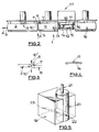
- a compact in-line turning unit 1 for positioning between a wrapping machine for individual, elongate confectionery bars b and a further wrapping machine arranged to group together a plurality of the wrapped bars and to wrap the group in an overall wrapping.
- the wrapping machine for individual bars has an out-feed conveyor, not shown, which conveys the bars with their longitudinal axes on the longitudinal axis of the out-feed conveyor.
- the wrapping machine out-feed conveyor feeds the first horizontal belt conveyor 2, as indicated by arrow A in Figure 2, with the spaced-apart wrapped bars, and these are projected by the out-feed end 4 of the conveyor 2 onto the in-feed end 5 of a second horizontal belt conveyor 6 which is arranged with its upper surface a few mm below the level of the upper surface of the first conveyor 2, as shown in Figure 3. Whilst the bars are in flight between leaving the conveyor 2 and landing on conveyor 6 they are each subjected to a controlled blast of air by an air jet 7 positioned above the in-feed end of second conveyor 6, the air jet 7 being controlled by a solenoid-operated valve 8.
- the air jet 7 is directed substantially horizontally and transversely of the second conveyor 6 and the air blast is timed such that it strikes only the leading or trailing half of the bar whilst the bar is in flight, depending on the required direction of turn.
- the timing signal for the air blast is obtained from photo-sensor arrays 9, 10 and from a shaft encoder associated with the drive to first conveyor 2. It will be appreciated that the shaft encoder signals will be a measure of the speed of the bar when it is projected onto the second conveyor 6, and that the array 10 will provide a time reference.
- the multiple signals produced by the various sensors of array 10 are used to provide immunity against false triggering of air jet 7.
- the light sources for the array 10 are carred by a yoke 101.
- the generally horizontal direction of the air jet 7 is such as to cause a bar in flight to be pivoted about a vertical axis through its centre of gravity. This provides a precise degree of turning when the bars are fed substantially to the centre-line of the conveyor 2.
- the sensor array 9 is used to monitor the lengths of the wrapped bars coming from the wrapping machine, and any out-of-specification bars are arranged to be diverted from conveyor 2 by applying air to a bank of air jets 3. Also, if a downstream problem is detected, the air jets 3 can again be operated to arrest the flow of bars.
- the air jet 7 is arranged to turn the bars by about 30° from the longitudinal axis of the conveyor 6, but angles of up to about 45° would be possible. The bars then proceed along conveyor 6 at this angle, as shown in Figure 1.
- the speed of the first conveyor 2 can be adjusted to alter the spacing of the bars if desired.
- the operation of the air turner is subject to automatic long-term correction by the control system based on measurements of the achieved turn by a further sensor array, not shown, on conveyor 18.
- FIG. 5 shows schematically a suitable rotary valve assembly for providing the burst of compressed air to air jet 7.
- the valve assembly comprises an aluminium valve block 19, the front right hand side having been cut away in Figure 5, formed with a cylindrical bore in which a cylindrical aluminium valve rotor 20 of low inertia is freely rotatable.
- the rotor 20 is of 15 mm diameter, and a substantial radial clearance of about 0.1 mm is provided between rotor 20 and block 19 to avoid rubbing contact, permanent leakage of air through this clearance providing an air-cushion to facilitate rapid response of the rotor to turning forces applied by a high speed drive motor, not shown, coupled to rotor shaft 21.
- the drive motor is capable of rapidly turning the valve rotor 20 from the on position shown in Figure 5, in which a transverse bore 22 in the rotor is aligned with an air supply bore 23 and an air delivery bore, not shown, in block 19, through an angle of about 10° to an off-position.
- the air delivery bore is connected directly to air jet 7.
- a pair of horizontal diverging cord conveyors 11, 12, the differential speed conveyors, have their upper cord runs level with the upper surface of the belt of second conveyor 6 and extending from closely adjacent the out-feed end 13 of second conveyor 6.
- the upper runs of cords of conveyors 11, 12 are supported on a horizontal support plate 14 having a central elongate aperture 15, beneath which is located a photoelectric sensor array 16.
- the cords of the differential speed conveyors 11, 12 are independently-driven such that a speed differential can be given to the cords.
- the cord 11 is driven by the drive to second conveyor 6 such that it is in synchronism therewith, to receive the leading end of the spaced-apart angled bars coming from second conveyor 6, to facilitate a smooth transfer of the angled bars onto the differential speed conveyor assembly 17 comprised by conveyors 11, 12.
- At transfer the conveyor 12 is running at a nominal speed faster than that of conveyor 11 by about 20%.
- the speed of the conveyor 12 is controlled such that the individual bar being conveyed along assembly 17 is turned to a 90° position with respect to the longitudinal axis of assembly 17 by the time that the bar reaches the out-feed end of assembly 17, where it is transferred to a transfer belt conveyor 18.
- a fast-response motor is used to drive the cord of conveyor 12, and the instantaneous speed of the cord is precisely controlled to achieve the required transverse orientation of the bar.
- the sensor array 16 comprises a line of photoelectric sensors extending transversely of the assembly 17 and is used to measure precisely the actual angular orientation of the bar as it passes over the sensor 16, light emitters for the array 16 being mounted on a vertically aligned yoke 161. The amount of corrective turning that is required to bring the bar to a transverse position is then computed, and a speed profile for the conveyor 12 is then computed and applied to the drive to conveyor 12. Since the sensor array 16 is positioned after the transfer from conveyor 6 to the conveyors 11, 12 has been completed, an accurate assessment of the turned condition and the need for further turning is made.
- the length of the conveyors 11, 12 will usually be such that they will hold more than one bar.
- the control system tracks the bars as they progress along the conveyors 11, 12 using encoders fitted to the drive motors, and applies corrections as required to the leading bar. As that bar transfers to conveyor 18 the next bar on the belts is examined and action is commenced to achieve the desired angle of turn.
- the degree of correction that can be applied to a bar will be limited by the maximum acceleration that is possible before the bar rolls or slips on the correcting cord. In addition a correction that would cause the succeeding bar to be badly misplaced is also prevented by the control system from being applied.
- the assembly 17 is capable of handling bars fed to it which may vary slightly in angular orientation, the speed of conveyor 12 being altered accordingly to compensate.
- a microprocessor control system is employed to control the various functions and the functional layout of the control system is shown in Figure 6.
- the transverse spacing of the cords of the differential speed conveyors 11, 12 at the in-feed end is sufficient to ensure that both ends of the angled bars fed by second conveyor 6 are supported by the cords.
- the cords diverge at approximately the same rate as the ends of the bar move transversely of the conveyor assembly 17 as the bar is turned to a fully transverse orientation, this arrangement minimising any transverse movement of each bar end relative to the respective cord.
- This diverging of the conveyors 11, 12 helps to provide accurate transverse positioning of the bars fed to transfer conveyor 18, and thereby avoids the need for any mechanical pusher to position the bars transversely, which might otherwise damage the bars.
- the apparatus shown is very compact, about 2 m long, as compared with known turning assemblies. This is partly due to the in-line arrangement of the conveyors and partly due to the compactness of the individual turning units results from the turning techniques employed.
- microprocessor control enables the incorporation of the self-clearing features discussed for faulty bars, and so these bars will not be passed to the further wrapping machine where they would cause jams and stoppages.
Claims (11)
- Un appareil de convoyage pour retourner en objet oblong (b) comprenant des premiers et seconds convoyeurs à courroie sensiblement alignés (2,6), des moyens de retournement fait pour retourner un objet lorsque cet objet passe du premier convoyeur (2) au second convoyeur (6), caractérisé en ce que le premier convoyeur (2) est agencé pour projeter des objets à travers l'air sur le second convoyeur (6), et en ce que les moyens de retournement sont des moyens de soufflage à gaz (7) agencé de façon à diriger un souffle de gaz (7) sur un objet (b) projeté par le premier convoyeur tandis que l'objet est en train de voler entre les deux convoyeurs (2,6), la direction du souffle de gaz étant sensiblement dans un plan parallèle aux surfaces de convoyage des convoyeurs de telle façon que l'objet soit retourné par le souffle autour d'un axe qui est sensiblement normal aux surfaces de convoyage des convoyeurs.
- Un appareil de convoyage tel que revendiqué dans la revendication 1, dans lequel l'extrémité de sortie du premier convoyeur (2) est situé à une altitude supérieure à celle de l'extrémité d'entrée du second convoyeur (6), de telle façon que les objets tombent légèrement en passant entre les convoyeurs.
- Un appareil de convoyage tel que revendiqué à la revendication 1 ou à la revendication 2, comprenant des moyens de chronométrie (10, 10¹) agencé de façon à surveiller ou suivre le déplacement vers l'avant de l'objet et à commander l'instant de soufflage soit sur la partie avant de l'objet soit sur la partie arrière de l'objet.
- Un appareil de convoyage tel que revendiqué à la revendication 3, dans lequel les moyens de soufflage de gaz (7) comportent un jet de gaz alimenté en gaz par une valve rotative (19, 20), dans lequel également la valve rotative comporte un rotor de valve (20) qui est susceptible de tourner avec un jeu sensiblement radial dans un alésage d'un bloc de valve (19), de manière à ce qu'on réalise, en service un coussin de gaz entre le rotor et le bloc pour réduire la résistance à la rotation du rotor.
- Un appareil de convoyage tel que revendiqué dans l'une quelconque des revendications précédentes, comprenant une paire de convoyeurs à courroie placée côte à côte à des vitesses différentes (11,12), agencés pour recevoir les objets du second convoyeur, des moyens (16, 16¹) pour mesurer l'orientation d'un objet qui se trouve à l'extrémité d'entrée des convoyeurs à vitesse différentielle, ou qui lui est adjacent et des moyens de commande sensible aux moyens de mesure (16,16¹) pour commander les différences de vitesse entre les convoyeurs à vitesse différentielle, de façon à obtenir une orientation prédéterminée de l'objet à l'extrémité de sortie des convoyeurs à vitesse différentielle.
- Un appareil de convoyage tel que revendiqué à la revendication 5, dans lequel on fait varier la vitesse d'une seule (11) des courroies à vitesse différentielle, et la vitesse de l'autre courroie à vitesse différentielle (12) est synchronisé avec la vitesse du second convoyeur.
- Un appareil de convoyage tel que revendiqué à la revendication 5 ou à la revendication 6, dans lequel les courroies à vitesse différentielle sont des cordes.
- Un appareil de convoyage tel que revendiqué dans l'une quelconque des revendications 5 à 7, dans lequel les trajets de convoyage des courroies à vitesse différentielle sont divergentes l'une de l'autre dans la direction de convoyage.
- Un procédé de retournement d'un objet oblong lorsque l'objet est transféré d'un premier convoyeur à courroie (2) à un second convoyeur à courroie (6) sensiblement aligné, caractérisé en ce qu'il comporte les étapes consistant à projeter l'objet à travers l'air à partir d'une extrémité du premier convoyeur (2) vers le second convoyeur, et à envoyer un souffle dirigé de gaz sec pendant une durée sur l'objet projeté sur le premier convoyeur tandis que l'objet est en vol entre les deux convoyeurs, le souffle de gaz étant dirigé sensiblement dans un plan parallèle aux surfaces supérieures des convoyeurs.
- Le procédé de la revendication 9, caractérisé en ce que l'objet est initialement sensiblement aligné sur l'axe du premier convoyeur, l'objet est retourné sous un angle aigu par le souffle de gaz et est ensuite retourné sous un autre angle aigu par une paire de convoyeurs à vitesse différentielle, (11, 12) de telle façon que l'objet se trouve disposé de façon sensiblement transversale par rapport à l'axe longitudinal des convoyeurs à vitesse différentielle à leur extrémité de sortie.
- Le procédé de la revendication 9 ou de la revendication 10, caractérisé en ce que l'objet est une barre de produit de confiserie.
Applications Claiming Priority (2)
| Application Number | Priority Date | Filing Date | Title |
|---|---|---|---|
| GB909011751A GB9011751D0 (en) | 1990-05-25 | 1990-05-25 | Conveying apparatus |
| GB9011751 | 1990-05-25 |
Publications (2)
| Publication Number | Publication Date |
|---|---|
| EP0458580A1 EP0458580A1 (fr) | 1991-11-27 |
| EP0458580B1 true EP0458580B1 (fr) | 1994-07-27 |
Family
ID=10676572
Family Applications (1)
| Application Number | Title | Priority Date | Filing Date |
|---|---|---|---|
| EP91304561A Expired - Lifetime EP0458580B1 (fr) | 1990-05-25 | 1991-05-21 | Appareil et procédé de convoyage |
Country Status (4)
| Country | Link |
|---|---|
| US (1) | US5172800A (fr) |
| EP (1) | EP0458580B1 (fr) |
| DE (1) | DE69103084T2 (fr) |
| GB (1) | GB9011751D0 (fr) |
Families Citing this family (11)
| Publication number | Priority date | Publication date | Assignee | Title |
|---|---|---|---|---|
| DE19906882C2 (de) * | 1999-02-19 | 2001-01-25 | Seidel Helmut | Verfahren und Vorrichtung zum Drehen eines Gegenstandes, insbesondere zum Drehen einer quaderförmigen Faltschachtel |
| US6257824B1 (en) * | 1999-10-05 | 2001-07-10 | Visteon Global Technologies, Inc. | Fin alternating and delivering apparatus |
| US6874615B2 (en) * | 2003-06-06 | 2005-04-05 | David M Fallas | Conveyor chute |
| US7644558B1 (en) | 2006-10-26 | 2010-01-12 | Fallas David M | Robotic case packing system |
| GB2490330A (en) * | 2011-04-26 | 2012-10-31 | De Beers Centenary AG | Automatic gemstone orientation apparatus |
| US8997438B1 (en) | 2012-09-18 | 2015-04-07 | David M. Fallas | Case packing system having robotic pick and place mechanism and dual dump bins |
| DE102014106235A1 (de) * | 2014-05-05 | 2015-11-05 | Wood-Flame Gmbh | Verfahren und Vorrichtung zur Qualitätskontrolle von stetig gefördertem Stückgut |
| US9469488B1 (en) * | 2015-12-10 | 2016-10-18 | SEETECH Systems, Inc. | Article conveyor system with automatic ejection of fallen and tipped articles |
| DE102017120730A1 (de) * | 2017-09-08 | 2019-03-14 | Khs Gmbh | Vorrichtung und Verfahren zur Ausrichtung von Gebinden |
| CN109955153B (zh) * | 2019-04-19 | 2023-10-10 | 米巴精密零部件(中国)有限公司 | 一种翻转定位装置及其工作方法 |
| US10961059B2 (en) * | 2019-08-27 | 2021-03-30 | Siemens Logistics Llc | Parcel processing systems and methods using selective parcel rotation |
Family Cites Families (10)
| Publication number | Priority date | Publication date | Assignee | Title |
|---|---|---|---|---|
| US3462001A (en) * | 1967-05-26 | 1969-08-19 | Fmc Corp | Container orienting apparatus |
| CH546197A (de) * | 1971-09-14 | 1974-02-28 | Fehr & Reist Ag | Wendefoerderer fuer flaechengebilde, insbesondere druckprodukte. |
| CH551329A (de) * | 1972-05-03 | 1974-07-15 | Sig Schweiz Industrieges | Vorrichtung zum trennen und ausrichten von laenglichen gegenstaenden, die ungeordnet auf einem endlosen foerderband aufgebracht sind. |
| US3954171A (en) * | 1974-07-11 | 1976-05-04 | Monsanto Company | Linearly disposed method and apparatus for orienting articles in a pre-selected end-to-end position |
| US4135616A (en) * | 1977-05-06 | 1979-01-23 | Guntert & Pellaton, Inc. | Method and apparatus for stacking pasta strips |
| JPS5589125A (en) * | 1978-12-27 | 1980-07-05 | Saitou Koken:Kk | Method and device for arrangement of spoon for ice-cream |
| US4608646A (en) * | 1984-10-25 | 1986-08-26 | Programmable Orienting Systems, Inc. | Programmable parts feeder |
| DE3673307D1 (de) * | 1985-10-09 | 1990-09-13 | Sig Schweiz Industrieges | Vorrichtung zum vereinzeln und zum zufuehren von laenglichen nahrungsmittelprodukten zu einer verpackungsmaschine. |
| DE3718206A1 (de) * | 1987-05-29 | 1988-12-15 | Will E C H Gmbh & Co | Vorrichtung zum foerdern und drehen von papierstapeln |
| DE3730307C2 (de) * | 1987-09-10 | 1996-05-23 | Heinz Meitinger | Zuführeinrichtung mit Vorratskammern |
-
1990
- 1990-05-25 GB GB909011751A patent/GB9011751D0/en active Pending
-
1991
- 1991-05-21 DE DE69103084T patent/DE69103084T2/de not_active Expired - Fee Related
- 1991-05-21 EP EP91304561A patent/EP0458580B1/fr not_active Expired - Lifetime
- 1991-05-23 US US07/704,349 patent/US5172800A/en not_active Expired - Fee Related
Also Published As
| Publication number | Publication date |
|---|---|
| DE69103084T2 (de) | 1994-11-17 |
| US5172800A (en) | 1992-12-22 |
| DE69103084D1 (de) | 1994-09-01 |
| GB9011751D0 (en) | 1990-07-18 |
| EP0458580A1 (fr) | 1991-11-27 |
Similar Documents
| Publication | Publication Date | Title |
|---|---|---|
| US5944165A (en) | Lane distribution apparatus | |
| US7021450B2 (en) | Device and method to correct uneven spacing of successive articles | |
| EP0458580B1 (fr) | Appareil et procédé de convoyage | |
| US9409724B2 (en) | Device and method for conveying lumpy products | |
| EP1490280B1 (fr) | Dispositif de transfert retractable pour un appareil de comptage | |
| US6053304A (en) | Storage unit with rates of advance dependent on upstream and downstream rates | |
| US5782332A (en) | Device and corresponding method for grouping together random product flows into a single path according to a pre-established and adjustable rate of advance | |
| NL8702193A (nl) | Computergeregelde licht-contactaanvoerder. | |
| NL8601523A (nl) | Computergestuurde. contactloze toevoerinrichting. | |
| EP0124177B1 (fr) | Dispositif pour le transfert d'une rangée d'articles, délivrés par un convoyeur à bande, vers un autre convoyeur à bande placé transversalement | |
| GB2065055A (en) | Device on a packaging machine for forming upstanding groups of flat articles | |
| GB2084101A (en) | Collating conveyor system | |
| US6550608B1 (en) | Carton feeding system for packaging machine | |
| US5762175A (en) | Apparatus for the ordered transportation of packs | |
| CA1203783A (fr) | Emballeuse mecanique de bonbons en forme de batons | |
| EP1682435B1 (fr) | Dipositif de rotation d'articles | |
| US6106219A (en) | Stack forming and conveying apparatus | |
| US4793461A (en) | Container feed apparatus | |
| US5460272A (en) | Apparatus for sorting objects, especially those of flat shape | |
| GB2129754A (en) | Feeding apparatus and the method | |
| US4548313A (en) | Device for forming batches of box shaped products in side by side rows in particular out of supply line infed parcels liable to lose their shape | |
| US4773524A (en) | Transfer arrangement | |
| US3402803A (en) | Article conveying, collecting and metering method and apparatus | |
| CA1128560A (fr) | Mecanisme d'acheminement d'articles | |
| EP0186986B1 (fr) | Convoyeur |
Legal Events
| Date | Code | Title | Description |
|---|---|---|---|
| PUAI | Public reference made under article 153(3) epc to a published international application that has entered the european phase |
Free format text: ORIGINAL CODE: 0009012 |
|
| AK | Designated contracting states |
Kind code of ref document: A1 Designated state(s): CH DE DK FR GB IT LI SE |
|
| 17P | Request for examination filed |
Effective date: 19920513 |
|
| 17Q | First examination report despatched |
Effective date: 19921209 |
|
| GRAA | (expected) grant |
Free format text: ORIGINAL CODE: 0009210 |
|
| RAP1 | Party data changed (applicant data changed or rights of an application transferred) |
Owner name: APV CORPORATION LIMITED |
|
| AK | Designated contracting states |
Kind code of ref document: B1 Designated state(s): CH DE DK FR GB IT LI SE |
|
| PG25 | Lapsed in a contracting state [announced via postgrant information from national office to epo] |
Ref country code: LI Effective date: 19940727 Ref country code: DK Effective date: 19940727 Ref country code: CH Effective date: 19940727 |
|
| ET | Fr: translation filed | ||
| REF | Corresponds to: |
Ref document number: 69103084 Country of ref document: DE Date of ref document: 19940901 |
|
| ITF | It: translation for a ep patent filed |
Owner name: ING. A. GIAMBROCONO & C. S.R.L. |
|
| PG25 | Lapsed in a contracting state [announced via postgrant information from national office to epo] |
Ref country code: SE Effective date: 19941027 |
|
| REG | Reference to a national code |
Ref country code: CH Ref legal event code: PL |
|
| PLBE | No opposition filed within time limit |
Free format text: ORIGINAL CODE: 0009261 |
|
| STAA | Information on the status of an ep patent application or granted ep patent |
Free format text: STATUS: NO OPPOSITION FILED WITHIN TIME LIMIT |
|
| 26N | No opposition filed | ||
| PGFP | Annual fee paid to national office [announced via postgrant information from national office to epo] |
Ref country code: FR Payment date: 19970228 Year of fee payment: 7 |
|
| PGFP | Annual fee paid to national office [announced via postgrant information from national office to epo] |
Ref country code: DE Payment date: 19970424 Year of fee payment: 7 |
|
| PGFP | Annual fee paid to national office [announced via postgrant information from national office to epo] |
Ref country code: GB Payment date: 19970430 Year of fee payment: 7 |
|
| PG25 | Lapsed in a contracting state [announced via postgrant information from national office to epo] |
Ref country code: GB Free format text: LAPSE BECAUSE OF NON-PAYMENT OF DUE FEES Effective date: 19980521 |
|
| PG25 | Lapsed in a contracting state [announced via postgrant information from national office to epo] |
Ref country code: FR Free format text: LAPSE BECAUSE OF NON-PAYMENT OF DUE FEES Effective date: 19980531 |
|
| GBPC | Gb: european patent ceased through non-payment of renewal fee |
Effective date: 19980521 |
|
| PG25 | Lapsed in a contracting state [announced via postgrant information from national office to epo] |
Ref country code: DE Free format text: LAPSE BECAUSE OF NON-PAYMENT OF DUE FEES Effective date: 19990302 |
|
| REG | Reference to a national code |
Ref country code: FR Ref legal event code: ST |
|
| PG25 | Lapsed in a contracting state [announced via postgrant information from national office to epo] |
Ref country code: IT Free format text: LAPSE BECAUSE OF NON-PAYMENT OF DUE FEES;WARNING: LAPSES OF ITALIAN PATENTS WITH EFFECTIVE DATE BEFORE 2007 MAY HAVE OCCURRED AT ANY TIME BEFORE 2007. THE CORRECT EFFECTIVE DATE MAY BE DIFFERENT FROM THE ONE RECORDED. Effective date: 20050521 |