EP0457917A1 - Method of molding a premolded body of fiber-reinforced composite material - Google Patents
Method of molding a premolded body of fiber-reinforced composite material Download PDFInfo
- Publication number
- EP0457917A1 EP0457917A1 EP91900325A EP91900325A EP0457917A1 EP 0457917 A1 EP0457917 A1 EP 0457917A1 EP 91900325 A EP91900325 A EP 91900325A EP 91900325 A EP91900325 A EP 91900325A EP 0457917 A1 EP0457917 A1 EP 0457917A1
- Authority
- EP
- European Patent Office
- Prior art keywords
- preform
- heating
- composite material
- gas
- heated
- Prior art date
- Legal status (The legal status is an assumption and is not a legal conclusion. Google has not performed a legal analysis and makes no representation as to the accuracy of the status listed.)
- Granted
Links
Images


Classifications
-
- B—PERFORMING OPERATIONS; TRANSPORTING
- B29—WORKING OF PLASTICS; WORKING OF SUBSTANCES IN A PLASTIC STATE IN GENERAL
- B29C—SHAPING OR JOINING OF PLASTICS; SHAPING OF MATERIAL IN A PLASTIC STATE, NOT OTHERWISE PROVIDED FOR; AFTER-TREATMENT OF THE SHAPED PRODUCTS, e.g. REPAIRING
- B29C35/00—Heating, cooling or curing, e.g. crosslinking or vulcanising; Apparatus therefor
- B29C35/02—Heating or curing, e.g. crosslinking or vulcanizing during moulding, e.g. in a mould
- B29C35/0222—Heating or curing, e.g. crosslinking or vulcanizing during moulding, e.g. in a mould the curing continuing after removal from the mould
-
- B—PERFORMING OPERATIONS; TRANSPORTING
- B29—WORKING OF PLASTICS; WORKING OF SUBSTANCES IN A PLASTIC STATE IN GENERAL
- B29B—PREPARATION OR PRETREATMENT OF THE MATERIAL TO BE SHAPED; MAKING GRANULES OR PREFORMS; RECOVERY OF PLASTICS OR OTHER CONSTITUENTS OF WASTE MATERIAL CONTAINING PLASTICS
- B29B13/00—Conditioning or physical treatment of the material to be shaped
- B29B13/02—Conditioning or physical treatment of the material to be shaped by heating
-
- B—PERFORMING OPERATIONS; TRANSPORTING
- B29—WORKING OF PLASTICS; WORKING OF SUBSTANCES IN A PLASTIC STATE IN GENERAL
- B29C—SHAPING OR JOINING OF PLASTICS; SHAPING OF MATERIAL IN A PLASTIC STATE, NOT OTHERWISE PROVIDED FOR; AFTER-TREATMENT OF THE SHAPED PRODUCTS, e.g. REPAIRING
- B29C35/00—Heating, cooling or curing, e.g. crosslinking or vulcanising; Apparatus therefor
- B29C35/02—Heating or curing, e.g. crosslinking or vulcanizing during moulding, e.g. in a mould
- B29C35/04—Heating or curing, e.g. crosslinking or vulcanizing during moulding, e.g. in a mould using liquids, gas or steam
-
- B—PERFORMING OPERATIONS; TRANSPORTING
- B29—WORKING OF PLASTICS; WORKING OF SUBSTANCES IN A PLASTIC STATE IN GENERAL
- B29C—SHAPING OR JOINING OF PLASTICS; SHAPING OF MATERIAL IN A PLASTIC STATE, NOT OTHERWISE PROVIDED FOR; AFTER-TREATMENT OF THE SHAPED PRODUCTS, e.g. REPAIRING
- B29C35/00—Heating, cooling or curing, e.g. crosslinking or vulcanising; Apparatus therefor
- B29C35/02—Heating or curing, e.g. crosslinking or vulcanizing during moulding, e.g. in a mould
- B29C35/12—Dielectric heating
-
- B—PERFORMING OPERATIONS; TRANSPORTING
- B29—WORKING OF PLASTICS; WORKING OF SUBSTANCES IN A PLASTIC STATE IN GENERAL
- B29C—SHAPING OR JOINING OF PLASTICS; SHAPING OF MATERIAL IN A PLASTIC STATE, NOT OTHERWISE PROVIDED FOR; AFTER-TREATMENT OF THE SHAPED PRODUCTS, e.g. REPAIRING
- B29C43/00—Compression moulding, i.e. applying external pressure to flow the moulding material; Apparatus therefor
- B29C43/32—Component parts, details or accessories; Auxiliary operations
- B29C43/52—Heating or cooling
-
- B—PERFORMING OPERATIONS; TRANSPORTING
- B29—WORKING OF PLASTICS; WORKING OF SUBSTANCES IN A PLASTIC STATE IN GENERAL
- B29C—SHAPING OR JOINING OF PLASTICS; SHAPING OF MATERIAL IN A PLASTIC STATE, NOT OTHERWISE PROVIDED FOR; AFTER-TREATMENT OF THE SHAPED PRODUCTS, e.g. REPAIRING
- B29C70/00—Shaping composites, i.e. plastics material comprising reinforcements, fillers or preformed parts, e.g. inserts
- B29C70/04—Shaping composites, i.e. plastics material comprising reinforcements, fillers or preformed parts, e.g. inserts comprising reinforcements only, e.g. self-reinforcing plastics
- B29C70/28—Shaping operations therefor
- B29C70/40—Shaping or impregnating by compression not applied
- B29C70/42—Shaping or impregnating by compression not applied for producing articles of definite length, i.e. discrete articles
- B29C70/46—Shaping or impregnating by compression not applied for producing articles of definite length, i.e. discrete articles using matched moulds, e.g. for deforming sheet moulding compounds [SMC] or prepregs
-
- B—PERFORMING OPERATIONS; TRANSPORTING
- B29—WORKING OF PLASTICS; WORKING OF SUBSTANCES IN A PLASTIC STATE IN GENERAL
- B29C—SHAPING OR JOINING OF PLASTICS; SHAPING OF MATERIAL IN A PLASTIC STATE, NOT OTHERWISE PROVIDED FOR; AFTER-TREATMENT OF THE SHAPED PRODUCTS, e.g. REPAIRING
- B29C35/00—Heating, cooling or curing, e.g. crosslinking or vulcanising; Apparatus therefor
- B29C35/02—Heating or curing, e.g. crosslinking or vulcanizing during moulding, e.g. in a mould
- B29C35/08—Heating or curing, e.g. crosslinking or vulcanizing during moulding, e.g. in a mould by wave energy or particle radiation
- B29C35/0805—Heating or curing, e.g. crosslinking or vulcanizing during moulding, e.g. in a mould by wave energy or particle radiation using electromagnetic radiation
- B29C2035/0855—Heating or curing, e.g. crosslinking or vulcanizing during moulding, e.g. in a mould by wave energy or particle radiation using electromagnetic radiation using microwave
-
- B—PERFORMING OPERATIONS; TRANSPORTING
- B29—WORKING OF PLASTICS; WORKING OF SUBSTANCES IN A PLASTIC STATE IN GENERAL
- B29C—SHAPING OR JOINING OF PLASTICS; SHAPING OF MATERIAL IN A PLASTIC STATE, NOT OTHERWISE PROVIDED FOR; AFTER-TREATMENT OF THE SHAPED PRODUCTS, e.g. REPAIRING
- B29C2791/00—Shaping characteristics in general
- B29C2791/001—Shaping in several steps
-
- B—PERFORMING OPERATIONS; TRANSPORTING
- B29—WORKING OF PLASTICS; WORKING OF SUBSTANCES IN A PLASTIC STATE IN GENERAL
- B29C—SHAPING OR JOINING OF PLASTICS; SHAPING OF MATERIAL IN A PLASTIC STATE, NOT OTHERWISE PROVIDED FOR; AFTER-TREATMENT OF THE SHAPED PRODUCTS, e.g. REPAIRING
- B29C35/00—Heating, cooling or curing, e.g. crosslinking or vulcanising; Apparatus therefor
- B29C35/02—Heating or curing, e.g. crosslinking or vulcanizing during moulding, e.g. in a mould
- B29C35/04—Heating or curing, e.g. crosslinking or vulcanizing during moulding, e.g. in a mould using liquids, gas or steam
- B29C35/045—Heating or curing, e.g. crosslinking or vulcanizing during moulding, e.g. in a mould using liquids, gas or steam using gas or flames
-
- B—PERFORMING OPERATIONS; TRANSPORTING
- B29—WORKING OF PLASTICS; WORKING OF SUBSTANCES IN A PLASTIC STATE IN GENERAL
- B29C—SHAPING OR JOINING OF PLASTICS; SHAPING OF MATERIAL IN A PLASTIC STATE, NOT OTHERWISE PROVIDED FOR; AFTER-TREATMENT OF THE SHAPED PRODUCTS, e.g. REPAIRING
- B29C43/00—Compression moulding, i.e. applying external pressure to flow the moulding material; Apparatus therefor
-
- Y—GENERAL TAGGING OF NEW TECHNOLOGICAL DEVELOPMENTS; GENERAL TAGGING OF CROSS-SECTIONAL TECHNOLOGIES SPANNING OVER SEVERAL SECTIONS OF THE IPC; TECHNICAL SUBJECTS COVERED BY FORMER USPC CROSS-REFERENCE ART COLLECTIONS [XRACs] AND DIGESTS
- Y10—TECHNICAL SUBJECTS COVERED BY FORMER USPC
- Y10S—TECHNICAL SUBJECTS COVERED BY FORMER USPC CROSS-REFERENCE ART COLLECTIONS [XRACs] AND DIGESTS
- Y10S264/00—Plastic and nonmetallic article shaping or treating: processes
- Y10S264/65—Processes of preheating prior to molding
Definitions
- the present invention relates to a preform of a fiber-reinforced composite material comprising a synthetic resin material and reinforcing fibers dispersed therein, and also to a method for molding such preform into a desired shape.
- Composite materials comprising thermosetting or thermoplastic synthetic resins and reinforcing fibers dispersed uniformly therein are superior in physical properties (particularly tensile strength and impact resistance, so are widely used as panel materials, outer plies, container materials, etc.
- preform a sheet-like or agglomerated shape (including a bulky or block-like shape) (hereinafter referred to as "preform"), and the preform is heated before molding. This is a commonly-adopted molding method.
- Sheet-like preforms are widely used because they are advantageous in that they can be easily heated uniformly and are superior in press-moldability.
- sheet-like preforms involve the following drawbacks.
- agglomerated preforms In agglomerated preforms, however, it takes a considerable time to heat them uniformly up to the interior without temperature gradient because agglomerated preforms are thick-walled. More particularly, for heating such agglomerated preforms there usually is employed an infrared heater, an electric heater, or hot air, but all of these methods apply heat from the outside of preforms, so a temperature gradient is formed from the outer surface side toward the center in the preforms, and if the heating speed is too high, the outer peripheral portion will assume an overheated state when the temperature of the central portion has reached an appropriate processing temperature.
- the outer periphery side may be softened to an excessive degree and fluidized, or in the case of an agglomerated preform using a thermosetting resin, secondary hardening on the outer periphery side will proceed. In both cases, the moldability is deteriorated markedly.
- the present invention has been accomplished in view of such problems, and it is the object thereof to provide a molding method wherein in a heating process performed prior to molding there is included a heating step capable of raising the temperature of an agglomerated preform uniformly and efficiently, and also provide a preform of a fiber-reinforced composite material.
- an agglomerated preform of a fiber-reinforced composite material is heated from the interior to raise the temperature of the entire agglomerated preform up to a uniform molding temperature in a short time, thereby reducing or eliminating the difference in temperature between the central side and the exterior side.
- an optional number of gas nozzles are inserted into a preform and heated gas is blown into the preform through the gas nozzles, whereby the heated gas is dispersed uniformly in the preform to raise the temperature of the whole preform uniformly from the interior.
- an optional number of rod-like heaters are inserted into a preform and the temperature of whole preform is raised uniformly from the interior thereof by heating using the rod-like heaters.
- a predetermined amount of a dielectric loss improver is uniformly incorporated beforehand into a preform and the temperature of the entire preform is raised uniformly by utilizing the phenomenon of intermolecular friction which is induced by microwave heating or high-frequency heating through electrode plates.
- a method wherein there is formed a preform of a fiber-reinforced composite material so as to have an optional number of holes and permit the foregoing rod-like heaters or gas nozzles to be inserted into the holes easily, whereby the temperature of the entire preform can be raised more uniformly and efficiently without causing movement or consolidation of material in the preform at the time of inserting the heaters or the like into the holes.
- a predetermined amount of one or more dielectric loss improvers typical of which are silicon carbide, carbon black, rubbery materials, marble, soda glass, water, ethylene glycol, and glycerin, are uniformly incorporated beforehand into a preform of a fiber-reinforced composite material, the heating efficiency in the foregoing microwave heating or high-frequency heating is improved, whereby the temperature the entire preform can be raised uniformly and efficiently.
- Fig. 1 is an explanatory sectional view showing example of a heating apparatus used in the present invention
- the heating apparatus indicated at 1
- a cylindrical casing 2a and a lid 2b mounted for opening and closing (arrow O-C directions) to an opening (an upper opening in the figure) formed on one side of the casing 2a.
- a gas discharge pipe 2c is disposed in the lid 2b.
- an inner cylinder 3 capable of moving axially (in arrow U2-D2 directions) is received in the casing 2a, and a gas supply mechanism 4 which is movable axially (in arrow U1-D1 directions) is provided within the inner cylinder 3.
- a gas storage chamber 4A is formed in the interior of the gas supply mechanism 4, and a plurality of hollow tube-like gas nozzles 5 having such tips are projecting upwards through the inner cylinder 3, with a large number of gas ejection holes 5a being formed in the peripheral wall of each gas nozzle 5.
- a gas supply pipe 4b for the supply of heated inert gas is connected to the gas storage chamber 4A.
- An optional number (including unity) of gas nozzle 5 is provided in accordance with the size of an agglomerated preform B and for insertion into the preform. In the case where plural gas nozzles are used, it is desirable to arrange them at equal intervals. Provided, however, that they may be arranged at optional intervals while simulating the flow of gas in the preform B.
- the gas nozzles illustrated in the figure are straight tube-like, spiral tube-like nozzles may be inserted under rotation into the preform.
- the lid 2b is retracted to its open position, namely, upwards and the gas supply mechanism 4 is moved backward in the arrow D1 direction so that the tips of the gas nozzles 5 are completely retracted into the inner cylinder 3.
- the agglomerated preform B is placed into the casing 2a and the lid 2b is closed.
- heated inert gas is fed into the gas storage chamber 4A through the gas supply pipe 4b and is distributed to the gas nozzles 5, and the gas nozzles 5 are inserted into the preform B while the heated gas is allowed to jet from the gas ejection holes 5a.
- the heated gas is fed continuously or intermittently from the gas supply pipe 4b and is released upward while being dispersed to the interior of the preform B, whereby the preform B is heated uniformly and quickly from the interior thereof.
- the heated gas it is recommended to use an inert gas such as nitrogen gas or argon gas, but when the synthetic resin material used is difficult to undergo an oxidative deterioration, there may be used heated air for example.
- the gas which has passed through the preform B is collected in a chamber 2A formed in the interior of the lid 2b and is discharged from the discharge pipe 2c.
- the size of the chamber 2A can be set freely.
- the lid 2b When the whole of the preform B has been heated to a predetermined temperature in the above manner, the lid 2b is opened, the inner cylinder 3 is moved up in the direction of arrow U2, the preform B is discharged from the upper portion of the casing 2a and is conveyed to a molding apparatus such as a pressing apparatus for example.
- Fig. 2 is a flowchart showing an example of supplying heated gas to a plurality of heating apparatus 1
- the gas fed from a gas supply source 15 is pressurized by means of a blower 12 and them fed to a heater 11, in which the gas is heated up to a predetermined temperature (e.g. 220-240°C), then fed to the gas supply pipe of each heating apparatus 1.
- the used gas collected by the gas discharge pipe of the heating apparatus 1 is once stored in a tank 13, then cooled by a cooler 14 to a temperature at which the blower 12 can such the gas, and thereafter recirculated.
- a blower capable of sucking gas at a temperature of 150°C or so it is not necessary to use the cooler 14.
- the preform B is heated with only heated gas
- the preform is heated auxiliary also from the outer peripheral side, for example by providing a jacket-like heater 9 in the outer peripheral portion of the casing 2a, as indicated with broken lines, or by providing a face-form heater on the upper surface of the inner cylinder 3, the time required for heating can be further shortened.
- a total opening area Sr of the gas ejection holes 5a of the gas nozzles 5 can be selected optionally in accordance with the shape and size of the preform used.
- the above total opening area Sr is not smaller than (1/50) x Sn.
- FIG. 4 there is illustrated a heating apparatus having a structure of preventing the expansion of the preform B, in which pressing plate 6 capable of approaching and leaving the preform B is mounted to the lid 2b so that it can press the upper surface of the preform B received in the casing 2a.
- a large number of through holes are formed in the pressing plate 6, and heated gas passes through the through holes 6a and is collected into a gas discharge pipe 2c.
- some preform B comprises a solid film Bu about 1-3 mm thick formed on the outer surface of the preform and a mixture Bc of a synthetic resin powder and a reinforcing fiber wrapped in the solid film, as shown in Fig. 3.
- a preform B is applied as it is to the heating apparatus 1 shown in Fig. 1, the interior space defined by the solid film Bu of the preform B will be filled with heated gas, resulting in that a weak part of the solid film will burst, thus causing localization of the components of the mixture Bu, or causing a deflected flow of heated gas, leading to loss of uniformity in heating.
- the pressing plate 6 having holes 6a as in Fig.
- each gas nozzle 5 is smaller than the thickness in the height direction of the preform B, it may be rendered longer than the said preform thickness to the extent of its tip projecting from the preform B and breaking through the solid film Bu, thereby improving the passability of heated gas.
- a total opening area Sm of the vent holes B1 be one half or more of the total opening area Sr of the gas ejection holes 5a formed in the gas nozzles 5.
- a vertically movable bottom plate 21 having through holes 21a is provided under a casing 2, and a plurality of rod-like heaters 22 capable of being inserted into and removed from the through holes 21a are disposed under the bottom plate 21.
- a lid member 23 capable of approaching and leaving a preform B received in the casing 2 is provided in the upper portion of the casing, and through holes for insertion therethrough of tips 22a of the rod-like heater 22 are formed in the lid member 23.
- vertically movable upper lid 24 which are fitted on the tips of the rod-like heaters 22 and closes the said through holes.
- the number, thickness and length of the rod-like heaters 22 are selected suitably in accordance with the composite material to be heated.
- the bottom plate 21 is disposed under the casing 2
- a cylindrical preform B is loaded from the upper opening of the casing 2
- the lid member 23 and upper lid 24 are brought down from above until abutment with the upper surface of the preform B.
- the rod-like heaters 22 are moved upward and inserted into the preform B, as shown in Fig. 7.
- the lid member 23 may be disposed in a somewhat higher position to release the expansion of the preform caused by the rod-like heaters 22, or holes B2 corresponding to the rod-like heaters 22 may be formed beforehand in the preform B, as shown in Fig. 8.
- Such a preform B can also be used for the insertion therein of the gas nozzles 5, as described previously.
- the preform B When the rod-like heaters 22 are heated, the preform B is heated from the inner side and there is performed a uniform heating with small temperature gradient in the interior of the preform B. Further, if a sheet-like heater or the like is attached to each of the casing 2, lid member 23 and bottom plate 21, the preform B can be heated uniformly from both the inside and the outside.
- the rod-like heaters 22 are retracted and the preform B is moved to the upper portion of the casing 2 while be sandwiched in between the bottom plate 21 and the lid member 23, then the lid member 23 is retracted. Thereafter, the preform B is fed to a mold machine as in Fig. 9.
- Fig. 9 is a plan view showing a turntable type continuous heating system for heating preforms B continuously by heating apparatus 1 using gas nozzles 5 or rod-like heaters 22.
- a turntable 27 is provided with a plurality of heating apparatus 1 and is rotated by a driving roller 26. Along the outer peripheral edge of the turntable 27 there are disposed the driving roller 26 and guide rollers 25, as well as preform feeding machine A1 and discharging machine A4.
- a preform B is fed to a heating apparatus on the turntable 27 by the feeding machine A1, then in the position A2 the heaters or nozzles are inserted into the preform B, whereby the preform is heated until reaching the position A3.
- the thus-heated preform B is taken out from the heating apparatus 1 by means of the discharging machine A4 is fed thereby to the molding machine.
- the synthetic resin there may be selected a suitable one from among thermosetting resins and thermoplastic resins according to the use and characteristics required.
- examples of employable reinforcing fibers include various metallic fibers and whiskers in addition to most commonly used glass fibers and carbon fibers. If necessary, moreover, in the composite material containing such synthetic resin and reinforcing fiber there may be incorporated filler, antioxidant, stabilizer, coloring agent, plasticizer, antistatic agent, flame-retardant, etc.
- the method for forming the composite material into a preform is not limited at all, either.
- a conventional preforming method may be used as it is or after some modification.
- a composite material a uniform mixture consisting of 60 wt% polypropylene powder and 40 wt% short glass fibers was preformed into a short column shape (200 mm dia. 200 mm long), and a heating experiment was conducted.
- rod-like heaters there were used forty electric heating type rod-like heaters each 16 mm in diameter, and for heating the casing there was used a band heater from the outer surface side, while for heating the lid member and the bottom plate there were used plate heaters.
- the surface temperature was controlled to 260°C.
- nitrogen gas was passed through the heating apparatus 1.
- the temperature of the composite material rose to 220°C in about 2 minutes.
- the temperature difference in the preform was within ⁇ 2.5°C and thus very small. An extremely uniform heating was confirmed.
- heating was made from only the outer surface side of the casing, bottom plate and lid member in the same manner as above except that the heating using the rod-like heaters was omitted.
- the composite material temperature was raised to 220°C at the central portion thereof.
- the temperature of the surface side rose to 260°C and the synthetic resin melted, resulting in that it became difficult to remove the composite material from the heating apparatus.
- the temperature difference of about 40°C between the surface side and the central portion exerted a bad influence on the compression molding in the molding apparatus.
- an agglomerated preform can also be subjected to high-frequency heating (usually 3 to 300 MHz) or microwave heating (usually 300 MHz to 30 GHz) and thereby can be heated uniformly and efficiently.
- microwave heating or high-frequency heating depends much on a dielectric loss of the material to be heated. Also in the present invention it turned out that the effect of the heating was dependent on electrical characteristics of the composite material used and reinforcing fibers incorporated therein as well as other additives if necessary.
- the dielectric loss improver indicates a substance whose dielectric loss angle or dielectric constant is high and which thereby exhibits a high dielectric loss factor.
- Typical examples are silicon carbide, carbon black, various rubbery materials, marble, soda glass, water, ethylene glycol, and glycerin.
- the amount of the dielectric loss improver used be not smaller than 0.1 wt% based on the total weight of the agglomerate preform in both microwave heating and high-frequency heating, whereby it is made possible to enhance the dielectric loss factor of the preform to the extent that the effect of the heating is exhibited satisfactorily.
- the dielectric loss improver is used in an amount exceeding 40 wt% based on the total weight the preform, the strength of the agglomerated preform and that of the resulting molded article will be too much deteriorated.
- a preferred range is 0.1 to 4.5 wt%.
- Fig. 10 is an explanatory side view showing an example of a microwave heating apparatus 30.
- iron pipes 33A, 33A are connected to a heating furnace 34 which incorporates therein a quartz pipe passage 33B and a fan 32, and waveguides 31, 31 are disposed on the heating oven 34.
- Each preform B moves in the direction of arrow through the iron pipe 33A and enters a heating oven 3, in which it is heated by microwaves introduced from the waveguides 31, 31.
- the microwaves are reflected irregularly by the fan 32 and radiated from various angles to the preform B in the heating oven 34.
- the preform B itself moves, for example rotates, vibrates, or ascends and descends, the surface of the preform which undergoes the microwave radiation varies, whereby a more uniform heating is attained.
- the quartz pipe passage 33B does not absorb microwaves, the microwaves are radiated directly to the agglomerated preform B. It is recommended that the interior of the heating oven 34 be purged with an inert gas such as nitrogen gas for example to prevent oxidative deterioration of plastic material and other components.
- Carbon black as a dielectric loss improver was incorporated in a composite material comprising polypropylene powder and glass fibers in such a manner that the proportion of the dielectric loss improver was 0.5 wt%.
- a columnar preform of 200 mm dia. by 200 mm long (weight: 3 kg) was produced and it was then subjected to the radiation of microwaves. At this time, the temperature of the preform rose to 220°C in only 3 minutes, and the temperature difference distribution in the interior of the preform was ⁇ 5°C, thus exhibiting excellent uniformity.
- the mechanical strength of the final product was higher than that of a molded article obtained by using a comparative product which had been subjected to kneading and heating.
- Fig. 12 is a sectional side view showing another example of a microwave heating apparatus and Fig. 13 is a plan view thereof.
- quartz pipe passages 35 in five rows transversely and in two stages vertically, that is, a total of ten rows.
- ten (five rows in two stages) loading air cylinders 39 On an inlet side there are provided ten (five rows in two stages) loading air cylinders 39, and in inlet portions there are provided preform arranging cylinders 37 in two stages vertically for arranging ten agglomerated preforms B.
- On an outlet side there are provided lateral discharge cylinders 36 and longitudinal discharge cylinders 38 each in two stages vertically for discharging the preforms successively.
- Ten agglomerated preforms which have been fed before the inlet portions by the arranging cylinders 37 are inserted, ten as one group, into the quartz pipe passages 35 by means of the loading cylinders 39, in which they are heated under the radiation of microwaves introduced through the waveguides 31.
- the succeeding preforms are loaded successively by repeating the above operation.
- the agglomerated preforms B undergoes microwave heating for a predetermined time while they move through the quartz pipe passages, and when a predetermined temperature has been reached, one group of them are discharged together. Then, before the next discharge is performed, they are conveyed in the direction of arrow by a cooperative operation based on time difference of the lateral and longitudinal cylinders 36, 37.
- agglomerated preforms B are carried on a conveyor belt 45 in the direction of arrow, and electrode plates 41 and 42 for the generation of high frequency are disposed in opposed relation on both sides of the preforms. It is recommended that the heating atmosphere be purged with an inert gas such as nitrogen gas to prevent oxidative deterioration of the synthetic resin and other components.
- an inert gas such as nitrogen gas
- two pairs of such electrode plates are arranged side by side in the longitudinal direction.
- Silicon carbide was incorporated in a composite material consisting of 70 parts by weight polypropylene powder and 30 parts by weight glass fibers in such a manner that the proportion of the silicon carbide was 1.0 wt%.
- a columnar preform of 220 mm dia. by 160 mm long was produced and it was then subjected to the radiation of high frequency of 13 MHz x 3 KW.
- the temperature of the preform rose to 260°C in only 2 minutes, and the temperature difference distribution in the interior of the preform was ⁇ 5°C, thus exhibiting excellent uniformity.
- the heated preform was then molded by means of a compression molding machine.
- the mechanical strength of the final product was higher than that of a molded article obtained by using a comparative product which had been subjected to kneading and heating.
- Example No.3 In place of the silicon carbide used in Example No.3, the proportion of carbon black was incorporated in the composite material. Using the resulting mixture, a columnar preform of 220 mm dia. by 160 mm (weight: 2.25 kg) was produced and it was then subjected to a high-frequency heating at 13 MHz x 6 KW. As a result, the temperature of the preform rose to 220°C in 3 minutes and 30 seconds. At this time, the temperature difference distribution in the interior of the preform was ⁇ 5°C.
- Fig. 15 is an explanatory view showing another working concept of the high-frequency heating method.
- Carbon black was incorporated in a composite material consisting of 65 parts by weight polypropylene and 35 parts by weight glass fibers so that the proportion of the carbon black was 1.0 wt%.
- a columnar preform of 320 mm dia. by 210 mm long was produced. The preform was allowed to travel from left to right on a conveyor belt 45 in Fig.
- Fig. 17 illustrates a high-frequency heating apparatus 40 corresponding to the apparatus shown in Fig. 12, whereby preforms B arranged in five rows, two stages, are heated successively. Electrode plates 41 and 42 are arranged above and below quartz pipe passages 35 so as to wholly cover the quartz pipe passages 35. The preforms are heated in the quartz pipe passages 35 for a predetermined time and then taken out successively.
- the preform B is heated from the interior thereof without using the gas nozzles 5.
- the preform B there is used one having such holes B2 as shown in Fig. 8, or with such holes B2 being closed at one ends.
- These holes are formed by inserting heating needles arranged in conformity with the arrangement of the holes into a preform. It is preferable that the temperature of the needles be below the temperature at which the synthetic resin contained in the preform melts and adheres to the needles.
- the needle heating temperature be set in a temperature range in which the resin used does not adhere to the needles, taking the melting temperature of the resin into account.
- the needles may be held at room temperature, at which temperature, however, the holes may be closed by spring back of the glass fibers. It was found better for the needles to be heated to a certain extent for retaining the holes once formed.
- the preform now having such holes is loaded into the heating apparatus shown in Fig. 4, and nitrogen gas held at 240°C is blown directly (without using gas nozzles) into the holes of the preform for about 2 minutes.
- the heated nitrogen gas thus entered the holes is dispersed to the interior of the preform and thereafter discharged from the upper portion, whereby the preform is heated to about 200-220°C from the interior.
- This method is advantageous in that the heating can be done uniformly in a short time, and that since gas nozzles 5 or rod-like heaters 22 are not used there occurs neither adhesion nor clogging of molten resin, and handling is easy.
- an agglomerated preform containing a synthetic resin and a reinforcing fiber can be heated efficiently in a uniform temperature distribution throughout the whole thereof.
Landscapes
- Physics & Mathematics (AREA)
- Thermal Sciences (AREA)
- Engineering & Computer Science (AREA)
- Mechanical Engineering (AREA)
- Health & Medical Sciences (AREA)
- Oral & Maxillofacial Surgery (AREA)
- Chemical & Material Sciences (AREA)
- Composite Materials (AREA)
- Processing And Handling Of Plastics And Other Materials For Molding In General (AREA)
Abstract
Description
- The present invention relates to a preform of a fiber-reinforced composite material comprising a synthetic resin material and reinforcing fibers dispersed therein, and also to a method for molding such preform into a desired shape.
- Composite materials comprising thermosetting or thermoplastic synthetic resins and reinforcing fibers dispersed uniformly therein are superior in physical properties (particularly tensile strength and impact resistance, so are widely used as panel materials, outer plies, container materials, etc.
- In forming any of such composite materials into a desired shape, it is formed beforehand into a sheet-like or agglomerated shape (including a bulky or block-like shape) (hereinafter referred to as "preform"), and the preform is heated before molding. This is a commonly-adopted molding method.
- Sheet-like preforms are widely used because they are advantageous in that they can be easily heated uniformly and are superior in press-moldability. However, sheet-like preforms involve the following drawbacks.
- ① There has been adopted a method wherein a synthetic resin material is melt-extruded into sheet and impregnation is made while a glass fiber mat or chopped strands are sandwiched in between two such sheets. According to this method, however, there may occur breakage of the reinforcing fibers during the operation, and the manufacturing cost is high.
- ② In forming (hereinafter referred to sometimes as "secondary forming") a sheet-like preform into a desired commodity shape, it is necessary to cut the sheet-like preform according to the desired shape, then laminating such cut preforms onto a metal mold according to a desired thickness and press-molding the laminate, so the molding cost is high.
- Recently, therefore, the demand for agglomerated preforms have been increasing gradually.
- In agglomerated preforms, however, it takes a considerable time to heat them uniformly up to the interior without temperature gradient because agglomerated preforms are thick-walled. More particularly, for heating such agglomerated preforms there usually is employed an infrared heater, an electric heater, or hot air, but all of these methods apply heat from the outside of preforms, so a temperature gradient is formed from the outer surface side toward the center in the preforms, and if the heating speed is too high, the outer peripheral portion will assume an overheated state when the temperature of the central portion has reached an appropriate processing temperature.
- Consequently, for example in the case of an agglomerated preform using a thermoplastic resin, the outer periphery side may be softened to an excessive degree and fluidized, or in the case of an agglomerated preform using a thermosetting resin, secondary hardening on the outer periphery side will proceed. In both cases, the moldability is deteriorated markedly.
- In order to avoid such problems it is required to make the heating rate as low as possible and thereby minimize the foregoing temperature gradient, so a long time is required for raising the temperature up to the molding temperature. As a result, not only the productivity of molded products is deteriorated markedly but also in the case of an agglomerate preform using a thermosetting resin, secondary hardening proceeds and processability deteriorated during such long time.
- The present invention has been accomplished in view of such problems, and it is the object thereof to provide a molding method wherein in a heating process performed prior to molding there is included a heating step capable of raising the temperature of an agglomerated preform uniformly and efficiently, and also provide a preform of a fiber-reinforced composite material.
- According to the present invention, an agglomerated preform of a fiber-reinforced composite material is heated from the interior to raise the temperature of the entire agglomerated preform up to a uniform molding temperature in a short time, thereby reducing or eliminating the difference in temperature between the central side and the exterior side.
- Concrete means will now be described. According to one concrete method, an optional number of gas nozzles are inserted into a preform and heated gas is blown into the preform through the gas nozzles, whereby the heated gas is dispersed uniformly in the preform to raise the temperature of the whole preform uniformly from the interior.
- According to another concrete method, an optional number of rod-like heaters are inserted into a preform and the temperature of whole preform is raised uniformly from the interior thereof by heating using the rod-like heaters.
- According to a further method, a predetermined amount of a dielectric loss improver is uniformly incorporated beforehand into a preform and the temperature of the entire preform is raised uniformly by utilizing the phenomenon of intermolecular friction which is induced by microwave heating or high-frequency heating through electrode plates.
- There also may be adopted a method wherein there is formed a preform of a fiber-reinforced composite material so as to have an optional number of holes and permit the foregoing rod-like heaters or gas nozzles to be inserted into the holes easily, whereby the temperature of the entire preform can be raised more uniformly and efficiently without causing movement or consolidation of material in the preform at the time of inserting the heaters or the like into the holes.
- Further, if a predetermined amount of one or more dielectric loss improvers, typical of which are silicon carbide, carbon black, rubbery materials, marble, soda glass, water, ethylene glycol, and glycerin, are uniformly incorporated beforehand into a preform of a fiber-reinforced composite material, the heating efficiency in the foregoing microwave heating or high-frequency heating is improved, whereby the temperature the entire preform can be raised uniformly and efficiently.
-
- Fig. 1 is an explanatory sectional view showing an example of a heating apparatus using gas nozzles in practising the method of the present invention;
- Fig. 2 is a flow chart showing an example of feeding a heating gas used in the heating apparatus of Fig. 1;
- Fig. 3 is a partially broken away, explanatory view of an agglomerated preform used in the heating apparatus of Fig. 1;
- Figs. 4 and 5 are explanatory sectional views showing other examples heating apparatus using gas nozzles in practising the method of the present invention;
- Figs. 6 and 7 are explanatory sectional views showing a heating process in a heating apparatus using rod-like heaters;
- Fig. 8 is a partially broken away, explanatory view of an agglomerated preform used in the apparatus of Fig. 7;
- Fig. 9 is a plan view showing the whole of a continuous heating system using the heating apparatus illustrated in Fig. 1 or Fig. 7;
- Fig. 10 is an explanatory side view showing an example of a heating apparatus using microwave radiation in practising the method of the present invention;
- Fig. 11 is a graph showing a relation between heating time and reached temperatures in microwave heating;
- Fig. 12 is a sectional side view showing a concrete example of a microwave heating apparatus;
- Fig. 13 is a plan view of Fig. 12;
- Figs. 14 and 15 are schematic explanatory views showing examples of high-frequency heating methods;
- Fig. 16 is a graph showing a relation between heating time and reached temperatures in high-frequency heating; and
- Fig. 17 is a sectional side view showing a concrete example of a high-frequency heating apparatus.
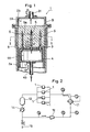
- Referring to Fig. 1, which is an explanatory sectional view showing example of a heating apparatus used in the present invention, the heating apparatus, indicated at 1, is provided with a
cylindrical casing 2a and alid 2b mounted for opening and closing (arrow O-C directions) to an opening (an upper opening in the figure) formed on one side of thecasing 2a. Agas discharge pipe 2c is disposed in thelid 2b. On the other hand, aninner cylinder 3 capable of moving axially (in arrow U₂-D₂ directions) is received in thecasing 2a, and agas supply mechanism 4 which is movable axially (in arrow U₁-D₁ directions) is provided within theinner cylinder 3. Agas storage chamber 4A is formed in the interior of thegas supply mechanism 4, and a plurality of hollow tube-like gas nozzles 5 having such tips are projecting upwards through theinner cylinder 3, with a large number ofgas ejection holes 5a being formed in the peripheral wall of eachgas nozzle 5. Agas supply pipe 4b for the supply of heated inert gas is connected to thegas storage chamber 4A. An optional number (including unity) ofgas nozzle 5 is provided in accordance with the size of an agglomerated preform B and for insertion into the preform. In the case where plural gas nozzles are used, it is desirable to arrange them at equal intervals. Provided, however, that they may be arranged at optional intervals while simulating the flow of gas in the preform B. Although the gas nozzles illustrated in the figure are straight tube-like, spiral tube-like nozzles may be inserted under rotation into the preform. - An example of a method for heating the agglomerated preform B, which is formed of a fiber-reinforced composite material, using the
heating apparatus 1, will be described below in detail. - First, the
lid 2b is retracted to its open position, namely, upwards and thegas supply mechanism 4 is moved backward in the arrow D₁ direction so that the tips of thegas nozzles 5 are completely retracted into theinner cylinder 3. Then, the agglomerated preform B is placed into thecasing 2a and thelid 2b is closed. Subsequently, heated inert gas is fed into thegas storage chamber 4A through thegas supply pipe 4b and is distributed to thegas nozzles 5, and thegas nozzles 5 are inserted into the preform B while the heated gas is allowed to jet from thegas ejection holes 5a. At this time, if the gas is ejected after insertion of thegas nozzles 5, it is likely that thegas ejection holes 5a will be clogged with synthetic resin powder or the like. But, when there is used a preform B not having such likelihood, the ejection of heated gas may be started after insertion of thegas nozzles 5 into the preform B. If holes corresponding to the gas nozzle insertion passages are formed beforehand in the preform (see Fig. 8), that is, if an inner mold corresponding to thegas nozzles 5 is used in forming the preform, not only the insertion of thegas nozzles 5 becomes easier but also there does not arise the problem of partial consolidation of the preform or non-uniform flow of gas which are caused by forced insertion of the gas nozzles. - In the above state, the heated gas is fed continuously or intermittently from the
gas supply pipe 4b and is released upward while being dispersed to the interior of the preform B, whereby the preform B is heated uniformly and quickly from the interior thereof. As the heated gas, it is recommended to use an inert gas such as nitrogen gas or argon gas, but when the synthetic resin material used is difficult to undergo an oxidative deterioration, there may be used heated air for example. - The gas which has passed through the preform B is collected in a
chamber 2A formed in the interior of thelid 2b and is discharged from thedischarge pipe 2c. The size of thechamber 2A can be set freely. - When the whole of the preform B has been heated to a predetermined temperature in the above manner, the
lid 2b is opened, theinner cylinder 3 is moved up in the direction of arrow U₂, the preform B is discharged from the upper portion of thecasing 2a and is conveyed to a molding apparatus such as a pressing apparatus for example. - Referring now to Fig. 2, which is a flowchart showing an example of supplying heated gas to a plurality of
heating apparatus 1, the gas fed from agas supply source 15 is pressurized by means of ablower 12 and them fed to aheater 11, in which the gas is heated up to a predetermined temperature (e.g. 220-240°C), then fed to the gas supply pipe of eachheating apparatus 1. The used gas collected by the gas discharge pipe of theheating apparatus 1 is once stored in atank 13, then cooled by acooler 14 to a temperature at which theblower 12 can such the gas, and thereafter recirculated. When there is used a blower capable of sucking gas at a temperature of 150°C or so, it is not necessary to use thecooler 14. - Although in the apparatus illustrated in Fig. 1 the preform B is heated with only heated gas, if the preform is heated auxiliary also from the outer peripheral side, for example by providing a jacket-
like heater 9 in the outer peripheral portion of thecasing 2a, as indicated with broken lines, or by providing a face-form heater on the upper surface of theinner cylinder 3, the time required for heating can be further shortened. - A total opening area Sr of the gas ejection holes 5a of the
gas nozzles 5 can be selected optionally in accordance with the shape and size of the preform used. Preferably, in order to realize an appropriate heating, when the area of the surface on the gas nozzle insertion side of the preform B (this is also applicable to the opposite-side face in principle) is Sn, the above total opening area Sr is not smaller than (1/50) x Sn. - Referring now to Fig. 4, there is illustrated a heating apparatus having a structure of preventing the expansion of the preform B, in which pressing
plate 6 capable of approaching and leaving the preform B is mounted to thelid 2b so that it can press the upper surface of the preform B received in thecasing 2a. A large number of through holes are formed in thepressing plate 6, and heated gas passes through the throughholes 6a and is collected into agas discharge pipe 2c. - When the preform B is pressed completely from the upper surface thereof as in the example of Fig. 4, it is likely that the flow of heated gas will be obstructed. Therefore, as shown in Fig. 5, it is recommended to provide a
gas sump 6A formed by a slight gap under thepressing plate 6, thereby ensuring the flow of gas while permitting the expansion of the preform B to some extent. - For the purpose of improving handleability, some preform B comprises a solid film Bu about 1-3 mm thick formed on the outer surface of the preform and a mixture Bc of a synthetic resin powder and a reinforcing fiber wrapped in the solid film, as shown in Fig. 3. If such a preform B is applied as it is to the
heating apparatus 1 shown in Fig. 1, the interior space defined by the solid film Bu of the preform B will be filled with heated gas, resulting in that a weak part of the solid film will burst, thus causing localization of the components of the mixture Bu, or causing a deflected flow of heated gas, leading to loss of uniformity in heating. With a view of preventing such inconvenience, there may be used thepressing plate 6 havingholes 6a as in Fig. 4, but if a large number of vent holes B₁ are formed through the solid film Bu in the outer surface as an open surface of the preform B, there is no fear of bursting of the solid film Bu because the heated gas ejected to the interior of the preform B passes through the vent holes B₁. Further, although in the example of Fig. 1 the length of eachgas nozzle 5 is smaller than the thickness in the height direction of the preform B, it may be rendered longer than the said preform thickness to the extent of its tip projecting from the preform B and breaking through the solid film Bu, thereby improving the passability of heated gas. - It is preferable that a total opening area Sm of the vent holes B₁ be one half or more of the total opening area Sr of the
gas ejection holes 5a formed in thegas nozzles 5. As a result, heated gas passes out smoothly from the preform B, so the heating efficiency is improved, and there is no fear of the heated gas pressure becoming too high in the preform B and obstructing the flow of heated gas, nor is there the possibility of the required time for heating becoming longer. Besides, it is no longer possible at all that there will occur a deflecting flow in the heated gas flow which would make the heating distribution non-uniform. - Referring now to Figs. 6 and 7, which are explanatory sectional views showing a
heating apparatus 1 using rod-like heaters, a verticallymovable bottom plate 21 having throughholes 21a is provided under acasing 2, and a plurality of rod-like heaters 22 capable of being inserted into and removed from the throughholes 21a are disposed under thebottom plate 21. Alid member 23 capable of approaching and leaving a preform B received in thecasing 2 is provided in the upper portion of the casing, and through holes for insertion therethrough oftips 22a of the rod-like heater 22 are formed in thelid member 23. Further, on thelid member 23 is disposed vertically movableupper lid 24 which are fitted on the tips of the rod-like heaters 22 and closes the said through holes. The number, thickness and length of the rod-like heaters 22 are selected suitably in accordance with the composite material to be heated. - An example of the method for heating an agglomerated preform using
such heating apparatus 1 will be described below. - First, as shown in Fig. 6, the
bottom plate 21 is disposed under thecasing 2, a cylindrical preform B is loaded from the upper opening of thecasing 2, and thelid member 23 andupper lid 24 are brought down from above until abutment with the upper surface of the preform B. Then, the rod-like heaters 22 are moved upward and inserted into the preform B, as shown in Fig. 7. - Although there is no problem in the case where the preform B is small in the degree of consolidation and still has a margin of compression, when there is used a preform of high density which has been formed at a high pressure, the
lid member 23 may be disposed in a somewhat higher position to release the expansion of the preform caused by the rod-like heaters 22, or holes B₂ corresponding to the rod-like heaters 22 may be formed beforehand in the preform B, as shown in Fig. 8. Such a preform B can also be used for the insertion therein of thegas nozzles 5, as described previously. - When the rod-
like heaters 22 are heated, the preform B is heated from the inner side and there is performed a uniform heating with small temperature gradient in the interior of the preform B. Further, if a sheet-like heater or the like is attached to each of thecasing 2,lid member 23 andbottom plate 21, the preform B can be heated uniformly from both the inside and the outside. - After completion of the heating, the rod-
like heaters 22 are retracted and the preform B is moved to the upper portion of thecasing 2 while be sandwiched in between thebottom plate 21 and thelid member 23, then thelid member 23 is retracted. Thereafter, the preform B is fed to a mold machine as in Fig. 9. - Fig. 9 is a plan view showing a turntable type continuous heating system for heating preforms B continuously by
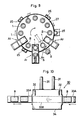
heating apparatus 1 usinggas nozzles 5 or rod-like heaters 22. Aturntable 27 is provided with a plurality ofheating apparatus 1 and is rotated by a drivingroller 26. Along the outer peripheral edge of theturntable 27 there are disposed the drivingroller 26 and guiderollers 25, as well as preform feeding machine A₁ and discharging machine A₄. A preform B is fed to a heating apparatus on theturntable 27 by the feeding machine A₁, then in the position A₂ the heaters or nozzles are inserted into the preform B, whereby the preform is heated until reaching the position A₃. The thus-heated preform B is taken out from theheating apparatus 1 by means of the discharging machine A₄ is fed thereby to the molding machine. - No limitation is placed on the kind of synthetic resin or that of reinforcing fiber as materials of the composite to be used in the above heating method. As the synthetic resin there may be selected a suitable one from among thermosetting resins and thermoplastic resins according to the use and characteristics required. Also, examples of employable reinforcing fibers include various metallic fibers and whiskers in addition to most commonly used glass fibers and carbon fibers. If necessary, moreover, in the composite material containing such synthetic resin and reinforcing fiber there may be incorporated filler, antioxidant, stabilizer, coloring agent, plasticizer, antistatic agent, flame-retardant, etc.
- The method for forming the composite material into a preform is not limited at all, either. A conventional preforming method may be used as it is or after some modification. The following are typical examples of preforming methods.
- ① A synthetic resin powder and short reinforcing fibers are mixed in vapor phase (dry-mixed) together with other additives if necessary and the resulting mixture is charged into a mold, followed by dust molding. In this case, the use of a suitable binder is effective in enhancing moldability and shape retaining property. It is also possible to heat the mixture to a certain extent in the dust molding process, allowing the synthetic resin powder to be melted partially for fusion-bonding and thereby enhancing the shape retaining property.
- ② A synthetic resin powder and short reinforcing fibers are wet-mixed together with other additives if necessary, using water as a mixing medium, then the resulting mixture is formed into a desired shape and dried. Alternatively, the mixture is extruded into a rod-like shape using a plunger extruder, then cut into a suitable length and thereafter dried. Also in this case, a suitable binder may be added, if necessary, for enhancing the moldability and shape retaining property.
- ③ Such a dry mixture as shown in ①) is charged into a plunger extruder, then heated moderately in a discharge die portion to melt the synthetic resin powder partially, and in this state the mixture is extruded.
- Using the
heating apparatus 1 shown in Fig. 7, a composite material a uniform mixture consisting of 60 wt% polypropylene powder and 40 wt% short glass fibers was preformed into a short column shape (200 mm dia. 200 mm long), and a heating experiment was conducted. In this experiment, as rod-like heaters there were used forty electric heating type rod-like heaters each 16 mm in diameter, and for heating the casing there was used a band heater from the outer surface side, while for heating the lid member and the bottom plate there were used plate heaters. In both cases, the surface temperature was controlled to 260°C. For preventing oxidative deterioration of the composite material, nitrogen gas was passed through theheating apparatus 1. - As a result, the temperature of the composite material rose to 220°C in about 2 minutes. The temperature difference in the preform was within ±2.5°C and thus very small. An extremely uniform heating was confirmed.
- By way of comparison, heating was made from only the outer surface side of the casing, bottom plate and lid member in the same manner as above except that the heating using the rod-like heaters was omitted. As a result, about 30 minutes was required for the composite material temperature to rise to 220°C at the central portion thereof. The temperature of the surface side rose to 260°C and the synthetic resin melted, resulting in that it became difficult to remove the composite material from the heating apparatus. The temperature difference of about 40°C between the surface side and the central portion exerted a bad influence on the compression molding in the molding apparatus.
- In the present invention, an agglomerated preform can also be subjected to high-frequency heating (usually 3 to 300 MHz) or microwave heating (usually 300 MHz to 30 GHz) and thereby can be heated uniformly and efficiently.
- Generally, microwave heating or high-frequency heating depends much on a dielectric loss of the material to be heated. Also in the present invention it turned out that the effect of the heating was dependent on electrical characteristics of the composite material used and reinforcing fibers incorporated therein as well as other additives if necessary.
- In the present invention, from the standpoint of exhibiting a continually stable heating effect regardless of what starting materials are used, studies have been made about various additives with a view to enhancing the dielectric loss factor of the foregoing agglomerated preform, and as a result, a conclusion of incorporating a dielectric loss improve in the preform was reached. The dielectric loss improver indicates a substance whose dielectric loss angle or dielectric constant is high and which thereby exhibits a high dielectric loss factor. Typical examples are silicon carbide, carbon black, various rubbery materials, marble, soda glass, water, ethylene glycol, and glycerin.
- It is necessary that the amount of the dielectric loss improver used be not smaller than 0.1 wt% based on the total weight of the agglomerate preform in both microwave heating and high-frequency heating, whereby it is made possible to enhance the dielectric loss factor of the preform to the extent that the effect of the heating is exhibited satisfactorily.
- In the case of high-frequency heating, however, if the dielectric loss improver is used in an amount exceeding 40 wt% based on the total weight the preform, the strength of the agglomerated preform and that of the resulting molded article will be too much deteriorated. A preferred range is 0.1 to 4.5 wt%.
- In the case of microwave heating, it turned out that 0.1 to 4.5 wt% of the dielectric loss improver based on the total weight of the preform sufficed. This is because the heating efficiency in microwave heating superior to that in high-frequency heating.
- Fig. 10 is an explanatory side view showing an example of a
microwave heating apparatus 30. In the same figure,iron pipes heating furnace 34 which incorporates therein aquartz pipe passage 33B and afan 32, andwaveguides heating oven 34. Each preform B moves in the direction of arrow through theiron pipe 33A and enters aheating oven 3, in which it is heated by microwaves introduced from thewaveguides fan 32 and radiated from various angles to the preform B in theheating oven 34. If the preform B itself moves, for example rotates, vibrates, or ascends and descends, the surface of the preform which undergoes the microwave radiation varies, whereby a more uniform heating is attained. In this case, since thequartz pipe passage 33B does not absorb microwaves, the microwaves are radiated directly to the agglomerated preform B. It is recommended that the interior of theheating oven 34 be purged with an inert gas such as nitrogen gas for example to prevent oxidative deterioration of plastic material and other components. -
- Carbon black as a dielectric loss improver was incorporated in a composite material comprising polypropylene powder and glass fibers in such a manner that the proportion of the dielectric loss improver was 0.5 wt%. Using the resulting mixture, a columnar preform of 200 mm dia. by 200 mm long (weight: 3 kg) was produced and it was then subjected to the radiation of microwaves. At this time, the temperature of the preform rose to 220°C in only 3 minutes, and the temperature difference distribution in the interior of the preform was ±5°C, thus exhibiting excellent uniformity. The mechanical strength of the final product was higher than that of a molded article obtained by using a comparative product which had been subjected to kneading and heating.
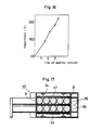
- In this microwave heating there was determined a relation between the heating time (unit: minute) and the temperature of the central portion of the agglomerated preform. The results obtained are as shown in Fig. 11. As can be seen from this graph, there exists a proportional relationship between the heating time and the central portion temperature, and the heating method of the present invention is very stable and superior in controllability.
- Fig. 12 is a sectional side view showing another example of a microwave heating apparatus and Fig. 13 is a plan view thereof. There are provided
quartz pipe passages 35 in five rows transversely and in two stages vertically, that is, a total of ten rows. On an inlet side there are provided ten (five rows in two stages)loading air cylinders 39, and in inlet portions there are providedpreform arranging cylinders 37 in two stages vertically for arranging ten agglomerated preforms B. On an outlet side there are providedlateral discharge cylinders 36 andlongitudinal discharge cylinders 38 each in two stages vertically for discharging the preforms successively. Ten agglomerated preforms which have been fed before the inlet portions by the arrangingcylinders 37 are inserted, ten as one group, into thequartz pipe passages 35 by means of theloading cylinders 39, in which they are heated under the radiation of microwaves introduced through thewaveguides 31. The succeeding preforms are loaded successively by repeating the above operation. The agglomerated preforms B undergoes microwave heating for a predetermined time while they move through the quartz pipe passages, and when a predetermined temperature has been reached, one group of them are discharged together. Then, before the next discharge is performed, they are conveyed in the direction of arrow by a cooperative operation based on time difference of the lateral andlongitudinal cylinders - The following is a detailed description about a heating method utilizing high-frequency heating.
- Referring to Fig. 14, which is an explanatory entire view showing an example of a high-frequency heating apparatus, agglomerated preforms B are carried on a
conveyor belt 45 in the direction of arrow, andelectrode plates - Silicon carbide was incorporated in a composite material consisting of 70 parts by weight polypropylene powder and 30 parts by weight glass fibers in such a manner that the proportion of the silicon carbide was 1.0 wt%. Using the resulting mixture, a columnar preform of 220 mm dia. by 160 mm long was produced and it was then subjected to the radiation of high frequency of 13 MHz x 3 KW. At this time, the temperature of the preform rose to 260°C in only 2 minutes, and the temperature difference distribution in the interior of the preform was ±5°C, thus exhibiting excellent uniformity. The heated preform was then molded by means of a compression molding machine. The mechanical strength of the final product was higher than that of a molded article obtained by using a comparative product which had been subjected to kneading and heating.
- In place of the silicon carbide used in Example No.3, the proportion of carbon black was incorporated in the composite material. Using the resulting mixture, a columnar preform of 220 mm dia. by 160 mm (weight: 2.25 kg) was produced and it was then subjected to a high-frequency heating at 13 MHz x 6 KW. As a result, the temperature of the preform rose to 220°C in 3 minutes and 30 seconds. At this time, the temperature difference distribution in the interior of the preform was ±5°C.
- In this high-frequency heating there was determined a relation between the heating time (unit: minute) and the temperature of the central portion of the agglomerated preform. There were obtained such results as shown in Fig. 16. As can be seen from this graph, there exists a proportional relationship between the heating time and the central portion temperature, and the heating method of the present invention is very stable and superior in controllability.
- Fig. 15 is an explanatory view showing another working concept of the high-frequency heating method. Carbon black was incorporated in a composite material consisting of 65 parts by weight polypropylene and 35 parts by weight glass fibers so that the proportion of the carbon black was 1.0 wt%. Using the resulting mixture, a columnar preform of 320 mm dia. by 210 mm long was produced. The preform was allowed to travel from left to right on a
conveyor belt 45 in Fig. 15 and subjected to a high-frequency heating (13 MHz x 3 KW) using aninfrared heater 46 and then a high frequency generator (betweenelectrode plates 41 and 42), then further subjected to a high-frequency heating using another high frequency generator (betweenelectrode plates 43 and 44) with anupper electrode plate 43 being inclined to enhance the heating efficiency gradually. Lastly, heating was again performed from above using aninfrared heater 46. The preform was heated to 220°C in 3 minutes and the temperature difference distribution in the interior of the preform was ±3°C. Although in the illustratedelectrode plates lower electrode plate 44 may also be inclined in the same manner. By changing the impedance of the passing preform it is made possible to make a more delicate heating control. Even if there is adopted a method wherein each preform is passed through a quartz pipe or the like, there will be exerted no bad influence on the high frequency heating. - Fig. 17 illustrates a high-
frequency heating apparatus 40 corresponding to the apparatus shown in Fig. 12, whereby preforms B arranged in five rows, two stages, are heated successively.Electrode plates quartz pipe passages 35 so as to wholly cover thequartz pipe passages 35. The preforms are heated in thequartz pipe passages 35 for a predetermined time and then taken out successively. - In connection with the
heating apparatus 1 shown in Figs. 1, 4 and 5, there may be adopted a method wherein the preform B is heated from the interior thereof without using thegas nozzles 5. In this case, as the preform B there is used one having such holes B₂ as shown in Fig. 8, or with such holes B₂ being closed at one ends. These holes are formed by inserting heating needles arranged in conformity with the arrangement of the holes into a preform. It is preferable that the temperature of the needles be below the temperature at which the synthetic resin contained in the preform melts and adheres to the needles. - Nine needles heated to about 140°C are pierced into an agglomerated preform obtained by using a composite of polypropylene and glass fibers form holes with one ends being closed. The holding time in the pierced state was about 1 minute. If the needle heating temperature is too high, the resin will be deteriorated and adhere to the needles, resulting in that the maintenance of the needles is troublesome and the operability is deteriorated. Therefore, it is desirable that the needle heating temperature be set in a temperature range in which the resin used does not adhere to the needles, taking the melting temperature of the resin into account. The needles may be held at room temperature, at which temperature, however, the holes may be closed by spring back of the glass fibers. It was found better for the needles to be heated to a certain extent for retaining the holes once formed.
- Next, the preform now having such holes is loaded into the heating apparatus shown in Fig. 4, and nitrogen gas held at 240°C is blown directly (without using gas nozzles) into the holes of the preform for about 2 minutes. The heated nitrogen gas thus entered the holes is dispersed to the interior of the preform and thereafter discharged from the upper portion, whereby the preform is heated to about 200-220°C from the interior.
- This method is advantageous in that the heating can be done uniformly in a short time, and that since
gas nozzles 5 or rod-like heaters 22 are not used there occurs neither adhesion nor clogging of molten resin, and handling is easy. - According to the molding method of the present invention, since it constructed as above, an agglomerated preform containing a synthetic resin and a reinforcing fiber can be heated efficiently in a uniform temperature distribution throughout the whole thereof.
- Further, by selecting form or components of the preform suitable for the heating method used it is made possible to raise the temperature of the preform uniformly and efficiently in a short time according to the said heating method.
- As a result, in the next molding process it is possible to produce a fiber-reinforced composite product of homogeneous properties and high quality.
Claims (13)
- A method for molding a fiber-reinforced composite material comprising a synthetic resin material and reinforcing fibers dispersed therein, which method includes the steps of forming said composite material into an agglomerated preform, heating said preform from the interior thereof, and molding the heated preform into a desired shape.
- A molding method according to claim 1, wherein an optional number of gas nozzle(s) is (are) inserted into said preform and a high temperature gas is blown into the preform through said gas nozzle(s).
- A molding method according to claim 2, wherein said gas nozzle comprises a sharp tip portion and a body portion having an optional number of gas ejection holes, and a high temperature gas is ejected from said gas ejection holes to heat said preform.
- A molding method according to claim 1, wherein an optional number of rod-like heater(s) is (are) inserted into said preform, and the preform is heated by said rod-like heaters.
- A molding method according to claim 1, wherein a dielectric loss improver is incorporated into said composite material, then the resulting mixture is formed into an agglomerated preform, and said preform is subjected to microwave heating.
- A molding method according to claim 5, wherein, as said dielectric loss improver, at least one member selected from the group consisting of silicon carbide, carbon black, rubbery materials, marble, soda glass, water, ethylene glycol, and glycerin, is used in an amount of 0.1 to 4.5 % by weight based on the weight of said composite material.
- A molding method according to claim 1, wherein a dielectric loss improver is incorporated into said composite material, then the resulting mixture is formed into an agglomerated preform, and said preform is subjected to high-frequency heating through electrode plates.
- A molding method according to claim 7, wherein, as said dielectric loss improver, at least one member selected from the group consisting of silicon carbide, carbon black, rubbery materials, marble, soda glass, water, ethylene glycol, and glycerin, is used in an amount of 0.1 to 40% by weight based on the weight of said composite material.
- A molding method according to claim 1, wherein an optional number hole(s) having closed one end(s) is (are) formed in said preform, and a high temperature gas is blown into said hole(s) to heat the preform.
- A molding method according to claim 9, wherein said optional number of hole(s) is (are) formed by inserting heated needle(s) into said preform, said heated needle(s) having been heated to a temperature below a temperature at which the synthetic resin material melts and adheres to the needle(s).
- A preform of a fiber-reinforced composite material comprising a synthetic resin material and reinforcing fibers disposed uniformly therein, said preform being in an agglomerated form having an optional number of holes.
- A preform of a fiber-reinforced composite material, said fiber-reinforced composite material comprising a synthetic resin material and reinforcing fibers dispersed uniformly therein, and with a dielectric loss improver being incorporated in said composite material in an amount of 0.1 to 40 % by weight based on the weight of the composite material.
- A preform according to claim 12, wherein as said dielectric loss improver there is used at least one member selected from the group consisting of silicon carbide, carbon black, rubbery materials, marble, soda glass, water, ethylene glycol, and glycerin.
Applications Claiming Priority (9)
| Application Number | Priority Date | Filing Date | Title |
|---|---|---|---|
| JP32283689A JPH03182307A (en) | 1989-12-12 | 1989-12-12 | Preform of fiber reinforced composite material |
| JP32283789A JPH03182308A (en) | 1989-12-12 | 1989-12-12 | Heating of fiber reinforced composite material |
| JP322836/89 | 1989-12-12 | ||
| JP322837/89 | 1989-12-12 | ||
| JP32283989A JPH03182310A (en) | 1989-12-12 | 1989-12-12 | Heating of fiber reinforced composite material |
| JP322838/89 | 1989-12-12 | ||
| JP322839/89 | 1989-12-12 | ||
| JP32283889A JPH03182309A (en) | 1989-12-12 | 1989-12-12 | Heating of fiber reinforced composite material |
| PCT/JP1990/001628 WO1991008883A1 (en) | 1989-12-12 | 1990-12-12 | Method of molding fiber-reinforced composite material and premolded body of said material |
Publications (3)
| Publication Number | Publication Date |
|---|---|
| EP0457917A1 true EP0457917A1 (en) | 1991-11-27 |
| EP0457917A4 EP0457917A4 (en) | 1992-06-03 |
| EP0457917B1 EP0457917B1 (en) | 1995-08-02 |
Family
ID=27480288
Family Applications (1)
| Application Number | Title | Priority Date | Filing Date |
|---|---|---|---|
| EP91900325A Expired - Lifetime EP0457917B1 (en) | 1989-12-12 | 1990-12-12 | Method of molding a premolded body of fiber-reinforced composite material |
Country Status (4)
| Country | Link |
|---|---|
| US (1) | US5283026A (en) |
| EP (1) | EP0457917B1 (en) |
| DE (1) | DE69021377T2 (en) |
| WO (1) | WO1991008883A1 (en) |
Cited By (2)
| Publication number | Priority date | Publication date | Assignee | Title |
|---|---|---|---|---|
| FR2688439A1 (en) * | 1992-03-11 | 1993-09-17 | Kobe Steel Ltd | Method and device for heating and extruding a solid preform (blank) |
| CN103057013A (en) * | 2013-01-09 | 2013-04-24 | 南京航空航天大学 | Fiber reinforced resin matrix composite material heat curing device and method thereof |
Families Citing this family (20)
| Publication number | Priority date | Publication date | Assignee | Title |
|---|---|---|---|---|
| AU668470B2 (en) * | 1993-07-12 | 1996-05-02 | Seaward International, Inc. | Elongated structural member and method and apparatus for making same |
| US5697421A (en) * | 1993-09-23 | 1997-12-16 | University Of Cincinnati | Infrared pressureless infiltration of composites |
| US5591784A (en) * | 1994-06-17 | 1997-01-07 | Three Bond Co., Ltd. | Curing of fiber-reinforced composite structures |
| DE19718505A1 (en) * | 1997-05-02 | 1998-11-05 | Huels Chemische Werke Ag | Process for thermoforming pipes using an HF field |
| US6682619B2 (en) | 2001-07-17 | 2004-01-27 | Sikorsky Aircraft Corporation | Composite pre-preg ply having tailored dielectrical properties and method of fabrication thereof |
| DE10217391A1 (en) * | 2002-04-18 | 2003-11-13 | Siemens Ag | Stackable crate has lip around top edge of its walls which grips base of crate above and is made from fire-retardant duroplast |
| JP5558812B2 (en) * | 2006-05-31 | 2014-07-23 | ダウ グローバル テクノロジーズ エルエルシー | Additives for using microwave energy to selectively heat thermoplastic polymer systems |
| AT506068B1 (en) * | 2008-03-12 | 2009-06-15 | Franz Stransky Ges M B H | TOOL FOR THE MANUFACTURE OF PLASTICS |
| WO2010122469A1 (en) * | 2009-04-21 | 2010-10-28 | Koninklijke Philips Electronics N.V. | Heating system and method of heating a body of a preform |
| US8623263B2 (en) * | 2009-08-05 | 2014-01-07 | Ocv Intellectual Capital, Llc | Process for curing a porous muffler preform |
| US20110031660A1 (en) * | 2009-08-05 | 2011-02-10 | Huff Norman T | Method of forming a muffler preform |
| US10005246B2 (en) * | 2013-08-22 | 2018-06-26 | Faurecia Interior Systems, Inc. | Methods for making interior panels for motor vehicles |
| GB2535193A (en) | 2015-02-12 | 2016-08-17 | Zodiac Seats Uk Ltd | Tool for curing a composite component |
| US10071521B2 (en) * | 2015-12-22 | 2018-09-11 | Mks Instruments, Inc. | Method and apparatus for processing dielectric materials using microwave energy |
| US11007674B2 (en) * | 2015-12-25 | 2021-05-18 | Teijin Limited | Method for manufacturing heated molding material and device for heating molding material |
| JP6604322B2 (en) * | 2016-12-28 | 2019-11-13 | トヨタ自動車株式会社 | Method for producing fiber-reinforced resin molded body |
| WO2019118702A2 (en) * | 2017-12-13 | 2019-06-20 | Kent Byron | Method of forming polypropylene bottles |
| LU100718B1 (en) * | 2018-03-01 | 2019-10-01 | Cristalux Int Sarl | THERMOPLASTIC MATTRESS MATERIAL, PROCESS FOR MANUFACTURING THE SAME, AND USES THEREOF |
| DE102018110238A1 (en) * | 2018-04-27 | 2019-10-31 | Fox Velution Gmbh | Tool for processing plastic particle material for producing a particle foam component |
| US11639304B2 (en) | 2020-02-07 | 2023-05-02 | Raytheon Technologies Corporation | Method of fabricating a glass-ceramic matrix composite |
Citations (2)
| Publication number | Priority date | Publication date | Assignee | Title |
|---|---|---|---|---|
| WO1986006393A1 (en) * | 1985-04-22 | 1986-11-06 | The Dow Chemical Company | Method and apparatus for the preparation of foamed thermoplastic articles |
| EP0278363A2 (en) * | 1987-02-10 | 1988-08-17 | Menzolit GmbH | Method and apparatus for preparing fibre-reinforced thermoplastic material for the manufacture of moulded articles |
Family Cites Families (41)
| Publication number | Priority date | Publication date | Assignee | Title |
|---|---|---|---|---|
| CA703789A (en) * | 1965-02-16 | Dietzsch Hans-Joachim | Producing material of honeycomb structure | |
| US598282A (en) * | 1898-02-01 | Clay-steamer | ||
| US2289177A (en) * | 1939-02-09 | 1942-07-07 | Perfotex Company | Composite foraminous material |
| US2244550A (en) * | 1940-03-11 | 1941-06-03 | Chandler Frank Jermain | Perforating method and apparatus |
| BE488915A (en) * | 1948-05-08 | |||
| US2533609A (en) * | 1949-03-19 | 1950-12-12 | Bell Aircraft Corp | Process for manufacturing minutely orificed articles |
| US2707804A (en) * | 1951-04-28 | 1955-05-10 | Us Rubber Co | Apparatus for steam curing frothed latex |
| US2900109A (en) * | 1957-04-29 | 1959-08-18 | Fibreboard Paper Products Corp | Method for preheating cementitious insulating material |
| US3005491A (en) * | 1958-10-08 | 1961-10-24 | Diamond National Corp | Chamberless mold and process of making same |
| NL265964A (en) * | 1962-09-28 | |||
| US3391846A (en) * | 1963-08-08 | 1968-07-09 | Du Pont | Heating with antiferromagnetic particles in a high frequency magnetic field |
| US3405204A (en) * | 1964-07-23 | 1968-10-08 | Du Pont | Process of vulcanizing with ammonia a chlorosulfonated polyethylene coating containing an active metal oxide |
| US3477961A (en) * | 1966-03-09 | 1969-11-11 | Chevron Res | Poly-alpha-olefin iron-nickel alloy mixtures |
| DE1784801A1 (en) * | 1968-09-20 | 1971-12-02 | Astik Werk Guenther Jaehne Bsb | Process and device for the production of perforated or with slots or other openings provided fiber-reinforced plates or molded bodies of high strength |
| US3650866A (en) * | 1969-10-09 | 1972-03-21 | Exxon Research Engineering Co | Increasing strip tensile strength of melt blown nonwoven polypropylene mats of high tear resistance |
| US3704194A (en) * | 1970-07-02 | 1972-11-28 | Gen Electric | Perforated reinforced plastic member and method for making |
| US3719736A (en) * | 1970-10-08 | 1973-03-06 | Gen Foods Corp | Method of producing perforated plastic film |
| US3787546A (en) * | 1970-12-21 | 1974-01-22 | Gen Electric | Method for making a perforated plastic article |
| US3952402A (en) * | 1971-02-02 | 1976-04-27 | Mero Ag | Composite structural panel and process of making |
| US3919369A (en) * | 1971-03-08 | 1975-11-11 | American Filtrona Corp | Method of manufacturing a self-contained low pressure drop filter |
| US3763293A (en) * | 1971-06-09 | 1973-10-02 | Bischoff Chemical Corp | Process of molding giant articles of structured plastic |
| US3849527A (en) * | 1971-06-29 | 1974-11-19 | Drostholm F H | Method for making reinforced or filled resin products |
| US3850723A (en) * | 1971-09-20 | 1974-11-26 | Ppg Industries Inc | Method of making a stampable reinforced sheet |
| US4218276A (en) * | 1972-03-31 | 1980-08-19 | Avco Corporation | Method for making 3-D structures |
| US4251477A (en) * | 1977-10-03 | 1981-02-17 | Plymouth Locomotive Works, Inc. | On-line fluid injecting method |
| US4132519A (en) * | 1977-10-28 | 1979-01-02 | Rohr Industries, Inc. | Controlled porosity of uncured reinforced thermo-setting plastic material |
| FR2433003A1 (en) * | 1978-08-08 | 1980-03-07 | Commissariat Energie Atomique | METHOD FOR MANUFACTURING A MATERIAL REINFORCED WITH A THREE-DIMENSIONAL TEXTILE STRUCTURE |
| FR2467092A1 (en) * | 1979-10-11 | 1981-04-17 | Hutchinson Mapa | IMPROVEMENTS IN PROCESSES FOR THE MANUFACTURE OF INDEPENDENT TYPE ROOMS FOR VEHICLE WHEELS AND THE LIKE, AND INCREASABLE CHAMBERS THUS OBTAINED |
| JPS59118418A (en) * | 1982-12-24 | 1984-07-09 | Toshiba Corp | Resin molding device |
| JPS59220932A (en) * | 1983-05-31 | 1984-12-12 | Toshiba Corp | Preheater of molding resin for semiconductor element |
| US4545837A (en) * | 1983-05-31 | 1985-10-08 | United Technologies Corporation | Molded-in composite bushings |
| US4696711A (en) * | 1983-09-30 | 1987-09-29 | Mcdonnell Douglas Corporation | Method for forming holes in composites |
| US4486372A (en) * | 1983-09-30 | 1984-12-04 | Rohr Industries, Inc. | Method for fabricating contoured perforated composite laminate structure |
| US4652415A (en) * | 1985-02-11 | 1987-03-24 | General Motors Corporation | Method of manufacture of a molded friction pad |
| US4767799A (en) * | 1985-03-04 | 1988-08-30 | Phillips Petroleum Company | Radio frequency energy sensitized compositions and method for sensitizing compositions to radio frequency energy |
| DE3673336D1 (en) * | 1985-10-16 | 1990-09-13 | Toyota Motor Co Ltd | METHOD FOR PRODUCING A WOODEN MOLDED BODY. |
| JPS62242507A (en) * | 1986-04-16 | 1987-10-23 | Kuraudo:Kk | Waste plastic heat treatment method |
| US4950532A (en) * | 1986-10-30 | 1990-08-21 | Azdel, Inc. | Process for producing glass fiber reinforced thermoplastic compression molded materials and said molded materials |
| US5047198A (en) * | 1988-03-30 | 1991-09-10 | General Electric Company | Compression molding of composite parts on hot mold surfaces with a short cycle time |
| US4980384A (en) * | 1988-09-05 | 1990-12-25 | Shin-Etsu Chemical Co., Ltd. | Foamable silicone rubber composition and method for curing the same |
| US5066442A (en) * | 1989-02-28 | 1991-11-19 | Massachusetts Institute Of Technology | Method of producing a composite article |
-
1990
- 1990-12-12 EP EP91900325A patent/EP0457917B1/en not_active Expired - Lifetime
- 1990-12-12 WO PCT/JP1990/001628 patent/WO1991008883A1/en active IP Right Grant
- 1990-12-12 DE DE69021377T patent/DE69021377T2/en not_active Expired - Fee Related
- 1990-12-12 US US07/741,515 patent/US5283026A/en not_active Expired - Fee Related
Patent Citations (2)
| Publication number | Priority date | Publication date | Assignee | Title |
|---|---|---|---|---|
| WO1986006393A1 (en) * | 1985-04-22 | 1986-11-06 | The Dow Chemical Company | Method and apparatus for the preparation of foamed thermoplastic articles |
| EP0278363A2 (en) * | 1987-02-10 | 1988-08-17 | Menzolit GmbH | Method and apparatus for preparing fibre-reinforced thermoplastic material for the manufacture of moulded articles |
Non-Patent Citations (1)
| Title |
|---|
| See also references of WO9108883A1 * |
Cited By (3)
| Publication number | Priority date | Publication date | Assignee | Title |
|---|---|---|---|---|
| FR2688439A1 (en) * | 1992-03-11 | 1993-09-17 | Kobe Steel Ltd | Method and device for heating and extruding a solid preform (blank) |
| CN103057013A (en) * | 2013-01-09 | 2013-04-24 | 南京航空航天大学 | Fiber reinforced resin matrix composite material heat curing device and method thereof |
| CN103057013B (en) * | 2013-01-09 | 2015-07-29 | 南京航空航天大学 | A kind of device and method that is heating and curing of fiber-reinforced resin matrix compound material |
Also Published As
| Publication number | Publication date |
|---|---|
| EP0457917B1 (en) | 1995-08-02 |
| US5283026A (en) | 1994-02-01 |
| DE69021377D1 (en) | 1995-09-07 |
| EP0457917A4 (en) | 1992-06-03 |
| DE69021377T2 (en) | 1996-01-25 |
| WO1991008883A1 (en) | 1991-06-27 |
Similar Documents
| Publication | Publication Date | Title |
|---|---|---|
| US5283026A (en) | Method for molding fiber-reinforced composite material | |
| KR930000742B1 (en) | Pultrusion process | |
| US4812283A (en) | Method of manufacture of formed article | |
| US3832429A (en) | Method and apparatus for the production of sheet on block of agglomerated granules of polystryrene | |
| US7122146B2 (en) | Injection molding of polymers by microwave heating | |
| US5482665A (en) | Method/apparatus for making fiber-filled cushion | |
| EP0334851B1 (en) | Method of manufacturing molded articles | |
| US4460530A (en) | Method for producing porous shaped products | |
| EP0830471A1 (en) | Method of forming a thermoactive binder composite | |
| KR20020081404A (en) | Woody formed article and method for producing the same | |
| US5908596A (en) | Process and apparatus for expanding and molding fiberglass laminate and the panel formed thereby | |
| KR100632164B1 (en) | Method for producing a fiber-reinforced thermoplastic molded article and molded article produced by the method | |
| US3992501A (en) | Process for the manufacture of void-free polyolefin foam moldings | |
| EP0019149B1 (en) | Molding process and apparatus therefor | |
| US11584044B2 (en) | Methods of forming near-net fiber reinforced thermoplastic composite components | |
| JPH11188749A (en) | Method and apparatus for producing molded product | |
| EP0743165B1 (en) | Method and apparatus for moulding reinforced thermoplastics | |
| US5685956A (en) | Method and apparatus for binding fibers in a fiber reinforced preform | |
| JPH04153008A (en) | Heating method for fiber reinforced composite material | |
| JPH03182308A (en) | Heating of fiber reinforced composite material | |
| JPH03182309A (en) | Heating of fiber reinforced composite material | |
| JPH06102335B2 (en) | Method for heating fiber-reinforced composite material preform | |
| JPS5698124A (en) | Method and apparatus for blow molding of sheet material | |
| EP0408898A2 (en) | Method of manufacturing fibrereinforced laminates of thermoplastic synthetic resin, as well as products obtained by using the method | |
| JPH0857953A (en) | Extrusion molding machine |
Legal Events
| Date | Code | Title | Description |
|---|---|---|---|
| PUAI | Public reference made under article 153(3) epc to a published international application that has entered the european phase |
Free format text: ORIGINAL CODE: 0009012 |
|
| 17P | Request for examination filed |
Effective date: 19910911 |
|
| AK | Designated contracting states |
Kind code of ref document: A1 Designated state(s): DE FR GB |
|
| A4 | Supplementary search report drawn up and despatched |
Effective date: 19920413 |
|
| AK | Designated contracting states |
Kind code of ref document: A4 Designated state(s): DE FR GB |
|
| 17Q | First examination report despatched |
Effective date: 19931015 |
|
| GRAA | (expected) grant |
Free format text: ORIGINAL CODE: 0009210 |
|
| AK | Designated contracting states |
Kind code of ref document: B1 Designated state(s): DE FR GB |
|
| ET | Fr: translation filed | ||
| REF | Corresponds to: |
Ref document number: 69021377 Country of ref document: DE Date of ref document: 19950907 |
|
| PLBE | No opposition filed within time limit |
Free format text: ORIGINAL CODE: 0009261 |
|
| STAA | Information on the status of an ep patent application or granted ep patent |
Free format text: STATUS: NO OPPOSITION FILED WITHIN TIME LIMIT |
|
| 26N | No opposition filed | ||
| PGFP | Annual fee paid to national office [announced via postgrant information from national office to epo] |
Ref country code: GB Payment date: 19971203 Year of fee payment: 8 |
|
| PGFP | Annual fee paid to national office [announced via postgrant information from national office to epo] |
Ref country code: FR Payment date: 19971209 Year of fee payment: 8 |
|
| PG25 | Lapsed in a contracting state [announced via postgrant information from national office to epo] |
Ref country code: GB Free format text: LAPSE BECAUSE OF NON-PAYMENT OF DUE FEES Effective date: 19981212 |
|
| PGFP | Annual fee paid to national office [announced via postgrant information from national office to epo] |
Ref country code: DE Payment date: 19981221 Year of fee payment: 9 |
|
| GBPC | Gb: european patent ceased through non-payment of renewal fee |
Effective date: 19981212 |
|
| PG25 | Lapsed in a contracting state [announced via postgrant information from national office to epo] |
Ref country code: FR Free format text: LAPSE BECAUSE OF NON-PAYMENT OF DUE FEES Effective date: 19990831 |
|
| REG | Reference to a national code |
Ref country code: FR Ref legal event code: ST |
|
| PG25 | Lapsed in a contracting state [announced via postgrant information from national office to epo] |
Ref country code: DE Free format text: LAPSE BECAUSE OF NON-PAYMENT OF DUE FEES Effective date: 20001003 |