EP0457734B1 - A method of detecting the maximum temperature to which a mechanical part made of ferromagnetic material has been subjected - Google Patents
A method of detecting the maximum temperature to which a mechanical part made of ferromagnetic material has been subjected Download PDFInfo
- Publication number
- EP0457734B1 EP0457734B1 EP91830145A EP91830145A EP0457734B1 EP 0457734 B1 EP0457734 B1 EP 0457734B1 EP 91830145 A EP91830145 A EP 91830145A EP 91830145 A EP91830145 A EP 91830145A EP 0457734 B1 EP0457734 B1 EP 0457734B1
- Authority
- EP
- European Patent Office
- Prior art keywords
- mechanical part
- detecting
- subjected
- sensor
- maximum temperature
- Prior art date
- Legal status (The legal status is an assumption and is not a legal conclusion. Google has not performed a legal analysis and makes no representation as to the accuracy of the status listed.)
- Expired - Lifetime
Links
- 238000000034 method Methods 0.000 title claims description 12
- 239000003302 ferromagnetic material Substances 0.000 title claims description 6
- 230000005291 magnetic effect Effects 0.000 claims description 10
- 238000011088 calibration curve Methods 0.000 claims description 3
- 238000011282 treatment Methods 0.000 claims description 3
- 230000005355 Hall effect Effects 0.000 claims description 2
- 230000005415 magnetization Effects 0.000 claims 1
- 229910001018 Cast iron Inorganic materials 0.000 description 4
- 239000000463 material Substances 0.000 description 3
- XEEYBQQBJWHFJM-UHFFFAOYSA-N iron Substances [Fe] XEEYBQQBJWHFJM-UHFFFAOYSA-N 0.000 description 2
- 238000010276 construction Methods 0.000 description 1
- 230000005294 ferromagnetic effect Effects 0.000 description 1
- 238000010438 heat treatment Methods 0.000 description 1
- 229910052742 iron Inorganic materials 0.000 description 1
- 238000005259 measurement Methods 0.000 description 1
- 238000012544 monitoring process Methods 0.000 description 1
- 229920003023 plastic Polymers 0.000 description 1
- 239000004033 plastic Substances 0.000 description 1
Images


Classifications
-
- G—PHYSICS
- G01—MEASURING; TESTING
- G01K—MEASURING TEMPERATURE; MEASURING QUANTITY OF HEAT; THERMALLY-SENSITIVE ELEMENTS NOT OTHERWISE PROVIDED FOR
- G01K7/00—Measuring temperature based on the use of electric or magnetic elements directly sensitive to heat ; Power supply therefor, e.g. using thermoelectric elements
- G01K7/36—Measuring temperature based on the use of electric or magnetic elements directly sensitive to heat ; Power supply therefor, e.g. using thermoelectric elements using magnetic elements, e.g. magnets, coils
Definitions
- the present invention relates to a method of detecting the maximum temperature to which a mechanical part made of ferromagnetic material has been subjected.
- the object of the present invention is to provide a method of the type indicated above which is easy to carry out and accurate over a wide temperature range.
- the subject of the present invention is a method of the type indicated above, characterised in that it comprises the steps of:
- the magnitude of the signal detected depends on the maximum temperature to which the part has been brought beforehand and is unaffected by the time which has elapsed before and after that moment.
- Figure 1 shows a magnetic field sensor 6 for example a linear Hall-effect sensor, such as the LOHET II SS94A1 produced by Microswitch of the Honeywell Group.
- the sensor 6 is connected to a device 8 for amplifying and displaying the signals emitted, in known manner not described further.
- a generic component (e.g. a flywheel) 2 of ferromagnetic material, for example of cast iron, is mounted in known manner for rotation about its own central axis 4 so that its periphery is at a distance of no more than 1.5 mm from the sensor 6 .
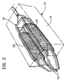
- a surface portion 10 of the part 2 has been magnetised permanently beforehand, for example by an electromagnet 12 shown in Figure 2.
- This is constituted by a casing 14 of plastics material from which project the converging ends 16 of a substantially U-shaped core 18 of laminated ferromagnetic material (for example, soft sheet-iron).
- Coils 20 are wound on the main arms of the core 18 and connected to an electrical supply circuit, not shown.
- the ends 16 of the core 18 are brought into contact with the portion 10 of the part 2 and current is passed through the coils 20 so that the surface portion 10 of the part 2 is permanently magnetised.
- the part 2 may be subjected to mechanical operations (not at the point marked) and to treatments which cause its temperature to rise and of which it is necessary to know the maximum value.
- the magnetised portion 10 of the surface of the part 2 When the magnetised portion 10 of the surface of the part 2 is subsequently brought to a given distance from the sensor 6 , the latter emits a signal whose value, expressed in volts as shown in Figure 3, depends on the maximum temperature to which the part has been subjected and is unaffected by the time which has elapsed since that moment or since any other heat treatments undergone.
Landscapes
- Physics & Mathematics (AREA)
- General Physics & Mathematics (AREA)
- Measuring Magnetic Variables (AREA)
- Measuring Temperature Or Quantity Of Heat (AREA)
Description
- Several methods of monitoring the actual temperature of a ferromagnetic part are known in the field (EP-A-11862 and DE-A-2654837).
- The present invention relates to a method of detecting the maximum temperature to which a mechanical part made of ferromagnetic material has been subjected.
- The object of the present invention is to provide a method of the type indicated above which is easy to carry out and accurate over a wide temperature range.
- The subject of the present invention is a method of the type indicated above, characterised in that it comprises the steps of:
- permanently magnetising at least a portion of the mechanical part which may then be subjected to operations, treatments and/or working (not at the point marked) which involve a temperature rise,
- detecting the signal emitted by a magnetic field sensor located at a given distance from the magnetic mark, and
- comparing the value of the signal with a calibration curve obtained from similar signals detected at the same distance from magnetic marks on parts which have been brought to different (maximum) temperatures beforehand and thus deriving the desired value of the maximum temperature reached by the mechanical part.
- It has in fact been discovered that the magnitude of the signal detected depends on the maximum temperature to which the part has been brought beforehand and is unaffected by the time which has elapsed before and after that moment.
- Advantages and characteristics of the present invention will become clear from the detailed description which follows, with reference to the appended drawings, provided purely by way of non-limiting example, in which:
- Figure 1 is a schematic view of a device for carrying out the method of the invention,
- Figure 2 is a perspective view of an electromagnet used in carrying out the method of the invention, and
- Figure 3 is a graph showing the temperature dependence of the signal emitted by a sensor used in the method of the invention.
- Figure 1 shows a magnetic field sensor 6 for example a linear Hall-effect sensor, such as the LOHET II SS94A1 produced by Microswitch of the Honeywell Group. The sensor 6 is connected to a device 8 for amplifying and displaying the signals emitted, in known manner not described further. A generic component (e.g. a flywheel) 2 of ferromagnetic material, for example of cast iron, is mounted in known manner for rotation about its own central axis 4 so that its periphery is at a distance of no more than 1.5 mm from the sensor 6 .
- A
surface portion 10 of thepart 2 has been magnetised permanently beforehand, for example by anelectromagnet 12 shown in Figure 2. This is constituted by acasing 14 of plastics material from which project theconverging ends 16 of a substantially U-shapedcore 18 of laminated ferromagnetic material (for example, soft sheet-iron). -
Coils 20 are wound on the main arms of thecore 18 and connected to an electrical supply circuit, not shown. Theends 16 of thecore 18 are brought into contact with theportion 10 of thepart 2 and current is passed through thecoils 20 so that thesurface portion 10 of thepart 2 is permanently magnetised. - After this magnetic marking step, the
part 2 may be subjected to mechanical operations (not at the point marked) and to treatments which cause its temperature to rise and of which it is necessary to know the maximum value. - When the
magnetised portion 10 of the surface of thepart 2 is subsequently brought to a given distance from the sensor 6 , the latter emits a signal whose value, expressed in volts as shown in Figure 3, depends on the maximum temperature to which the part has been subjected and is unaffected by the time which has elapsed since that moment or since any other heat treatments undergone. - It suffices, therefore, to compare the signal obtained with a calibration curve formed from signals emitted by the sensor when it is located at the same distance from magnetic marks on parts which have been brought to different maximum temperatures beforehand in order to derive the value of the maximum temperature to which the
flywheel 2 has been subjected. - For a material such as cast iron, it has been found experimentally that signals of appreciable strength are obtained up to maximum temperatures of the order of approximately 180°. If measurements relating to higher temperatures are to be made, it is necessary to apply one or more plates of other suitable ferromagnetic materials to the cast iron part.
- Once magnetised and tested by a magnetic field sensor, these materials give significant signals even after they have been brought to temperatures higher than that referred to in the case of cast iron.
- Naturally, the principle of the invention remaining the same, the details of construction and forms of embodiment may be varied widely with respect to those described and illustrated purely by way of example, without thereby departing from its scope as defined in the claims.
Claims (4)
- A method of detecting the maximum temperature to which a mechanical part (2) made of ferromagnetic material has been subjected, characterised in that it comprises the steps of:
magnetising at least a portion (10) of the mechanical part (2) to provide a residual magnetization; the mechanical part (2) except at the magnetized portion (10) may then be subjected to operations, treatments and/or working which involve a temperature rise,
subsequently detecting the signal emitted by a magnetic field sensor (6) located at a given distance from the magnetic mark (10), and
comparing the value of the signal with a calibration curve obtained from similar signals detected at the same distance from magnetic marks on parts which have been brought to different maximum temperatures beforehand and thus deriving the desired value of the maximum temperature reached by the mechanical part between the magnetising and the detecting. - A method according to Claim 1, characterised in that the portion (10) of the part (2) is magnetised by an electromagnet (12) which is brought close to the portion (10).
- A method according to any one of the preceding claims, characterised in that the sensor (6) is a Hall-effect sensor.
- A method according to any one of the preceding claims, characterised in that the sensor (6) is kept at a distance of no more than 1.5 mm from the surface of the part (2).
Applications Claiming Priority (2)
| Application Number | Priority Date | Filing Date | Title |
|---|---|---|---|
| IT6732190 | 1990-04-30 | ||
| IT67321A IT1240370B (en) | 1990-04-30 | 1990-04-30 | PROCEDURE FOR THE DETECTION OF THE MAXIMUM TEMPERATURE TO WHICH A MECHANICAL PIECE OF FERROMAGNETIC MATERIAL HAS BEEN SUBJECTED |
Publications (2)
| Publication Number | Publication Date |
|---|---|
| EP0457734A1 EP0457734A1 (en) | 1991-11-21 |
| EP0457734B1 true EP0457734B1 (en) | 1994-10-12 |
Family
ID=11301435
Family Applications (1)
| Application Number | Title | Priority Date | Filing Date |
|---|---|---|---|
| EP91830145A Expired - Lifetime EP0457734B1 (en) | 1990-04-30 | 1991-04-16 | A method of detecting the maximum temperature to which a mechanical part made of ferromagnetic material has been subjected |
Country Status (3)
| Country | Link |
|---|---|
| EP (1) | EP0457734B1 (en) |
| DE (1) | DE69104548T2 (en) |
| IT (1) | IT1240370B (en) |
Families Citing this family (2)
| Publication number | Priority date | Publication date | Assignee | Title |
|---|---|---|---|---|
| DE19616258C2 (en) * | 1996-04-24 | 2000-04-20 | Wolfgang Wuttke | Method and device for monitoring the thermal state of a moving body |
| DE102020100798A1 (en) * | 2020-01-15 | 2021-07-15 | Noris Automation Gmbh | Arrangement for non-contact magnetic temperature measurement on a moving or temporarily non-moving or fixed machine component, method for calibrating such an arrangement and method for performing non-contact magnetic temperature measurement on a moving, temporarily non-moving or fixed machine component |
Family Cites Families (5)
| Publication number | Priority date | Publication date | Assignee | Title |
|---|---|---|---|---|
| FR2109135A5 (en) * | 1970-10-02 | 1972-05-26 | Unelec | |
| DE2654837C3 (en) * | 1976-12-03 | 1979-11-08 | Maschinenfabrik Augsburg-Nuernberg Ag, 8500 Nuernberg | Device for determining the heat transfer coefficient during the heat exchange between steam and turbine rotor during the start-up process of the turbine |
| DE2658203A1 (en) * | 1976-12-22 | 1978-07-06 | Eickhoff Geb | Contactless temp. monitoring device - has ferromagnetic insert and magnet on rotating part with pulse generator in its immediate neighbourhood |
| EP0011862A1 (en) * | 1978-12-04 | 1980-06-11 | General Electric Company | Fuser apparatus having a non-contact temperature sensor |
| DE8626090U1 (en) * | 1986-09-30 | 1986-11-27 | N Proizv Ob Selskokhoz Mashstr |
-
1990
- 1990-04-30 IT IT67321A patent/IT1240370B/en active IP Right Grant
-
1991
- 1991-04-16 DE DE69104548T patent/DE69104548T2/en not_active Expired - Fee Related
- 1991-04-16 EP EP91830145A patent/EP0457734B1/en not_active Expired - Lifetime
Also Published As
| Publication number | Publication date |
|---|---|
| IT9067321A1 (en) | 1991-10-30 |
| IT9067321A0 (en) | 1990-04-30 |
| EP0457734A1 (en) | 1991-11-21 |
| IT1240370B (en) | 1993-12-10 |
| DE69104548T2 (en) | 1995-02-16 |
| DE69104548D1 (en) | 1994-11-17 |
Similar Documents
| Publication | Publication Date | Title |
|---|---|---|
| US3861206A (en) | Method and device for measuring a stress employing magnetostriction | |
| US4805466A (en) | Device for the contactless indirect electrical measurement of the torque at a shaft | |
| US5283130A (en) | Thermomagnetically patterned magnets and method of making same | |
| US4394193A (en) | Method and device for the continuous, contactless monitoring of the structure state of cold strip | |
| CA1095142A (en) | Continuous testing apparatus for determining the magne tic characteristics of a strip of moving material incl uding a method of obtaining a profile indicative of th e quality of the coil throughout the entire length, an d flux inducing and pick-up device therefor | |
| EP0457734B1 (en) | A method of detecting the maximum temperature to which a mechanical part made of ferromagnetic material has been subjected | |
| JP2004222387A (en) | Permanent magnet temperature sensor, permanent magnet motor, and drive system thereof | |
| GB2278450A (en) | Stress measurement in ferromagnetic articles | |
| JPH075051A (en) | Temperature measuring device | |
| EP0456615B1 (en) | A method of detecting the position of a mechanical part made of ferromagnetic material | |
| JP4192333B2 (en) | Method for measuring transformation layer thickness of steel | |
| JPS5753604A (en) | Thickness gauge | |
| KR101419263B1 (en) | Remote temperature sensing device and related remote temperature sensing method | |
| KR100215364B1 (en) | Fault detecting tester for amateur | |
| GB1562444A (en) | Method of calibrating magnetic layerthickness gauges | |
| JPH0783863A (en) | Detection method for axis direction facilitating magnetization | |
| US2236287A (en) | Method of and apparatus for measuring surges | |
| JP2011518331A5 (en) | ||
| Billan | Coercimeter for non-destructive measurement of the coercivity of steel sheets | |
| JPH04168384A (en) | Measurement of magnetic characteristic of superconductive body | |
| Tompkins et al. | New magnetic core loss comparator | |
| SU769647A1 (en) | Method of process inspection of sintered ferrite blanks for magnetic properties | |
| KR20240072901A (en) | An apparatus for measureing curie temperature of magnetic material | |
| AU2333592A (en) | Method and device for measuring the distance between two mutually opposing surfaces by means of the reluctance method | |
| RU2051381C1 (en) | Process of quality inspection of ferromagnetic articles |
Legal Events
| Date | Code | Title | Description |
|---|---|---|---|
| PUAI | Public reference made under article 153(3) epc to a published international application that has entered the european phase |
Free format text: ORIGINAL CODE: 0009012 |
|
| AK | Designated contracting states |
Kind code of ref document: A1 Designated state(s): DE FR GB |
|
| 17P | Request for examination filed |
Effective date: 19911130 |
|
| 17Q | First examination report despatched |
Effective date: 19931227 |
|
| GRAA | (expected) grant |
Free format text: ORIGINAL CODE: 0009210 |
|
| AK | Designated contracting states |
Kind code of ref document: B1 Designated state(s): DE FR GB |
|
| REF | Corresponds to: |
Ref document number: 69104548 Country of ref document: DE Date of ref document: 19941117 |
|
| ET | Fr: translation filed | ||
| PLBE | No opposition filed within time limit |
Free format text: ORIGINAL CODE: 0009261 |
|
| STAA | Information on the status of an ep patent application or granted ep patent |
Free format text: STATUS: NO OPPOSITION FILED WITHIN TIME LIMIT |
|
| 26N | No opposition filed | ||
| PGFP | Annual fee paid to national office [announced via postgrant information from national office to epo] |
Ref country code: GB Payment date: 19960319 Year of fee payment: 6 |
|
| PG25 | Lapsed in a contracting state [announced via postgrant information from national office to epo] |
Ref country code: GB Effective date: 19970416 |
|
| GBPC | Gb: european patent ceased through non-payment of renewal fee |
Effective date: 19970416 |
|
| PGFP | Annual fee paid to national office [announced via postgrant information from national office to epo] |
Ref country code: DE Payment date: 19980325 Year of fee payment: 8 |
|
| PGFP | Annual fee paid to national office [announced via postgrant information from national office to epo] |
Ref country code: FR Payment date: 19980430 Year of fee payment: 8 |
|
| PG25 | Lapsed in a contracting state [announced via postgrant information from national office to epo] |
Ref country code: FR Free format text: LAPSE BECAUSE OF NON-PAYMENT OF DUE FEES Effective date: 19991231 |
|
| REG | Reference to a national code |
Ref country code: FR Ref legal event code: ST |
|
| PG25 | Lapsed in a contracting state [announced via postgrant information from national office to epo] |
Ref country code: DE Free format text: LAPSE BECAUSE OF NON-PAYMENT OF DUE FEES Effective date: 20000201 |