EP0457710A2 - An unmanned flight vehicle including counter rotating rotors positioned within a toroidal shroud and operable to provide all required vehicle flight controls - Google Patents
An unmanned flight vehicle including counter rotating rotors positioned within a toroidal shroud and operable to provide all required vehicle flight controls Download PDFInfo
- Publication number
- EP0457710A2 EP0457710A2 EP91630027A EP91630027A EP0457710A2 EP 0457710 A2 EP0457710 A2 EP 0457710A2 EP 91630027 A EP91630027 A EP 91630027A EP 91630027 A EP91630027 A EP 91630027A EP 0457710 A2 EP0457710 A2 EP 0457710A2
- Authority
- EP
- European Patent Office
- Prior art keywords
- fuselage
- rotors
- rotor
- flight
- pitch
- Prior art date
- Legal status (The legal status is an assumption and is not a legal conclusion. Google has not performed a legal analysis and makes no representation as to the accuracy of the status listed.)
- Granted
Links
- 125000004122 cyclic group Chemical group 0.000 claims description 42
- 230000000694 effects Effects 0.000 claims description 13
- 230000007246 mechanism Effects 0.000 claims description 6
- 239000002131 composite material Substances 0.000 claims description 5
- 230000008878 coupling Effects 0.000 claims description 3
- 238000010168 coupling process Methods 0.000 claims description 3
- 238000005859 coupling reaction Methods 0.000 claims description 3
- 239000003822 epoxy resin Substances 0.000 claims description 2
- 239000000835 fiber Substances 0.000 claims description 2
- 239000000446 fuel Substances 0.000 claims description 2
- 230000033001 locomotion Effects 0.000 claims description 2
- 229920000647 polyepoxide Polymers 0.000 claims description 2
- 238000000034 method Methods 0.000 claims 6
- 239000000654 additive Substances 0.000 description 8
- 230000000996 additive effect Effects 0.000 description 8
- 238000010276 construction Methods 0.000 description 3
- 230000007423 decrease Effects 0.000 description 2
- 230000005484 gravity Effects 0.000 description 2
- 238000005096 rolling process Methods 0.000 description 2
- RZVHIXYEVGDQDX-UHFFFAOYSA-N 9,10-anthraquinone Chemical compound C1=CC=C2C(=O)C3=CC=CC=C3C(=O)C2=C1 RZVHIXYEVGDQDX-UHFFFAOYSA-N 0.000 description 1
- 230000003321 amplification Effects 0.000 description 1
- 230000003466 anti-cipated effect Effects 0.000 description 1
- 230000015572 biosynthetic process Effects 0.000 description 1
- 238000001914 filtration Methods 0.000 description 1
- 239000002828 fuel tank Substances 0.000 description 1
- 230000001939 inductive effect Effects 0.000 description 1
- 238000003199 nucleic acid amplification method Methods 0.000 description 1
- 230000005855 radiation Effects 0.000 description 1
Images


Classifications
-
- B—PERFORMING OPERATIONS; TRANSPORTING
- B64—AIRCRAFT; AVIATION; COSMONAUTICS
- B64C—AEROPLANES; HELICOPTERS
- B64C39/00—Aircraft not otherwise provided for
- B64C39/02—Aircraft not otherwise provided for characterised by special use
- B64C39/024—Aircraft not otherwise provided for characterised by special use of the remote controlled vehicle type, i.e. RPV
-
- B—PERFORMING OPERATIONS; TRANSPORTING
- B64—AIRCRAFT; AVIATION; COSMONAUTICS
- B64C—AEROPLANES; HELICOPTERS
- B64C27/00—Rotorcraft; Rotors peculiar thereto
- B64C27/04—Helicopters
- B64C27/08—Helicopters with two or more rotors
- B64C27/10—Helicopters with two or more rotors arranged coaxially
-
- B—PERFORMING OPERATIONS; TRANSPORTING
- B64—AIRCRAFT; AVIATION; COSMONAUTICS
- B64C—AEROPLANES; HELICOPTERS
- B64C27/00—Rotorcraft; Rotors peculiar thereto
- B64C27/20—Rotorcraft characterised by having shrouded rotors, e.g. flying platforms
-
- B—PERFORMING OPERATIONS; TRANSPORTING
- B64—AIRCRAFT; AVIATION; COSMONAUTICS
- B64U—UNMANNED AERIAL VEHICLES [UAV]; EQUIPMENT THEREFOR
- B64U20/00—Constructional aspects of UAVs
- B64U20/60—UAVs characterised by the material
- B64U20/65—Composite materials
-
- B—PERFORMING OPERATIONS; TRANSPORTING
- B64—AIRCRAFT; AVIATION; COSMONAUTICS
- B64U—UNMANNED AERIAL VEHICLES [UAV]; EQUIPMENT THEREFOR
- B64U30/00—Means for producing lift; Empennages; Arrangements thereof
- B64U30/20—Rotors; Rotor supports
- B64U30/24—Coaxial rotors
-
- B—PERFORMING OPERATIONS; TRANSPORTING
- B64—AIRCRAFT; AVIATION; COSMONAUTICS
- B64U—UNMANNED AERIAL VEHICLES [UAV]; EQUIPMENT THEREFOR
- B64U30/00—Means for producing lift; Empennages; Arrangements thereof
- B64U30/20—Rotors; Rotor supports
- B64U30/26—Ducted or shrouded rotors
-
- B—PERFORMING OPERATIONS; TRANSPORTING
- B64—AIRCRAFT; AVIATION; COSMONAUTICS
- B64U—UNMANNED AERIAL VEHICLES [UAV]; EQUIPMENT THEREFOR
- B64U30/00—Means for producing lift; Empennages; Arrangements thereof
- B64U30/20—Rotors; Rotor supports
- B64U30/29—Constructional aspects of rotors or rotor supports; Arrangements thereof
- B64U30/296—Rotors with variable spatial positions relative to the UAV body
-
- B—PERFORMING OPERATIONS; TRANSPORTING
- B64—AIRCRAFT; AVIATION; COSMONAUTICS
- B64U—UNMANNED AERIAL VEHICLES [UAV]; EQUIPMENT THEREFOR
- B64U50/00—Propulsion; Power supply
- B64U50/10—Propulsion
- B64U50/13—Propulsion using external fans or propellers
- B64U50/14—Propulsion using external fans or propellers ducted or shrouded
-
- B—PERFORMING OPERATIONS; TRANSPORTING
- B64—AIRCRAFT; AVIATION; COSMONAUTICS
- B64U—UNMANNED AERIAL VEHICLES [UAV]; EQUIPMENT THEREFOR
- B64U10/00—Type of UAV
- B64U10/10—Rotorcrafts
- B64U10/13—Flying platforms
-
- B—PERFORMING OPERATIONS; TRANSPORTING
- B64—AIRCRAFT; AVIATION; COSMONAUTICS
- B64U—UNMANNED AERIAL VEHICLES [UAV]; EQUIPMENT THEREFOR
- B64U2101/00—UAVs specially adapted for particular uses or applications
- B64U2101/30—UAVs specially adapted for particular uses or applications for imaging, photography or videography
-
- B—PERFORMING OPERATIONS; TRANSPORTING
- B64—AIRCRAFT; AVIATION; COSMONAUTICS
- B64U—UNMANNED AERIAL VEHICLES [UAV]; EQUIPMENT THEREFOR
- B64U30/00—Means for producing lift; Empennages; Arrangements thereof
- B64U30/20—Rotors; Rotor supports
-
- B—PERFORMING OPERATIONS; TRANSPORTING
- B64—AIRCRAFT; AVIATION; COSMONAUTICS
- B64U—UNMANNED AERIAL VEHICLES [UAV]; EQUIPMENT THEREFOR
- B64U50/00—Propulsion; Power supply
- B64U50/10—Propulsion
- B64U50/11—Propulsion using internal combustion piston engines
Definitions
- This invention relates to an unmanned flight vehicle wherein two counter-rotating rotors are positioned within a toroidal shroud or fuselage in which rotor pitch change is utilized to generate all required lift, pitch, roll and yaw control plus vibration and stress control, and to regulate the pattern and velocity of air flow into the toroidal fuselage to establish complimentary control forces on the fuselage which cooperate with the control forces generated by the rotors to provide all required flight controls for the vehicle.
- the Hiller Flying Platform incorporates two counter-rotating propellers surrounded by a shroud.
- the propellers were set at a fixed pitch and the amount of lift the propellers generated was controlled by the rotational speed of the propellers.
- the platform was stabilized and controlled in forward flight by a man leaning back and forth thereby creating a moment about the center of gravity of the platform.
- flow vanes were installed below the propellers to act as additional control surfaces.
- AROD Airborne Remotely Operated Device
- AROD incorporates a single rigid propeller in a shroud. Torque to counteract the propeller torque is obtained by placing flow vanes below the propeller. These vanes are movable and deflected proportionally to the amount of anti-torque required. These vanes were also used to control the vehicle in both pitch and roll. Because AROD used only a single propeller, gyroscopic coupling of aircraft pitch and roll existed, and a cross rate feedback control system was required to stabilize the air vehicle.
- an unmanned flight vehicle which comprises two counter-rotating rotors positioned within a toroidal shroud or fuselage and in which pitch control of the rotors provides all flight control requirements of the vehicle including lift, pitch, roll and yaw control plus vibration and stress control.
- the shroud or fuselage is a closed toroid so that it constitutes a strong structure, and which is fabricated of composite materials such that it is a light structure.
- the fuselage is fabricated and designed to house all necessary equipment and payload including surveillance and reconnaissance equipment, and other equipment which permit it to perform decoy, jamming, target designation, data acquisition, and harassment type missions.
- a further feature of this invention is that the toroidal shroud or fuselage houses all required propulsion, avionic, fuel, payload and other flight related hardware in such a fashion that the vehicle remains in balance.
- the counter-rotating rotors have capability for both collective and cyclic pitch control, and therefore operable, in cooperation with a toroidal fuselage or shroud to provide all required control of the vehicle in both hover and flight, thereby eliminating the requirement for additional surfaces or equipment to control the vehicle in flight.
- the toroidal fuselage is shaped, particularly the inlet thereof, such that there is the capability and advantage of selective distribution of system lift between the rotor and the fuselage or shroud.
- blade cyclic pitch is utilized to effect the pattern of and velocity of air flow entering the inlet of the fuselage duct to thereby selectively control the lift generated by the fuselage to effect the desired control of the vehicle, whether pitch, roll or yaw.
- the enclosing of the rotors within the toroidal fuselage prevents the formation of tip vortices and obstructs the free radiation of sound waves, and also provides protection from operating personnel inadvertently being struck by a rotor blade.
- control moments produced by the application of cyclic pitch to the rotors are amplified by the control moments generated by the fuselage as a result thereof.
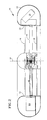
- Fig. 1 is a perspective showing of our unmanned flight vehicle, partially broken away to illustrate some of the equipment and payload carried within the vehicle fuselage.
- Fig. 2 is a cross-sectional showing through our flight vehicle to show the manner of mounting of the rotors and the rotor drive mechanisms.
- Fig. 3 is an illustration of the aerodynamics of our flight vehicle in hover and with collective pitch only applied to the rotor blades.
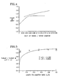
- Fig. 4 is a graph showing the ratio of the fuselage or shroud inlet lip radius to the rotor diameter plotted against a figure of merit to illustrate the inlet radius effect.
- Fig. 5 is a graph showing the ratio of the length or height of the fuselage duct through which air passes in passing through the rotors to the diameter of the rotors plotted against rotor thrust so generated divided by shroud thrust so generated to illustrate the duct length effect.
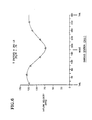
- Fig. 6 is a graph illustrating the inlet flow velocity variation or pattern at the various stations around the periphery of toroidal fuselage in which 180°, the nose of the vehicle, is the forward direction, and 0° and 360° are the aft direction or tail of the vehicle, caused by the application of cyclic pitch to the rotor blades.
- Fig. 7 is a representation of the aerodynamics of our vehicle in hover with both collective and cyclic pitch applied to the rotor blades to illustrate the pitching moments created by each.
- Fig. 8 is a graph of cyclic pitch input to the rotors plotted against the pitching moment created by the rotor and the pitching moment created by the fuselage in hover.
- Fig. 9 is an aerodynamic representation of our toroidal fuselage in forward flight to illustrate the velocity distribution of the air entering the fuselage duct to pass through the rotors.
- Fig. 10 is an aerodynamic representation of our vehicle showing our toroidal fuselage in forward flight to illustrate the pressure distribution on the fuselage caused by the velocity distribution illustrated in Fig. 9 so as to produce a nose-up pitching moment on the fuselage.
- Fig. 11 is an aerodynamic representation of our vehicle in forward flight with both cyclic and collective pitch applied to illustrate the opposite moments created by the rotor cyclic lift loads and the shroud cyclic lift loads.
- Fig. 12 is a graph showing the pitching moment created on the shroud and the rotor, separately, plotted against cyclic pitch input to the rotors to illustrate the effect of the application of cyclic pitch to the rotors, and its effect upon the pitching moment created by the shroud and the pitching moment created by the rotor.
- Fig. 13 is a diagrammatic representation of the counter-rotating rotors of our flight vehicle to illustrate how the forces and moments created by one rotor are cancelled by the forces and moments created by the other rotor.
- Fig. 14a is a diagrammatic representation of our flight vehicle illustrating how vehicle lift is controlled.
- Fig. 14b is a diagrammatic representation of our flight vehicle illustrating how vehicle pitch is controlled.
- Fig. 14c is a diagrammatic representation of our flight vehicle illustrating how vehicle roll is controlled.
- Fig. 14d is a diagrammatic representation of our flight vehicle illustrating how vehicle yaw is controlled.
- FIG. 1 we see our unmanned flight vehicle 10 which comprises toroidal shroud or fuselage 12, and counter-rotating multi-bladed rotors 16 and 18 positioned therewithin so as to be rotatable about axes of rotation coincident with fuselage axis 14.
- a plurality of support struts 20 extend from the inner periphery of toroidal fuselage 12 radially inwardly to support rotor housing 22.
- Support strut 20 extends into and is rigidly attached in conventional fashion or bonded to fuselage 12 such that a rigid structure is formed.
- Toroidal fuselage 12 is substantially hollow and is therefore capable of carrying fuel tanks such as 30 on diametrically opposite sides thereof, and other necessary cargo and equipment such as some sort of a payload 32, which may be a sensor or the like, at the 180° nose position of the toroidal fuselage so as to balance the engine 24.
- Additional equipment such as avionic equipment 34 and navigation equipment 36 can be selectively positioned within the hollow fuselage 12, and other electronic devices such as data links and data antennae would be positioned diametrically opposite the aviation and navigation equipment to keep the vehicle 10 balanced and in trim.
- Fuselage 12 and struts 20 are preferably made of composite material such as a plurality of high tensile strength fibers bonded in epoxy resin to produce both a strong and a light weight structure. Fuselage 12 is also, importantly, a closed toroid to produce a maximum strength structure.
- Fig. 2 we see the manner in which the counter-rotating rotors 16 and 18 are driven by engine 24 which is positioned within toroidal fuselage 12.
- appropriate clutch and drive mechanism drives drive shaft 40, which extends through hollow support strut 20 and between fuselage 12 and rotor housing 22, drives conventional gearing, shown at 42a and 42b, to drive rotors 16 and 18 about toroid axis and their own axis of rotation 14 in a counter rotating fashion.
- Each rotor is provided with a conventional swashplate mechanism 44a and 44b, which are controlled by electronic servos, such as the one shown at 46, to selectively impart both cyclic blade change and collective blade change to the blades of rotors 16 and 18.
- Rotors 16 and 18 are preferably of the rigid rotor type, rather than the articulated type.
- Swashplates 44a, 44b, and their related mechanism may be of the type shown in U.S. Patents Nos. 2,957,527 and 3,409,249 and the electronic servo system may be of the disclosed in U.S. Patent Application No. 07/454,488 filed December 21, 1989, and entitled Servo Control System For a Co-axial Rotary Winged Aircraft by J. Cycon et al.
- Engine 24 is preferably positioned diametrically opposite a payload such as shown at 32 for purposes of vehicle balance. Payload 32 could preferably be a conventional electronic sensor.
- a data link and a data link antenna are installed so that the data collected by the vehicle can be transmitted to ground control.
- Inlet screen 27, shown partially in Fig. 1, is positioned so as to cover the inlet of duct 54 of fuselage 12 to protect the rotors from foreign objects.
- Fig. 3 demonstrates the aerodynamics of our flight vehicle in hover and with collective pitch only applied. It will be noted by viewing Fig. 3 that with rotor 16 in operation and under collective pitch only, lift forces are being generated by the rotor and also at the inlet section of fuselage 12. This is because as the rotor rotates, it draws air into and across the inlet 52 of fuselage 12 at a high velocity, thereby inducing a suction at shroud inlet 52 so as to produce the lift effect on the shroud or fuselage 12 as shown in Fig. 3. It will therefore be seen that in our vehicle, lift is being generated by both the rotor and the shroud, and these lift forces are additive. By proper design of inlet 52 of the fuselage 12, and rotor placement, the fuselage 12 and rotor 16 can be caused to selectively share the lift generating function, and approximate equal sharing would be preferred.
- Fig. 4 shows curves plotted for two sets of data. Each curve clearly shows that as the lip radius to propeller ratio increases, the efficiency of the system increases. The curves also demonstrate that at about .04 ratio of inlet lip radius to propeller diameter, the figure of merit is about 0.7, and increases very little above that ratio, but drops off drastically below that ratio.
- Fig. 5 is a graph of the length of duct 54-to-the diameter of rotors 16 or 18 plotted against the ratio of the thrust generated by the rotor to the thrust generated by the fuselage.
- the graph of Fig. 5 demonstrates that the greater the height or length of the toroidal fuselage duct 54, the greater the change of achieving a 50-50 split between rotor thrust and shroud thrust or lift, assuming a proper selection of radius as discussed in connection with Fig. 4.
- Fig. 6 is a graph of the inflow velocity to duct 54 against the various azimuthal positions around fuselage 12 and in which 0° and 360° represent the rear or tail direction station and 180° represents the most forward or nose station on the fuselage 12.
- Fig. 6 is a graph of the inflow velocity to duct 54 against the various azimuthal positions around fuselage 12 and in which 0° and 360° represent the rear or tail direction station and 180° represents the most forward or nose station on the fuselage 12.
- Fig. 7 The effect of cyclic pitch application to the blades of rotors 16 and 18 within fuselage 12 is illustrated in Fig. 7 in which our vehicle 10 is shown in hover, and in the collective pitch condition shown in Fig. 6, but with cyclic pitch added thereto. It will be noted by viewing Fig. 7 that with both collective and cyclic pitch applied to the rotors of vehicle 10 in hover, both the fuselage 12 and rotor 16 are generating lift, that these lifts are additive, and that both the rotor and the shroud are generating pitching moments illustrated as M S and M R , respectively, which are also additive.
- Fig. 8 is a graph of pitching moment of each the rotor and the fuselage plotted against the degrees of cyclic pitch applied to rotors 16 and 18. It will be noted that of the total moment produced by vehicle 12 in the Fig. 7 condition, a substantial amount of the total moment is produced by the shroud, as compared to the moment produced by the rotor. Therefore, changes in rotor loading produce changes in the shroud loading or pitching moment and, therefore, in the system moment. This rotor control amplification becomes very important when one examines the forward flight characteristics of our vehicle 10.
- Fig. 9 illustrates the airflow distribution over inlet 52 of toroidal fuselage 12 during forward flight.
- the free stream velocity in forward flight V O is additive to and serves to increase the velocity over the 180° or forward station of toroidal shroud or fuselage 12, and to decrease the inlet velocity at the aft most 360° station so that the resulting inflow velocity at the 180° station is substantially larger than the velocity of the air entering fuselage 12 at the aft or 360° station.
- This results in a pressure or lift distribution differential illustrated in Fig. 10 which is substantially larger at the 180° forward station shown on the left in Figs. 9 and 10 then at the aft 360° station shown on the right of Figs. 9 and 10, thus producing the nose-up moment illustrated in Fig. 10 as fuselage 12 moves in forward flight.
- Fig. 11 in which it will be noted that the lift or moment creating characteristics of fuselage 12 remain as illustrated in Fig. 10, but so as to produce nose-up moment M S .
- cyclic pitch is applied so as to cause the flow of inlet air into the shroud duct 54 to be maximum at the 0° or aft station as shown in Fig. 6, a counteracting nose-down moment is created on the fuselage which coacts with the nose-down moment M R produced by rotor 16.
- Rotor phasing is the azimuthal position at which a blade from rotor 16 passes directly over the blade from rotor 18. This can be appreciated by viewing Fig.
- Fig. 14a illustrates our vehicle 10 in a lift control condition. This is produced by applying collective pitch, in equal amounts, to rotors 16 and 18.
- Fig. 14c in which lateral cyclic pitch is applied to rotors 16 and 18 in equal amounts so as to shift the center of pressure and lift leftwardly as illustrated in Fig. 14c so as to create a rotor moment causing vehicle 10 to roll in a clockwise direction, and similarly, as described in connection with Figs. 7 and 8, creating a shroud rolling moment additive to the rotor rolling moment.
- differential collective pitch is applied to rotors 16 and 18, thereby producing a torque differential which will cause yaw or rotating motion of our vehicle 10.
- Still another advantage of our construction is that appropriate application of rotor cyclic pitch will reduce vehicle stress and vibration. This is accomplished by selectively applying longitudinal cyclic and lateral cyclic pitch to the blades of rotors 16 and 18 so as to bring the centers of lift of each rotor closer to axis of rotation 14, and thereby reduce the moment which these centers of lift create, thereby also reducing the load which they impose upon the blades.
- This reduced load upon the blades of rotors 16 and 18 reduces stress on both the blades and in the control system used to control the blades. This reduced loading of the blades also reduces system vibration since these loads are vibratory loads.
Abstract
Description
- This invention relates to an unmanned flight vehicle wherein two counter-rotating rotors are positioned within a toroidal shroud or fuselage in which rotor pitch change is utilized to generate all required lift, pitch, roll and yaw control plus vibration and stress control, and to regulate the pattern and velocity of air flow into the toroidal fuselage to establish complimentary control forces on the fuselage which cooperate with the control forces generated by the rotors to provide all required flight controls for the vehicle.
- In the flight vehicle art, many propeller driven and circularly shaped vehicles have been tested, but they all require apparatus in addition and independent of the flight generating apparatus to control the flight of the vehicle. One of the most troublesome problems with the prior art designs is the nose-up pitching moment created during forward flight of the vehicle, and which must be compensated for. This nose-up moment encountered by the prior art was a limiting factor in these vehicles.
- An example of this prior art is the Hiller Flying Platform. The Hiller design incorporates two counter-rotating propellers surrounded by a shroud. The propellers were set at a fixed pitch and the amount of lift the propellers generated was controlled by the rotational speed of the propellers. The platform was stabilized and controlled in forward flight by a man leaning back and forth thereby creating a moment about the center of gravity of the platform. In later designs, flow vanes were installed below the propellers to act as additional control surfaces.
- Another example of the prior art is AROD, Airborne Remotely Operated Device. AROD incorporates a single rigid propeller in a shroud. Torque to counteract the propeller torque is obtained by placing flow vanes below the propeller. These vanes are movable and deflected proportionally to the amount of anti-torque required. These vanes were also used to control the vehicle in both pitch and roll. Because AROD used only a single propeller, gyroscopic coupling of aircraft pitch and roll existed, and a cross rate feedback control system was required to stabilize the air vehicle.
- While Sikorsky Aircraft has used counter-rotating rotors, such rotors were unshrouded. Further, while Aerospatiale has used a single shrouded fan as an anti-torque tail rotor for a helicopter, that single shrouded fan had no cyclic pitch control.
- Therefore, it is an object of this invention to teach an unmanned flight vehicle which comprises two counter-rotating rotors positioned within a toroidal shroud or fuselage and in which pitch control of the rotors provides all flight control requirements of the vehicle including lift, pitch, roll and yaw control plus vibration and stress control.
- It is a further object of this invention to teach such a vehicle wherein the shroud or fuselage is a closed toroid so that it constitutes a strong structure, and which is fabricated of composite materials such that it is a light structure. The fuselage is fabricated and designed to house all necessary equipment and payload including surveillance and reconnaissance equipment, and other equipment which permit it to perform decoy, jamming, target designation, data acquisition, and harassment type missions.
- It is still a further object of this invention to teach such an unmanned aerial vehicle which is safe in operation, simple in construction, and survivable under anticipated operating conditions and capable of entering areas where manned vehicles could not penetrate.
- A further feature of this invention is that the toroidal shroud or fuselage houses all required propulsion, avionic, fuel, payload and other flight related hardware in such a fashion that the vehicle remains in balance.
- It is a very important feature of this invention that the counter-rotating rotors have capability for both collective and cyclic pitch control, and therefore operable, in cooperation with a toroidal fuselage or shroud to provide all required control of the vehicle in both hover and flight, thereby eliminating the requirement for additional surfaces or equipment to control the vehicle in flight.
- It is also an important feature of this invention that the toroidal fuselage is shaped, particularly the inlet thereof, such that there is the capability and advantage of selective distribution of system lift between the rotor and the fuselage or shroud.
- It is still an important teaching of this invention that blade cyclic pitch is utilized to effect the pattern of and velocity of air flow entering the inlet of the fuselage duct to thereby selectively control the lift generated by the fuselage to effect the desired control of the vehicle, whether pitch, roll or yaw.
- It is still a further feature of this invention to teach such a vehicle in which the rotors are supported from the toroidal fuselage by a plurality of support struts extending therebetween and fabricated of composite material to be of maximum strength and minimum weight, and also to be hollow so as to be capable of housing pitch control servos, the drive shaft between the fuselage housed engine and the rotors, and other desirable equipment such as stability gyros.
- It is still a further feature of our invention to teach such a vehicle in which the rotors cooperate to cancel the torque and gyroscopic loads which each generate.
- It is still a further object of this invention to teach such a vehicle including appropriate inlet air filtration to protect the rotor systems from foreign object damage.
- It is still a further feature of this invention that the enclosing of the rotors within the toroidal fuselage prevents the formation of tip vortices and obstructs the free radiation of sound waves, and also provides protection from operating personnel inadvertently being struck by a rotor blade.
- It is still a further object of this invention to teach such a vehicle which is capable of vertical take-off and landing.
- It is still a further important feature of this invention that the control moments produced by the application of cyclic pitch to the rotors are amplified by the control moments generated by the fuselage as a result thereof.
- Other objects, features and advantages of the invention will become apparent in light of the following description thereof.
- Fig. 1 is a perspective showing of our unmanned flight vehicle, partially broken away to illustrate some of the equipment and payload carried within the vehicle fuselage.
- Fig. 2 is a cross-sectional showing through our flight vehicle to show the manner of mounting of the rotors and the rotor drive mechanisms.
- Fig. 3 is an illustration of the aerodynamics of our flight vehicle in hover and with collective pitch only applied to the rotor blades.
- Fig. 4 is a graph showing the ratio of the fuselage or shroud inlet lip radius to the rotor diameter plotted against a figure of merit to illustrate the inlet radius effect.
- Fig. 5 is a graph showing the ratio of the length or height of the fuselage duct through which air passes in passing through the rotors to the diameter of the rotors plotted against rotor thrust so generated divided by shroud thrust so generated to illustrate the duct length effect.
- Fig. 6 is a graph illustrating the inlet flow velocity variation or pattern at the various stations around the periphery of toroidal fuselage in which 180°, the nose of the vehicle, is the forward direction, and 0° and 360° are the aft direction or tail of the vehicle, caused by the application of cyclic pitch to the rotor blades.
- Fig. 7 is a representation of the aerodynamics of our vehicle in hover with both collective and cyclic pitch applied to the rotor blades to illustrate the pitching moments created by each.
- Fig. 8 is a graph of cyclic pitch input to the rotors plotted against the pitching moment created by the rotor and the pitching moment created by the fuselage in hover.
- Fig. 9 is an aerodynamic representation of our toroidal fuselage in forward flight to illustrate the velocity distribution of the air entering the fuselage duct to pass through the rotors.
- Fig. 10 is an aerodynamic representation of our vehicle showing our toroidal fuselage in forward flight to illustrate the pressure distribution on the fuselage caused by the velocity distribution illustrated in Fig. 9 so as to produce a nose-up pitching moment on the fuselage.
- Fig. 11 is an aerodynamic representation of our vehicle in forward flight with both cyclic and collective pitch applied to illustrate the opposite moments created by the rotor cyclic lift loads and the shroud cyclic lift loads.
- Fig. 12 is a graph showing the pitching moment created on the shroud and the rotor, separately, plotted against cyclic pitch input to the rotors to illustrate the effect of the application of cyclic pitch to the rotors, and its effect upon the pitching moment created by the shroud and the pitching moment created by the rotor.
- Fig. 13 is a diagrammatic representation of the counter-rotating rotors of our flight vehicle to illustrate how the forces and moments created by one rotor are cancelled by the forces and moments created by the other rotor.
- Fig. 14a is a diagrammatic representation of our flight vehicle illustrating how vehicle lift is controlled.
- Fig. 14b is a diagrammatic representation of our flight vehicle illustrating how vehicle pitch is controlled.
- Fig. 14c is a diagrammatic representation of our flight vehicle illustrating how vehicle roll is controlled.
- Fig. 14d is a diagrammatic representation of our flight vehicle illustrating how vehicle yaw is controlled.
- Referring to Fig. 1, we see our
unmanned flight vehicle 10 which comprises toroidal shroud orfuselage 12, and counter-rotatingmulti-bladed rotors fuselage axis 14. A plurality ofsupport struts 20 extend from the inner periphery oftoroidal fuselage 12 radially inwardly to supportrotor housing 22.Support strut 20 extends into and is rigidly attached in conventional fashion or bonded tofuselage 12 such that a rigid structure is formed. - An
engine 24 is located at the 0° or 360° tail station oftoroidal fuselage 12 and serves as the propulsion unit forvehicle 10. Air enters the engine housing throughinlet 26.Toroidal fuselage 12 is substantially hollow and is therefore capable of carrying fuel tanks such as 30 on diametrically opposite sides thereof, and other necessary cargo and equipment such as some sort of apayload 32, which may be a sensor or the like, at the 180° nose position of the toroidal fuselage so as to balance theengine 24. Additional equipment such asavionic equipment 34 andnavigation equipment 36 can be selectively positioned within thehollow fuselage 12, and other electronic devices such as data links and data antennae would be positioned diametrically opposite the aviation and navigation equipment to keep thevehicle 10 balanced and in trim. -
Fuselage 12 and struts 20 are preferably made of composite material such as a plurality of high tensile strength fibers bonded in epoxy resin to produce both a strong and a light weight structure.Fuselage 12 is also, importantly, a closed toroid to produce a maximum strength structure. - Now referring to Fig. 2, we see the manner in which the
counter-rotating rotors engine 24 which is positioned withintoroidal fuselage 12. In conventional fashion, appropriate clutch and drive mechanism drives driveshaft 40, which extends throughhollow support strut 20 and betweenfuselage 12 androtor housing 22, drives conventional gearing, shown at 42a and 42b, to driverotors rotation 14 in a counter rotating fashion. Each rotor is provided with aconventional swashplate mechanism rotors Rotors Swashplates Engine 24 is preferably positioned diametrically opposite a payload such as shown at 32 for purposes of vehicle balance.Payload 32 could preferably be a conventional electronic sensor. A data link and a data link antenna are installed so that the data collected by the vehicle can be transmitted to ground control. -
Inlet screen 27, shown partially in Fig. 1, is positioned so as to cover the inlet ofduct 54 offuselage 12 to protect the rotors from foreign objects. - To best understand the operation and advantages of our flight vehicle, reference will now be made to Fig. 3 which demonstrates the aerodynamics of our flight vehicle in hover and with collective pitch only applied. It will be noted by viewing Fig. 3 that with
rotor 16 in operation and under collective pitch only, lift forces are being generated by the rotor and also at the inlet section offuselage 12. This is because as the rotor rotates, it draws air into and across theinlet 52 offuselage 12 at a high velocity, thereby inducing a suction atshroud inlet 52 so as to produce the lift effect on the shroud orfuselage 12 as shown in Fig. 3. It will therefore be seen that in our vehicle, lift is being generated by both the rotor and the shroud, and these lift forces are additive. By proper design ofinlet 52 of thefuselage 12, and rotor placement, thefuselage 12 androtor 16 can be caused to selectively share the lift generating function, and approximate equal sharing would be preferred. - The effect of the radius of
inlet 52 offuselage 12 is best understood by viewing Fig. 4 wherein the ratio of the inlet lip radius of the fuselage to the propeller diameter is plotted against the figure of merit which is the actual power required to create lift in a particular vehicle versus the ideal power to accomplish this. Fig. 4 shows curves plotted for two sets of data. Each curve clearly shows that as the lip radius to propeller ratio increases, the efficiency of the system increases. The curves also demonstrate that at about .04 ratio of inlet lip radius to propeller diameter, the figure of merit is about 0.7, and increases very little above that ratio, but drops off drastically below that ratio. - Now viewing Fig. 5, we see the effects of the length or height of the
duct 54 created by the inner periphery (See Fig. 2) offuselage 12. Fig. 5 is a graph of the length of duct 54-to-the diameter ofrotors toroidal fuselage duct 54, the greater the change of achieving a 50-50 split between rotor thrust and shroud thrust or lift, assuming a proper selection of radius as discussed in connection with Fig. 4. With the fuselage and rotor sharing the load, smaller rotors can be used and, therefore, the size and weight of the vehicle can be reduced. - A very important effect is achieved in our vehicle when cyclic pitch is applied to the blades of
rotors toroidal fuselage 12 since, as shown in Fig. 6, which is a graph of the inflow velocity toduct 54 against the various azimuthal positions aroundfuselage 12 and in which 0° and 360° represent the rear or tail direction station and 180° represents the most forward or nose station on thefuselage 12. It will be noted that when cyclic pitch is applied to the rotor blades, the inflow velocity distribution is caused to vary and produces a pitching moment about the vehicle center of gravity due to this inflow variation. By selective application of cyclic pitch, the inflow velocity can be maximum or minimum at any of the selected shroud stations shown in Fig. 6. - The effect of cyclic pitch application to the blades of
rotors fuselage 12 is illustrated in Fig. 7 in which ourvehicle 10 is shown in hover, and in the collective pitch condition shown in Fig. 6, but with cyclic pitch added thereto. It will be noted by viewing Fig. 7 that with both collective and cyclic pitch applied to the rotors ofvehicle 10 in hover, both thefuselage 12 androtor 16 are generating lift, that these lifts are additive, and that both the rotor and the shroud are generating pitching moments illustrated as MS and MR, respectively, which are also additive. - To appreciate the magnitude of the pitching moment of the
fuselage 12 androtor 16, reference will now be made to the graph shown in Fig. 8 which is a graph of pitching moment of each the rotor and the fuselage plotted against the degrees of cyclic pitch applied torotors vehicle 12 in the Fig. 7 condition, a substantial amount of the total moment is produced by the shroud, as compared to the moment produced by the rotor. Therefore, changes in rotor loading produce changes in the shroud loading or pitching moment and, therefore, in the system moment. This rotor control amplification becomes very important when one examines the forward flight characteristics of ourvehicle 10. - It should be borne in mind that, as explained earlier, a failing of the prior art flight vehicles was the need to utilize complicated and heavy equipment to counteract the nose-up moment generated during flight. We will now describe how this nose-up moment is generated and how our invention overcomes the nose-up moment encountered in forward flight without the need for additional controls or equipment.
- Fig. 9 illustrates the airflow distribution over
inlet 52 oftoroidal fuselage 12 during forward flight. It will be noted that the free stream velocity in forward flight VO is additive to and serves to increase the velocity over the 180° or forward station of toroidal shroud orfuselage 12, and to decrease the inlet velocity at the aft most 360° station so that the resulting inflow velocity at the 180° station is substantially larger than the velocity of theair entering fuselage 12 at the aft or 360° station. This results in a pressure or lift distribution differential illustrated in Fig. 10 which is substantially larger at the 180° forward station shown on the left in Figs. 9 and 10 then at the aft 360° station shown on the right of Figs. 9 and 10, thus producing the nose-up moment illustrated in Fig. 10 asfuselage 12 moves in forward flight. - Now considering our
vehicle 10 in forward flight, and with both collective and cyclic pitch applied torotors 16 an 18, attention is called to Fig. 11 in which it will be noted that the lift or moment creating characteristics offuselage 12 remain as illustrated in Fig. 10, but so as to produce nose-up moment MS. However, when cyclic pitch is applied so as to cause the flow of inlet air into theshroud duct 54 to be maximum at the 0° or aft station as shown in Fig. 6, a counteracting nose-down moment is created on the fuselage which coacts with the nose-down moment MR produced byrotor 16. - By viewing Fig. 12, we see the magnitude of the pitching moment of the fuselage MS and the moment of the rotor MR plotted against degrees of cyclic pitch applied to
rotors fuselage 12 is about 1650 lbs.. However, as cyclic pitch is applied torotors fuselage 12 decreases rapidly, while the nose-down moment created by the rotor MR increases slowly, so that at -11° cyclic pitch, the nose-up moment MS of the shroud orfuselage 12 is balanced by the nose-down moment MR created by the rotor, such that thevehicle 10 is in a trimmed condition. - Considering our solution to the nose-up problem of the prior art, we may consider this matter mathematically. When we consider that the moment acting upon the vehicle is the moment created by the fuselage, which is a nose-up moment in forward flight, less the moment created by the rotor, which is generally a nose-down moment in forward flight. We can therefore establish the equation:
- Equation #1:

- During forward flight MShroud = MFF - MCS, where MFF is the moment created by the fuselage normally during forward flight, and MCS is the moment created by the fuselage to the application of cyclic pitch to the rotors. Accordingly, the equation for forward flight is:
- Equation #2

- For the forward flight condition of our
vehicle 10 at 70 knots, generating 300 lbs. of rotor thrust, with a -5° forward pitch, which is the condition illustrated in the graph of Fig. 12, it will be noted that with the increased application of cyclic pitch, the quantity of moment MCS increases such that at -11° cyclic pitch, the quantity of nose-up (MFF -MCS) is equal to the rotor nose-down moment MR, and therefore the vehicle is in trim. It will therefore be seen that the nose-up pitching moment created by the fuselage in forward flight has been brought into balance by the application of cyclic pitch to the rotor. - Another advantage of our flight vehicle construction is that by the use of counter-rotating rigid rotors, some forces and moments created by
rotor 16 are cancelled by oppositely rotatingrotor 18 which forces and moments are cancelled as a function of rotor phasing. Rotor phasing is the azimuthal position at which a blade fromrotor 16 passes directly over the blade fromrotor 18. This can be appreciated by viewing Fig. 13 in which it will be noted that for a 60° phasing forces FY created byrotor 16 are cancelled by counteracting forces FY and FX generated byrotor 18, while the lifting forces FX and FZ of the rotors are additive but at a 0° phasing FX and FZ fromrotor 16 are cancelled by FX and FZ ofrotor 18, while FY fromrotor 16 is additive to FY ofrotor 18. Similarly, at 60° phasing, the moments MX, and MZ created byrotor 16 are cancelled by equal and opposite moments MX, MY and MZ created by oppositely rotatingrotor 18. In addition, the utilization of two counter rotating rotors also eliminates gyroscopic coupling of aircraft pitch and roll. - If one were to substitute a single rotor for our counter-rotating rotors, when such a vehicle experienced a pitching moment, a gyroscopic load would be created which would tend to also roll the vehicle, resulting in a cross-couple system. This would require the addition of a cross-rate feedback control system to the single rotor system. In addition, the single rotor system would require the addition of yaw control mechanisms.
- To demonstrate the our invention is capable of producing all required lift, pitch, roll and yaw control to
vehicle 10 without the need of any additional equipment, reference will now be made to Figs. 14a through 14d. - Fig. 14a illustrates our
vehicle 10 in a lift control condition. This is produced by applying collective pitch, in equal amounts, torotors - Pitch control is demonstrated in Fig. 14b wherein equal amounts of longitudinal cyclic pitch is applied to
rotors fuselage 12 and to also increase the lift and pitching moment generated at the 0° tail station offuselage 12, as illustrated in connection with Figs. 6 & 7. It will therefore be seen that the application of cyclic longitudinal pitch torotors - Now considering roll control, attention is called to Fig. 14c in which lateral cyclic pitch is applied to
rotors moment causing vehicle 10 to roll in a clockwise direction, and similarly, as described in connection with Figs. 7 and 8, creating a shroud rolling moment additive to the rotor rolling moment. - For yaw control, as illustrated in Fig. 14d, differential collective pitch is applied to
rotors vehicle 10. - Still another advantage of our construction is that appropriate application of rotor cyclic pitch will reduce vehicle stress and vibration. This is accomplished by selectively applying longitudinal cyclic and lateral cyclic pitch to the blades of
rotors rotation 14, and thereby reduce the moment which these centers of lift create, thereby also reducing the load which they impose upon the blades. This reduced load upon the blades ofrotors
Claims (17)
- A flight vehicle comprising:a. a toroidal fuselage concentric about an axis,b. two counter-rotating bladed rotors located within said toroidal fuselage,c. means to position said rotors for rotation about an axis of rotation which is coincident with the fuselage axis, andd. means to totally control the motions of said vehicle in lift, pitch, roll and yaw in both hover and forward flight comprising:1) means for applying both collective and cyclic pitch changes to the blades of said rotors so that the moments created by the rotors by the application of pitch change to the rotor blades cooperate with the moments created by airflow through said toroid fuselage to produce the desired lift, pitch, yaw and roll control of the flight vehicle.
- A flight vehicle according to Claim 1 wherein said last mentioned means is operable so that the nose-up pitching moment created by said toroidal fuselage in forward flight is compensated for by the application of cyclic pitch to said rotors to thereby change the pattern of air flowing into said toroidal fuselage so as to reduce the nose-up pitching moment created by the toroidal fuselage to a point where it is equal to the nose-down moment created by the rotors so as to effect vehicle trim.
- A flight vehicle according to Claim 1 wherein said toroidal fuselage is substantially hollow so as to provide space for carrying the necessary vehicle controls, payload, fuel and propulsion mechanism.
- A flight vehicle according to Claim 3 and including an engine supported by such fuselage and operable to generate a high velocity gas stream to propel said vehicle.
- A flight vehicle according to Claim 4 wherein said rotors are rigid rotors.
- A flight vehicle according to Claim 1 wherein the rotors are of a given diameter and the air inlet established by said toroidal fuselage is of a given radius, and wherein the ratio of the air inlet radius of the fuselage to the diameter is at least about .04.
- A flight vehicle according to Claim 5 wherein said rotors are supported from a rotor housing and said means positioning said rotors constitute a plurality of support struts extending from said toroidal fuselage radially inwardly to said rotor housing and each being operatively connected at their opposite ends to the housing and the fuselage, respectively, and wherein said toroidal fuselage and said support struts are fabricated of light-weight, composite material.
- A flight vehicle according to Claim 7 wherein said composite material comprises a plurality of high tensile strength fibers joined by cured epoxy resin to produce a light-weight and strong vehicle.
- A flight vehicle according to Claim 5 and wherein said fuselage is shaped as a closed toroid for structural integrity.
- A flight vehicle according to Claim 8 wherein said support struts are hollow, and including a rotor drive motor located in said fuselage, and a drive shaft system extending from said drive motor to said rotors to drive said rotors for rotation about said axis of rotation.
- A flight vehicle according to Claim 1 wherein each rotor of the counter-rotating rigid rotors cancels the torque, the gyroscopic coupling of aircraft pitch and roll, and the vibratory loads created by the other rotor so as to produce an uncoupled rotor system.
- In a flight vehicle according to Claim 1 including the method of controlling the lift applied to the vehicle comprising changing the collective pitch to the blades of at least one of said rotors to thereby produce lift creating forces on both the rotor and the fuselage.
- A flight vehicle according to Claim 1 including the method of controlling vehicle pitch comprising the selectively applying longitudinal cyclic pitch to the blades of at least one of said rotors to thereby produce pitch creating forces on both the rotor and the fuselage.
- A flight vehicle according to Claim 1 including the method of controlling vehicle roll comprising selectively applying lateral cyclic pitch to the blades of at least one of said rotors to thereby produce roll creating forces on both the rotor and the fuselage.
- A flight vehicle according to Claim 1 including the method of providing yaw control to said vehicle comprising the application of differential collective pitch to the blades of said rotors to thereby produce the required torque differential to effect yaw control.
- In a flight vehicle according to Claim 1, the method of abating the nose-up moment created by the toroidal fuselage during forward flight comprising selectively applying cyclic pitch to at least one of said rotors to selectively vary the pattern of air flowing into said fuselage to thereby produce a counteracting pitching moment on said toroidal fuselage to thereby reduce the total nose-up pitching moment created by the fuselage in forward flight until it is substantially equal to the nose-down pitching moment created by the rotors.
- In a flight vehicle according to Claim 1, the method of controlling vehicle vibration and stress comprising selectively applying cyclic pitch to at least one of said rotors to cause the rotor center of lift to shift toward the axis of rotation, thereby reducing the moment so imposed upon the rotor and, hence, the load and stress created thereby, while simultaneously reducing vehicle vibration caused by vibratory loads.
Applications Claiming Priority (2)
| Application Number | Priority Date | Filing Date | Title |
|---|---|---|---|
| US07/526,092 US5152478A (en) | 1990-05-18 | 1990-05-18 | Unmanned flight vehicle including counter rotating rotors positioned within a toroidal shroud and operable to provide all required vehicle flight controls |
| US526092 | 1990-05-18 |
Publications (3)
| Publication Number | Publication Date |
|---|---|
| EP0457710A2 true EP0457710A2 (en) | 1991-11-21 |
| EP0457710A3 EP0457710A3 (en) | 1992-01-15 |
| EP0457710B1 EP0457710B1 (en) | 1995-03-01 |
Family
ID=24095885
Family Applications (1)
| Application Number | Title | Priority Date | Filing Date |
|---|---|---|---|
| EP91630027A Expired - Lifetime EP0457710B1 (en) | 1990-05-18 | 1991-05-14 | An unmanned flight vehicle including counter rotating rotors positioned within a toroidal shroud and operable to provide all required vehicle flight controls |
Country Status (8)
| Country | Link |
|---|---|
| US (1) | US5152478A (en) |
| EP (1) | EP0457710B1 (en) |
| JP (1) | JP2911643B2 (en) |
| AU (1) | AU636484B2 (en) |
| CA (1) | CA2042235C (en) |
| DE (1) | DE69107677T2 (en) |
| IL (1) | IL98102A (en) |
| RU (1) | RU2062246C1 (en) |
Cited By (12)
| Publication number | Priority date | Publication date | Assignee | Title |
|---|---|---|---|---|
| WO1993003961A1 (en) * | 1991-08-13 | 1993-03-04 | United Technologies Corporation | Shroud geometry for unmanned aerial vehicles |
| FR2707248A1 (en) * | 1993-07-05 | 1995-01-13 | Thomson Csf | Self-propelled and remotely controlled flying machine fitted with a payload |
| WO2001053150A1 (en) * | 2000-01-20 | 2001-07-26 | Gyropter | Aircraft with rotary wings |
| FR2856378A1 (en) | 2003-06-18 | 2004-12-24 | Gaudeffroy Charles Mic Guilhot | ENHANCED SECURITY GYROPTER |
| EP1502852A1 (en) * | 2003-07-30 | 2005-02-02 | C.R.F. Società Consortile per Azioni | A flying machine |
| WO2005019027A1 (en) * | 2003-01-02 | 2005-03-03 | Dunagin Percy E Jr | Vertical lift aircraft having an enclosed rotary wing |
| FR2860211A1 (en) * | 2003-09-30 | 2005-04-01 | Gaudeffroy Michel Char Guilhot | Aircraft with multiple contrarotating rotors has automated control coupling mechanism for rotors |
| WO2010115255A1 (en) * | 2009-04-09 | 2010-10-14 | Jaime Brustolin | Aircraft capable of vertical flight, take-off and landing |
| DE102012105803A1 (en) | 2012-06-29 | 2014-01-02 | Dieter Herz | vehicle |
| EP2860107A1 (en) * | 2013-10-08 | 2015-04-15 | Sikorsky Aircraft Corporation | Yaw control of co-axial rotor |
| US10239615B2 (en) | 2014-01-07 | 2019-03-26 | 4525612 Canada Inc. | Personal flight vehicle |
| CN113022860A (en) * | 2021-05-24 | 2021-06-25 | 四川迅联达智能科技有限公司 | Electric control multifunctional differential course control system |
Families Citing this family (85)
| Publication number | Priority date | Publication date | Assignee | Title |
|---|---|---|---|---|
| EP0861779B1 (en) * | 1992-06-22 | 2002-11-20 | United Technologies Corporation | A rotor blade assembly for an unmanned aerial vehicle |
| RU2012512C1 (en) * | 1993-09-07 | 1994-05-15 | Фирма "ВИСТ" | Hybrid flying vehicle |
| US5370341A (en) * | 1994-04-05 | 1994-12-06 | Leon; Ross | Ultralight helicopter and control system |
| US5575438A (en) * | 1994-05-09 | 1996-11-19 | United Technologies Corporation | Unmanned VTOL ground surveillance vehicle |
| US5971325A (en) | 1997-12-23 | 1999-10-26 | Sikorsky Aircraft Corporation | Compensation for rotorcraft pitch axis control saturation |
| AU2251500A (en) * | 1998-08-27 | 2000-04-03 | Nicolae Bostan | Gyrostabilized self propelled aircraft |
| AU4324200A (en) * | 1998-12-11 | 2000-07-24 | Moller International, Inc. | Stabilizing control apparatus for robotic or remotely controlled flying platform |
| USD418475S (en) * | 1999-04-08 | 2000-01-04 | Milde Jr Karl F | Personal air transport |
| US6270038B1 (en) | 1999-04-22 | 2001-08-07 | Sikorsky Aircraft Corporation | Unmanned aerial vehicle with counter-rotating ducted rotors and shrouded pusher-prop |
| US6170778B1 (en) | 1999-04-22 | 2001-01-09 | Sikorsky Aircraft Corporation | Method of reducing a nose-up pitching moment on a ducted unmanned aerial vehicle |
| US6543726B2 (en) * | 1999-05-21 | 2003-04-08 | Vortex Holding Company | Fluid flow straightening techniques |
| USD430530S (en) * | 1999-12-09 | 2000-09-05 | Milde Jr Karl F | Personal air transport |
| US6848649B2 (en) | 2000-10-03 | 2005-02-01 | Charles Gilpin Churchman | V/STOL biplane aircraft |
| US6581872B2 (en) * | 2001-08-08 | 2003-06-24 | Eric Ronald Walmsley | Circular vertical take off & landing aircraft |
| US8500507B2 (en) | 2001-03-28 | 2013-08-06 | Steven Davis | Directionally controllable flying vehicle and a propeller mechanism for accomplishing the same |
| US8113905B2 (en) * | 2001-03-28 | 2012-02-14 | Steven Davis | Directionally controllable flying vehicle and a propeller mechanism for accomplishing the same |
| US6691949B2 (en) | 2001-07-06 | 2004-02-17 | The Charles Stark Draper Laboratory, Inc. | Vertical takeoff and landing aerial vehicle |
| US6672538B2 (en) * | 2002-05-23 | 2004-01-06 | Sikorsky Aircraft Corporation | Transmission for a coaxial counter rotating rotor system |
| WO2004101357A2 (en) | 2002-08-30 | 2004-11-25 | Qaxu Technology Inc. | Homeostatic flying hovercraft |
| EP1592594A2 (en) * | 2003-02-07 | 2005-11-09 | Anergy Holdings Ltd. | Levitating platform |
| JP2005144610A (en) * | 2003-11-17 | 2005-06-09 | Fanuc Ltd | Sensor cable wiring processing structure |
| RU2256585C1 (en) | 2004-01-20 | 2005-07-20 | Общество С Ограниченной Ответственностью "Мидера-К" | Propeller |
| US20050230525A1 (en) * | 2004-03-30 | 2005-10-20 | Paterro Von F C | Craft with magnetically curved space |
| US7520466B2 (en) * | 2005-03-17 | 2009-04-21 | Nicolae Bostan | Gyro-stabilized air vehicle |
| US7712701B1 (en) * | 2006-02-10 | 2010-05-11 | Lockheed Martin Corporation | Unmanned aerial vehicle with electrically powered, counterrotating ducted rotors |
| US7631834B1 (en) | 2006-02-24 | 2009-12-15 | Stealth Robotics, Llc | Aerial robot with dispensable conductive filament |
| US7510142B2 (en) * | 2006-02-24 | 2009-03-31 | Stealth Robotics | Aerial robot |
| US8087315B2 (en) | 2006-10-10 | 2012-01-03 | Honeywell International Inc. | Methods and systems for attaching and detaching a payload device to and from, respectively, a gimbal system without requiring use of a mechanical tool |
| US20080302920A1 (en) * | 2007-03-07 | 2008-12-11 | Mack Gerald L | Aerial Lifting and Propulsion Device (ALPD) |
| US7681832B2 (en) | 2007-05-02 | 2010-03-23 | Honeywell International Inc. | Ducted fan air vehicle with deployable wings |
| US8342442B1 (en) * | 2007-05-15 | 2013-01-01 | Dancila LLC | Advanced airship technologies |
| US8251307B2 (en) * | 2007-06-11 | 2012-08-28 | Honeywell International Inc. | Airborne manipulator system |
| US8200375B2 (en) | 2008-02-12 | 2012-06-12 | Stuckman Katherine C | Radio controlled aircraft, remote controller and methods for use therewith |
| US8091833B2 (en) * | 2008-02-29 | 2012-01-10 | Insitu, Inc. | Vibration isolation devices and associated systems and methods |
| KR101344777B1 (en) * | 2008-07-07 | 2014-01-15 | (주)선택이앤티 | Rotational bottom-blade type vehicle |
| US8109711B2 (en) * | 2008-07-18 | 2012-02-07 | Honeywell International Inc. | Tethered autonomous air vehicle with wind turbines |
| US8123460B2 (en) * | 2008-07-23 | 2012-02-28 | Honeywell International Inc. | UAV pod cooling using integrated duct wall heat transfer |
| US8387911B2 (en) * | 2008-07-25 | 2013-03-05 | Honeywell International Inc. | Ducted fan core for use with an unmanned aerial vehicle |
| US8070103B2 (en) * | 2008-07-31 | 2011-12-06 | Honeywell International Inc. | Fuel line air trap for an unmanned aerial vehicle |
| US20120234984A1 (en) * | 2008-08-06 | 2012-09-20 | Honeywell International Inc. | Integrated Duct Design for an Unmanned Aerial Vehicle |
| US8240597B2 (en) * | 2008-08-06 | 2012-08-14 | Honeywell International Inc. | UAV ducted fan lip shaping |
| US8543265B2 (en) * | 2008-10-20 | 2013-09-24 | Honeywell International Inc. | Systems and methods for unmanned aerial vehicle navigation |
| US8123169B2 (en) * | 2008-11-12 | 2012-02-28 | Honeywell International Inc. | Vertical non-bladdered fuel tank for a ducted fan vehicle |
| US8225822B2 (en) * | 2008-11-14 | 2012-07-24 | Honeywell International Inc. | Electric fueling system for a vehicle that requires a metered amount of fuel |
| US20110001017A1 (en) * | 2008-12-08 | 2011-01-06 | Honeywell International Inc. | Uav ducted fan swept and lean stator design |
| US8328130B2 (en) * | 2008-12-08 | 2012-12-11 | Honeywell International Inc. | Vertical take off and landing unmanned aerial vehicle airframe structure |
| US8375837B2 (en) * | 2009-01-19 | 2013-02-19 | Honeywell International Inc. | Catch and snare system for an unmanned aerial vehicle |
| US8348190B2 (en) | 2009-01-26 | 2013-01-08 | Honeywell International Inc. | Ducted fan UAV control alternatives |
| US8205820B2 (en) * | 2009-02-03 | 2012-06-26 | Honeywell International Inc. | Transforming unmanned aerial-to-ground vehicle |
| US20100215212A1 (en) * | 2009-02-26 | 2010-08-26 | Honeywell International Inc. | System and Method for the Inspection of Structures |
| US20100228406A1 (en) * | 2009-03-03 | 2010-09-09 | Honeywell International Inc. | UAV Flight Control Method And System |
| US20110180667A1 (en) * | 2009-03-10 | 2011-07-28 | Honeywell International Inc. | Tether energy supply system |
| WO2011159374A2 (en) * | 2010-03-08 | 2011-12-22 | The Penn State Research Foundation | Double-ducted fan |
| US9004393B2 (en) | 2010-10-24 | 2015-04-14 | University Of Kansas | Supersonic hovering air vehicle |
| WO2012063220A2 (en) | 2010-11-12 | 2012-05-18 | Sky Sapience | Aerial unit and method for elevating payloads |
| US9004973B2 (en) | 2012-10-05 | 2015-04-14 | Qfo Labs, Inc. | Remote-control flying copter and method |
| EP2738091B1 (en) | 2012-11-30 | 2015-07-22 | AIRBUS HELICOPTERS DEUTSCHLAND GmbH | Vertical take-off and landing (VTOL) aerial vehicle and method of operating such a VTOL aerial vehicle |
| SG2013004940A (en) * | 2013-01-21 | 2014-08-28 | Singapore Tech Aerospace Ltd | Method for improving crosswind stability of a propeller duct and a corresponding apparatus, system and computer readable medium |
| US9290269B2 (en) | 2013-03-15 | 2016-03-22 | CyPhy Works, Inc. | Spooler for unmanned aerial vehicle system |
| EP2878433B1 (en) | 2013-11-29 | 2016-04-20 | AIRBUS HELICOPTERS DEUTSCHLAND GmbH | Shrouded rotary assembly from segmented composite for aircraft and method for its manufacture |
| US10107196B2 (en) | 2014-08-08 | 2018-10-23 | Thomas International, Inc. | Adjustable size inlet system |
| USD780665S1 (en) * | 2015-02-16 | 2017-03-07 | John Jeffrey Blincow | Space station |
| US10814966B2 (en) | 2015-05-25 | 2020-10-27 | Dotterel Technologies Limited | Shroud for an aircraft |
| US10464668B2 (en) | 2015-09-02 | 2019-11-05 | Jetoptera, Inc. | Configuration for vertical take-off and landing system for aerial vehicles |
| EP3363732B1 (en) | 2015-09-02 | 2020-10-14 | Jetoptera, Inc. | Ejector and airfoil configurations |
| US11001378B2 (en) | 2016-08-08 | 2021-05-11 | Jetoptera, Inc. | Configuration for vertical take-off and landing system for aerial vehicles |
| US9815552B1 (en) * | 2015-09-21 | 2017-11-14 | Amazon Technologies, Inc. | Unmanned aerial vehicle with center mounted fuselage and closed wing |
| ITUB20153894A1 (en) * | 2015-09-25 | 2017-03-25 | Skybox Eng S R L | Drone structure with high aerodynamic efficiency |
| US10258888B2 (en) | 2015-11-23 | 2019-04-16 | Qfo Labs, Inc. | Method and system for integrated real and virtual game play for multiple remotely-controlled aircraft |
| USD817252S1 (en) * | 2016-04-19 | 2018-05-08 | Samsung Electronics Co., Ltd. | Drone |
| USD817251S1 (en) * | 2016-04-19 | 2018-05-08 | Samsung Electronics Co., Ltd. | Drone |
| USD815580S1 (en) * | 2016-04-19 | 2018-04-17 | Samsung Electronics Co., Ltd. | Drone |
| CN107323666B (en) * | 2016-04-28 | 2020-11-06 | 深圳富泰宏精密工业有限公司 | Unmanned aerial vehicle |
| US10625858B2 (en) | 2016-08-08 | 2020-04-21 | Cleo Robotics Inc. | Flight control for an unmanned aerial vehicle |
| USD813315S1 (en) * | 2016-11-18 | 2018-03-20 | Eric Sweeney | Flying disk |
| EP3366586B1 (en) * | 2017-02-27 | 2020-08-19 | AIRBUS HELICOPTERS DEUTSCHLAND GmbH | A thrust producing unit with at least two rotor assemblies and a shrouding |
| CN110914149A (en) * | 2017-06-27 | 2020-03-24 | 博纳维德(控股)有限公司 | Rotor type unmanned aerial vehicle |
| JP7155174B2 (en) | 2017-06-27 | 2022-10-18 | ジェトプテラ、インコーポレイテッド | Aircraft vertical take-off and landing system configuration |
| WO2019022618A1 (en) | 2017-07-24 | 2019-01-31 | Dotterel Technologies Limited | Shroud |
| US10423831B2 (en) | 2017-09-15 | 2019-09-24 | Honeywell International Inc. | Unmanned aerial vehicle based expansion joint failure detection system |
| US10583924B2 (en) * | 2017-10-01 | 2020-03-10 | Petru A. Simionescu | Vertical takeoff and landing unmanned aerial vehicle (VTOL-UAV) |
| US11712637B1 (en) | 2018-03-23 | 2023-08-01 | Steven M. Hoffberg | Steerable disk or ball |
| AU2019271730A1 (en) | 2018-05-16 | 2020-12-24 | Dotterel Technologies Limited | Systems and methods for audio capture |
| DE102022122257B3 (en) | 2022-09-02 | 2024-03-07 | Tom Bauer | Flying disc with jacketed double rotor |
| CN115246477B (en) * | 2022-09-21 | 2022-12-23 | 北京航空航天大学 | Rotation self-balancing mooring unmanned aerial vehicle |
Citations (2)
| Publication number | Priority date | Publication date | Assignee | Title |
|---|---|---|---|---|
| DE1756219A1 (en) * | 1968-04-23 | 1972-01-27 | Wolfgang Haimerl | Flying disc |
| US4796836A (en) * | 1985-02-28 | 1989-01-10 | Dieter Schatzmayr | Lifting engine for VTOL aircrafts |
Family Cites Families (11)
| Publication number | Priority date | Publication date | Assignee | Title |
|---|---|---|---|---|
| US2935275A (en) * | 1955-10-20 | 1960-05-03 | Leonard W Grayson | Disc shaped aircraft |
| US3002709A (en) * | 1955-12-19 | 1961-10-03 | C L Cochran And Associates | Aircraft adapted for vertical ascent and descent |
| US3103327A (en) * | 1956-04-12 | 1963-09-10 | Charles B Bolton | Helicopter control system |
| US2966318A (en) * | 1959-05-12 | 1960-12-27 | Chodan Ivan | Variable pitch means for vertically rising plane |
| FR75976E (en) * | 1959-07-01 | 1961-09-01 | R L Cie De Rech S Et D Etudes | Improvements to air navigation devices |
| US3409249A (en) * | 1966-06-29 | 1968-11-05 | United Aircraft Corp | Coaxial rigid rotor helicopter and method of flying same |
| US3477168A (en) * | 1967-03-20 | 1969-11-11 | James E Trodglen Jr | Internal combustion engine powered flying toys |
| GB1523714A (en) * | 1971-12-13 | 1978-09-06 | Westland Aircraft Ltd | Helicopters |
| DE2718178A1 (en) * | 1977-04-23 | 1978-11-02 | Mueller Mahn Werner | Coated wing for vertical take=off aircraft - is either elliptical or oval in plan view and pointed towards front |
| US4196877A (en) * | 1977-06-15 | 1980-04-08 | Mutrux Jean L | Aircraft |
| US5035377A (en) * | 1985-02-28 | 1991-07-30 | Technolizenz Establishment | Free standing or aircraft lift generator |
-
1990
- 1990-05-18 US US07/526,092 patent/US5152478A/en not_active Expired - Lifetime
-
1991
- 1991-05-08 AU AU76426/91A patent/AU636484B2/en not_active Ceased
- 1991-05-09 CA CA002042235A patent/CA2042235C/en not_active Expired - Fee Related
- 1991-05-10 IL IL98102A patent/IL98102A/en not_active IP Right Cessation
- 1991-05-14 EP EP91630027A patent/EP0457710B1/en not_active Expired - Lifetime
- 1991-05-14 DE DE69107677T patent/DE69107677T2/en not_active Expired - Fee Related
- 1991-05-16 JP JP3140944A patent/JP2911643B2/en not_active Expired - Fee Related
- 1991-05-17 RU SU4895433/23A patent/RU2062246C1/en not_active IP Right Cessation
Patent Citations (2)
| Publication number | Priority date | Publication date | Assignee | Title |
|---|---|---|---|---|
| DE1756219A1 (en) * | 1968-04-23 | 1972-01-27 | Wolfgang Haimerl | Flying disc |
| US4796836A (en) * | 1985-02-28 | 1989-01-10 | Dieter Schatzmayr | Lifting engine for VTOL aircrafts |
Cited By (21)
| Publication number | Priority date | Publication date | Assignee | Title |
|---|---|---|---|---|
| WO1993003961A1 (en) * | 1991-08-13 | 1993-03-04 | United Technologies Corporation | Shroud geometry for unmanned aerial vehicles |
| FR2707248A1 (en) * | 1993-07-05 | 1995-01-13 | Thomson Csf | Self-propelled and remotely controlled flying machine fitted with a payload |
| WO2001053150A1 (en) * | 2000-01-20 | 2001-07-26 | Gyropter | Aircraft with rotary wings |
| FR2804082A1 (en) * | 2000-01-20 | 2001-07-27 | Gyropter | Rotary wing aircraft or gyrocopter has contra-rotating rotors with variable-pitch blades controlled by rocking rings and concentric crowns |
| WO2005019027A1 (en) * | 2003-01-02 | 2005-03-03 | Dunagin Percy E Jr | Vertical lift aircraft having an enclosed rotary wing |
| FR2856378A1 (en) | 2003-06-18 | 2004-12-24 | Gaudeffroy Charles Mic Guilhot | ENHANCED SECURITY GYROPTER |
| WO2004113166A1 (en) | 2003-06-18 | 2004-12-29 | Michel Guilhot-Gaudeffroy | Gyropter having increased safety |
| EP1502852A1 (en) * | 2003-07-30 | 2005-02-02 | C.R.F. Società Consortile per Azioni | A flying machine |
| FR2860211A1 (en) * | 2003-09-30 | 2005-04-01 | Gaudeffroy Michel Char Guilhot | Aircraft with multiple contrarotating rotors has automated control coupling mechanism for rotors |
| WO2010115255A1 (en) * | 2009-04-09 | 2010-10-14 | Jaime Brustolin | Aircraft capable of vertical flight, take-off and landing |
| DE102012105803A1 (en) | 2012-06-29 | 2014-01-02 | Dieter Herz | vehicle |
| WO2014000889A2 (en) | 2012-06-29 | 2014-01-03 | Herz Dieter | Vehicle |
| DE202013012094U1 (en) | 2012-06-29 | 2015-06-17 | Dieter Herz | vehicle |
| DE102012105803B4 (en) | 2012-06-29 | 2022-11-03 | Dieter Herz | vehicle |
| EP2860107A1 (en) * | 2013-10-08 | 2015-04-15 | Sikorsky Aircraft Corporation | Yaw control of co-axial rotor |
| US9452829B2 (en) | 2013-10-08 | 2016-09-27 | Sikorsky Aircraft Corporation | Yaw control of co-axial rotor |
| US10239615B2 (en) | 2014-01-07 | 2019-03-26 | 4525612 Canada Inc. | Personal flight vehicle |
| US10464671B2 (en) | 2014-01-07 | 2019-11-05 | 4525612 Canada Inc. | Personal flight vehicle |
| US10710718B2 (en) | 2014-01-07 | 2020-07-14 | 4525612 Canada Inc. | Personal flight vehicle |
| CN113022860A (en) * | 2021-05-24 | 2021-06-25 | 四川迅联达智能科技有限公司 | Electric control multifunctional differential course control system |
| CN113022860B (en) * | 2021-05-24 | 2021-09-14 | 四川迅联达智能科技有限公司 | Aircraft with automatically controlled multi-functional differential course control system |
Also Published As
| Publication number | Publication date |
|---|---|
| RU2062246C1 (en) | 1996-06-20 |
| CA2042235C (en) | 1994-09-20 |
| EP0457710A3 (en) | 1992-01-15 |
| AU636484B2 (en) | 1993-04-29 |
| DE69107677T2 (en) | 1995-06-29 |
| CA2042235A1 (en) | 1991-11-19 |
| IL98102A0 (en) | 1992-06-21 |
| IL98102A (en) | 1993-04-04 |
| US5152478A (en) | 1992-10-06 |
| JPH04231290A (en) | 1992-08-20 |
| AU7642691A (en) | 1991-11-21 |
| DE69107677D1 (en) | 1995-04-06 |
| JP2911643B2 (en) | 1999-06-23 |
| EP0457710B1 (en) | 1995-03-01 |
Similar Documents
| Publication | Publication Date | Title |
|---|---|---|
| US5152478A (en) | Unmanned flight vehicle including counter rotating rotors positioned within a toroidal shroud and operable to provide all required vehicle flight controls | |
| AU673608B2 (en) | Ancillary aerodynamic structures for an unmanned aerial vehicle having ducted, coaxial counter-rotating rotors | |
| EP0661206B1 (en) | An unmanned vertical take-off and landing, horizontal cruise, air vehicle | |
| US5150857A (en) | Shroud geometry for unmanned aerial vehicles | |
| US5145129A (en) | Unmanned boom/canard propeller v/stol aircraft | |
| US4795111A (en) | Robotic or remotely controlled flying platform | |
| US8220737B2 (en) | VTOL aerial vehicle | |
| US5289994A (en) | Equipment carrying remote controlled aircraft | |
| US20140151494A1 (en) | Vertical take-off and landing (vtol) aerial vehicle and method of operating such a vtol aerial vehicle | |
| JP2002542116A (en) | Unmanned aerial vehicle with inverted duct rotor and shrouded propeller | |
| US10696387B2 (en) | Helicopter rotor with a mechanical means for configuring rotor tips to control brown outs | |
| EP1049623A1 (en) | Unmanned rotor carried aerial vehicle | |
| US20210253239A1 (en) | Tail sitter stop-fold aircraft | |
| WO2002034620A1 (en) | Unpiloted rotor-driven aircraft | |
| AU2016100340A4 (en) | Skyhopter - piloted rotorcraft | |
| NL1040979B1 (en) | Air vehicle. | |
| Kelley | Contributions of the Bell Helicopter Company to helicopter development | |
| Bailey | Status Report on The Advancing Blade Concept (ABC)™ Technology Demonstrator Program | |
| Castillo et al. | Introduction and Historical Background | |
| LIGHTFOOT | VTOL-1968 | |
| Lightfoot | Single Rotor Merits | |
| Linden | Rotor systems research aircraft of predesign study. Volume 1: Summary and conclusions |
Legal Events
| Date | Code | Title | Description |
|---|---|---|---|
| PUAI | Public reference made under article 153(3) epc to a published international application that has entered the european phase |
Free format text: ORIGINAL CODE: 0009012 |
|
| AK | Designated contracting states |
Kind code of ref document: A2 Designated state(s): DE FR GB IT |
|
| PUAL | Search report despatched |
Free format text: ORIGINAL CODE: 0009013 |
|
| AK | Designated contracting states |
Kind code of ref document: A3 Designated state(s): DE FR GB IT |
|
| 17P | Request for examination filed |
Effective date: 19920604 |
|
| 17Q | First examination report despatched |
Effective date: 19930917 |
|
| GRAA | (expected) grant |
Free format text: ORIGINAL CODE: 0009210 |
|
| AK | Designated contracting states |
Kind code of ref document: B1 Designated state(s): DE FR GB IT |
|
| ET | Fr: translation filed | ||
| REF | Corresponds to: |
Ref document number: 69107677 Country of ref document: DE Date of ref document: 19950406 |
|
| ITF | It: translation for a ep patent filed |
Owner name: UFFICIO BREVETTI RICCARDI & C. |
|
| PLBE | No opposition filed within time limit |
Free format text: ORIGINAL CODE: 0009261 |
|
| STAA | Information on the status of an ep patent application or granted ep patent |
Free format text: STATUS: NO OPPOSITION FILED WITHIN TIME LIMIT |
|
| 26N | No opposition filed | ||
| REG | Reference to a national code |
Ref country code: GB Ref legal event code: IF02 |
|
| PGFP | Annual fee paid to national office [announced via postgrant information from national office to epo] |
Ref country code: GB Payment date: 20050406 Year of fee payment: 15 |
|
| PGFP | Annual fee paid to national office [announced via postgrant information from national office to epo] |
Ref country code: FR Payment date: 20050517 Year of fee payment: 15 |
|
| PGFP | Annual fee paid to national office [announced via postgrant information from national office to epo] |
Ref country code: DE Payment date: 20050531 Year of fee payment: 15 |
|
| PG25 | Lapsed in a contracting state [announced via postgrant information from national office to epo] |
Ref country code: GB Free format text: LAPSE BECAUSE OF NON-PAYMENT OF DUE FEES Effective date: 20060514 |
|
| PGFP | Annual fee paid to national office [announced via postgrant information from national office to epo] |
Ref country code: IT Payment date: 20060531 Year of fee payment: 16 |
|
| PG25 | Lapsed in a contracting state [announced via postgrant information from national office to epo] |
Ref country code: DE Free format text: LAPSE BECAUSE OF NON-PAYMENT OF DUE FEES Effective date: 20061201 |
|
| GBPC | Gb: european patent ceased through non-payment of renewal fee |
Effective date: 20060514 |
|
| REG | Reference to a national code |
Ref country code: FR Ref legal event code: ST Effective date: 20070131 |
|
| PG25 | Lapsed in a contracting state [announced via postgrant information from national office to epo] |
Ref country code: FR Free format text: LAPSE BECAUSE OF NON-PAYMENT OF DUE FEES Effective date: 20060531 |
|
| PG25 | Lapsed in a contracting state [announced via postgrant information from national office to epo] |
Ref country code: IT Free format text: LAPSE BECAUSE OF NON-PAYMENT OF DUE FEES Effective date: 20070514 |