EP0457664A1 - Apparatus and method for moulding hollow articles from thermoplastic materials - Google Patents
Apparatus and method for moulding hollow articles from thermoplastic materials Download PDFInfo
- Publication number
- EP0457664A1 EP0457664A1 EP91401233A EP91401233A EP0457664A1 EP 0457664 A1 EP0457664 A1 EP 0457664A1 EP 91401233 A EP91401233 A EP 91401233A EP 91401233 A EP91401233 A EP 91401233A EP 0457664 A1 EP0457664 A1 EP 0457664A1
- Authority
- EP
- European Patent Office
- Prior art keywords
- forming
- punch
- cylindrical cavity
- mold block
- gas
- Prior art date
- Legal status (The legal status is an assumption and is not a legal conclusion. Google has not performed a legal analysis and makes no representation as to the accuracy of the status listed.)
- Ceased
Links
Images
Classifications
-
- B—PERFORMING OPERATIONS; TRANSPORTING
- B29—WORKING OF PLASTICS; WORKING OF SUBSTANCES IN A PLASTIC STATE IN GENERAL
- B29C—SHAPING OR JOINING OF PLASTICS; SHAPING OF MATERIAL IN A PLASTIC STATE, NOT OTHERWISE PROVIDED FOR; AFTER-TREATMENT OF THE SHAPED PRODUCTS, e.g. REPAIRING
- B29C51/00—Shaping by thermoforming, i.e. shaping sheets or sheet like preforms after heating, e.g. shaping sheets in matched moulds or by deep-drawing; Apparatus therefor
- B29C51/04—Combined thermoforming and prestretching, e.g. biaxial stretching
-
- B—PERFORMING OPERATIONS; TRANSPORTING
- B29—WORKING OF PLASTICS; WORKING OF SUBSTANCES IN A PLASTIC STATE IN GENERAL
- B29C—SHAPING OR JOINING OF PLASTICS; SHAPING OF MATERIAL IN A PLASTIC STATE, NOT OTHERWISE PROVIDED FOR; AFTER-TREATMENT OF THE SHAPED PRODUCTS, e.g. REPAIRING
- B29C51/00—Shaping by thermoforming, i.e. shaping sheets or sheet like preforms after heating, e.g. shaping sheets in matched moulds or by deep-drawing; Apparatus therefor
- B29C51/08—Deep drawing or matched-mould forming, i.e. using mechanical means only
-
- B—PERFORMING OPERATIONS; TRANSPORTING
- B29—WORKING OF PLASTICS; WORKING OF SUBSTANCES IN A PLASTIC STATE IN GENERAL
- B29C—SHAPING OR JOINING OF PLASTICS; SHAPING OF MATERIAL IN A PLASTIC STATE, NOT OTHERWISE PROVIDED FOR; AFTER-TREATMENT OF THE SHAPED PRODUCTS, e.g. REPAIRING
- B29C51/00—Shaping by thermoforming, i.e. shaping sheets or sheet like preforms after heating, e.g. shaping sheets in matched moulds or by deep-drawing; Apparatus therefor
- B29C51/26—Component parts, details or accessories; Auxiliary operations
- B29C51/263—Component parts, details or accessories; Auxiliary operations characterised by using a particular environment, e.g. sterile
-
- B—PERFORMING OPERATIONS; TRANSPORTING
- B29—WORKING OF PLASTICS; WORKING OF SUBSTANCES IN A PLASTIC STATE IN GENERAL
- B29C—SHAPING OR JOINING OF PLASTICS; SHAPING OF MATERIAL IN A PLASTIC STATE, NOT OTHERWISE PROVIDED FOR; AFTER-TREATMENT OF THE SHAPED PRODUCTS, e.g. REPAIRING
- B29C51/00—Shaping by thermoforming, i.e. shaping sheets or sheet like preforms after heating, e.g. shaping sheets in matched moulds or by deep-drawing; Apparatus therefor
- B29C51/10—Forming by pressure difference, e.g. vacuum
Definitions
- the present invention relates to a device for forming hollow articles such as containers, from a thermoplastic strip previously heated to a temperature suitable for thermoforming.
- a forming device is known from patent FR-2 028 281 and comprises, on the one hand, below the horizontal path of a thermoplastic strip, a mold block vertically movable between a high position for thermoforming the containers, position wherein said mold block is applied against said strip, and a low position for demolding said containers, this mold block being provided with at least one forming chamber open at its upper part and of the same internal shape as the article or container to be thermoformed, and, on the other hand, above said horizontal path, a block of counter mold either fixed or slightly movable vertically between a high position in which the lower end of the block of counter mold is slightly apart of the horizontal path of the thermoplastic strip, and a low position in which said lower end is in contact with said thermoplastic strip and clamps the latter against the upper end of the mold block in the high position, that is to say against the upper edge of each forming chamber
- a forming punch is mounted vertically movable in each cylindrical cavity with a certain lateral clearance relative to the internal face of the latter and coaxially with respect to said cavity and to the corresponding forming chamber.
- This forming punch has an upper inactive part and a lower active part, a punch whose inactive part remains in the cylindrical cavity and whose active part is capable of penetrating the corresponding forming chamber up to the vicinity of the bottom thereof and has similar dimensions but smaller than those of said forming chamber, the annular space delimited by the inner faces of the forming chamber and the cylindrical cavity, d on the one hand, and by the peripheral face of the forming punch, on the other hand, being periodically connected to a source of compressed gas.
- the active part of the forming punch is surmounted by a cylindrical inactive part with a diameter identical to that of the upper end of said active part and with a height at least equal to the vertical stroke. of said active part. Therefore, the mass to be accelerated and slowed down at the start and at the end of each descent and ascent stroke of the forming punch is large and prevents an increase in the number of strokes of said punch per unit of time.
- Another drawback of this known device lies in the fact that the inactive part of the forming punch is very long, that is to say at least equal to the height of the active part of said punch and that the volume of the space annular being located at the inactive part of the punch constitutes a large dead volume leading to unnecessary and significant consumption of compressed gas.
- annular space surrounding the shaping punch and delimited by it and the inside face of the cylindrical cavity of the counter-mold block can only be hermetically closed at the end of the downward stroke of the punch so that that the compressed gas applying a determined zone of the thermoplastic strip against the inner face of the forming chamber can be introduced into said annular space only when the punch stops at the end of the downward stroke thereof.
- the object of the present invention is to eliminate or at least reduce the drawbacks mentioned above.
- each forming punch has an axial height less than the maximum width of said punch, than each forming punch.
- a guide piston which slides in leaktight fashion in the corresponding cylindrical cavity of the counter-mold block and which the annular space located below the guide piston is capable of communicating periodically with a source of compressed gas at through at least one connecting duct.
- This new forming device is also very advantageous when used in the context of a sterile packaging installation of the type known, for example, from the German patent application DT-OS 2 754 816.
- the invention also relates to a method for forming hollow articles such as containers, from a thermoplastic strip.
- a method for forming hollow articles such as containers, from a thermoplastic strip.
- successive predetermined zones of the thermoplastic strip are preheated to the thermoforming temperature, the edge of at least one edge of at least one preheated zone of the thermoplastic strip is sandwiched between, on the one hand , the upper end of a lower mold block containing at least one forming chamber and, on the other hand, the lower end of an upper counter mold block comprising at least one cylindrical cavity which is coaxial with said forming chamber and in which is housed, with lateral play, a forming punch arranged coaxially with said forming chamber and vertically movable between a high position in which its lower end is fully retracted into said cylindrical cavity, and, a low position in which said lower end of the punch is close to the bottom of the forming chamber when the latter occupies its high thermoforming position , a hollow article is thermoformed from the zone of band enclosed on its edge,
- the object of the invention is to eliminate these drawbacks.
- This object is achieved in the context of a forming process of the aforementioned type because, before the thermoforming operation of a hollow article or container, the volume delimited by the preheated zone of enclosed thermoplastic strip is hermetically sealed. on its edge between the mold block and the counter-mold block, by the outside face of the forming punch and by the inside face of the cylindrical cavity, this volume is kept hermetically closed throughout the downward stroke of the forming punch and the pressurized gas is injected into this hermetically closed volume at the latest at the end of the downward stroke of the forming punch.
- the consumption of compressed gas is reduced and the rate of thermoforming of the containers is increased.
- the gas enclosed in the volume delimited by the guide piston, the forming punch, the zone of thermoplastic strip and the inner face of the cylindrical cavity forms a kind of lubricating film on the surface of the punch and facilitates creep and the extension of said zone by preventing the thermoplastic material from adhering to the periphery of said punch.
- a device for forming hollow articles such as containers, from a thermoplastic sheet, comprising in a guide enclosure disposed above the mold block a guide piston sliding in leaktight manner in said enclosure and surmounting the punch forming which it is integral, is known from American patent US-3,450,807 (GW Cheney).
- this known forming device belongs to a category of devices different from that of the device according to the invention because the known device cannot enclose the thermoplastic strip between the upper edge of the forming chamber provided in the mold block, and the lower edge of the guide enclosure assimilated to the cylindrical cavity of the counter-mold block of the device according to the invention, that its forming punch fully penetrates into the forming chamber during the thermoforming of a hollow article, that its guide piston is shaped as a cutting tool cooperating with the cutting edge of an annular groove formed in the upper edge of the mold block and that the outside diameter of the annular space provided between the wall of the 'guide enclosure and the forming punch and bounded upward by the guide piston is larger than the maximum diameter of the forming chamber of a container.
- the forming punch comprises below the guide piston a series of channels which are connected alternately to a vacuum source to stretch the thermoplastic sheet by bending it towards the inside of the guide enclosure and applying it against the bottom and part of the periphery of the forming punch, and to a source of compressed gas to then press this thermoplastic sheet against the side wall and the bottom of the mold block forming chamber.
- This known device does not lend itself to thermoforming of a container by the use of a forming punch and of a compressed gas, without prior stretching of the thermoplastic sheet by aspiration thereof against said punch under the action of a depression acting on the upper face of the sheet, face later constituting the internal face of the container, or by applying said sheet against said punch under the action of an overpressure acting on the underside of said sheet, face later constituting the outer face of said container.
- thermoplastic material of the enclosed sheet must be applied against the forming punch so as to completely cover its underside and its periphery before being able to use compressed gas to apply said thermoplastic material against the internal face of the forming chamber.
- the production rate of the containers is low.
- thermoplastic sheet is sandwiched between two blank clamps outside the guide enclosure and the edge of the forming chamber and the cutting of the container formed takes place inside the tightening zone of the thermoplastic sheet, the falls or waste in thermoplastic material that results from the use of the known device, are very high.
- the device 1 for forming hollow articles or containers 2 makes it possible to thermoform said containers 2 from a thermoplastic strip 3 whose path is horizontal.
- This forming device 1 is, in general, part of a packaging installation of a type known, for example, by French patent FR 2 028 765 or by German patent application DE-OS 2 754 816 and is placed immediately in downstream of a heating device 4 of the thermoplastic strip 2 advancing step by step under the heating device 4 where it is brought to the thermoforming temperature, and through the forming device 1.
- the forming device 1 comprises, below the horizontal path of the thermoplastic strip 3, a mold block 5 which is vertically movable between a high thermoforming position shown in the drawing and a low demolding position not shown in which the container 2 which has just been thermoformed and demolded can be advanced by one step and a new section of thermoplastic strip can be introduced into the forming device 1, the upper end of the mold block 5 being below the bottom of the container 2
- This mold block 5 comprises at least one forming chamber 6 open at its upper end and having an internal conformation identical to the external shape of the container 2 to be thermoformed, it being understood that the opening of said chamber 6 has a sufficient cross section to allow the demoulding of said container 2.
- Air discharge orifices 7 are provided in the mold block 5, opening into the bottom of the forming chamber 6 and connecting the latter to the atmosphere or to a vacuum pump.
- the forming device 1 further comprises, above the horizontal path of the thermoplastic strip 3, a block of counter mold 8 which is either in a fixed position or movable vertically over a short distance between, on the one hand, a low position shown in the drawing, in which it is in contact with the thermoplastic strip 3 and, in the high position of the mold block 5, clamps it against the upper edge of each forming chamber 6, and, on the other hand, an upper position slightly spaced from the horizontal path of the thermoplastic strip to facilitate advancement thereof.
- the counter-mold block 8 is provided with as many cylindrical cavities 9 as the mold block 5 has a forming chamber 6, these cavities 9 being arranged coaxially with the forming chambers 6. According to the first embodiment shown in the Figures 1 and 2, these cylindrical cavities 9 are open at both ends.
- each cylindrical cavity 9 is mounted a forming punch 10 which is coaxial with said cavity 9 and with the corresponding forming chamber 6 and which is vertically movable, for example, under the action of a control rod 11 forming part of 'a control cylinder 12 mounted on an external frame 13.
- the forming punch 10 has an upper part called inactive since it does not participate directly in the forming of container 2 as well as a lower part called active since it takes part in forming of said container 2.
- the inactive upper part of the forming punch 10 always remains inside the cylindrical cavity 9 and outside of the forming chamber 6 while the active lower part of said punch 10 is capable of penetrate vertically into the forming chamber 6 and push the zone of thermoplastic strip sandwiched on its edge between the mold block 5 and the counter-mold block 8 around the opening upper structure of said chamber 6 (see FIGS. 2 and 4).
- the inactive part of the forming punch 10 has a cross section smaller than that of the cylindrical cavity 9 and the active part of said punch 10 has similar dimensions but also smaller than those of the corresponding forming chamber 6.
- annular space 14 is delimited in each cylindrical cavity 9 by the inner face of the latter and by the peripheral face of said punch 10.
- Each forming punch 10, and more precisely said the upper inactive part thereof, is surmounted by 'A guide piston 15 which seals the upper end of the annular space 14 and whose cross section is larger than that of the punch 10 and adapted to that of the cylindrical cavity to allow said piston 15 slide tightly under the action of the control cylinder 12 and its rod 11, the lower end of which is integral with said piston 15.
- the annular space 14 is periodically connected to a source of compressed gas such as compressed air , if necessary sterile, using at least one connecting conduit 16 opening into the annular space 14 either near the lower end of the counter-mold block 8, or at the end é upper of the forming punch 10.
- a control valve not shown is interposed in the compressed gas supply circuit, if necessary sterile, between the connecting pipe 16 and the source of compressed gas.
- the inactive upper part of the forming punch 10 has an axial height less than the maximum width of said punch 10 and preferably is small enough but sufficient for the guide piston 15 to remain sufficiently spaced from the path of the thermoplastic strip 3 in the lower position of the Forming punch 10.
- the axial height of the inactive upper part of the shaping punch 10 is between one tenth and five tenths of the maximum width of said punch 10.
- connection duct (s) 16 may be formed in the guide piston 15 near the periphery of the latter so as to have axes parallel to that of the piston 15 and of the punch 10 and to lead directly into the upper end of the annular space 14.
- the control rod 11 whose lower end is fixed coaxially to the forming punch 10 on the side of the guide piston 15, opposite to said punch 10, has on its lower section a length slightly greater than the height of the cylindrical cavity 9 or that of the 10-piston punch assembly 15, a coaxial channel 17 which, at its upper end, located outside of the cylindrical cavity 9, is connected alternately to the atmosphere or to a source of compressed air by via a valve not shown.
- the connecting duct 16 formed in the guide piston 15 is aligned with the coaxial channel 17, penetrates over a small height in the inactive part of the forming punch 10 and is connected, on the one hand, to the lower end of the coaxial channel 17 and, on the other hand, at the central ends of a plurality of radial channels 18 formed horizontally in the inactive part of the forming punch 10 and opening out in the vicinity of the lower face of the piston 15 on the peripheral face forming punch 10.
- the forming device 1 can also be used advantageously in the context of a sterile packaging installation for sterile or sterilized products, in particular in an installation of the type known by the German patent application DT-OS 2 754 816.
- the lower end of the counter-mold block 8 is mounted in leaktight manner on the sterile tunnel 19 of a packaging installation, tunnel 19, the lateral vertical walls of which cooperate with the lateral edges of the thermoplastic strip 3 so as to avoid excessive leakage of the sterile gas at slight overpressure filling the volume delimited by said tunnel 19.
- the lower end of the counter-mold block 8 enters the sterile tunnel 19 in a sealed manner.
- the cylindrical cavity 9 of the counter mold block 8 is closed, at its upper end, by a cover 20 provided with a central opening 21 in which the lower section 11a of the control rod 11.
- a cover 20 provided with a central opening 21 in which the lower section 11a of the control rod 11.
- the lower section 11a is surrounded by sealingly with a protective bellows 22 which extends from the cover 20 either to the guide piston 15 or to a place in the lower section 11a close to said piston 15.
- the lower end of the protective bellows 22 is tightly fixed either on the piston 15, or on the lower section 11a of the control rod 11 near said piston 15.
- the upper end of the protective bellows 22 is tightly fixed on the cover 20 around the central opening 21 thereof or is mounted as a seal between the upper end of the counter mold block 8 and the underside of the cover 20.
- the structure of the bellows 22 is of a known type which may include inside each bellows pleat 22a a stiffening washer 22b surrounding the lower section 11a so as to be able to slide freely along the latter.
- the annular chamber 25 provided inside the cylindrical cavity 9 and delimited by the internal face of the latter, by the external face of the protective bellows 22, by the upper face of the guide piston 15 and, where appropriate, by the free parts of the lower section 11a housed in said cavity 9, and of the lower face of the cover 20 not covered by the bellows 22, is supplied during service and is permanently filled with a sterile gas at slight overpressure relative to atmospheric pressure, this supply takes place through an inlet orifice 26 formed near the cover 20 in the side wall of the counter mold block 8 and connected to an appropriate supply circuit which makes it possible to maintain in this annular chamber 25, a slight substantially constant overpressure despite the variations in the volume of said chamber 25.
- the connecting duct or ducts 16, including the radial channels 18 opening into the annular space 14 and the coaxial channel 17, are periodically connected, outside the cylindrical cavity 9, to a source of sterile gas under pressure, by means of a control valve not shown.
- the annular chamber 25 In order to facilitate the re-sterilization and cleaning of the annular chamber 25 and of all the elements which delimit it, it can be connected to a sterilization circuit (hot water, superheated steam at high pressure) at through, on the one hand, the inlet orifice 26 and, on the other hand, an outlet orifice 27 provided in the side wall of the counter mold block 8 at a location diametrically opposite to the location of the inlet port 26 and located slightly above the guide piston 15 in the high position in which the forming punch 10 is housed entirely inside the cylindrical cavity 9 and the annular folds 22a of the bellows 22 are brought together from others and in mutual contact (Figure 3). It is advantageous to coat the forming punch 10 with a layer of flexible plastic material based on silicone. This measurement allows the punch 10 to quickly reach and maintain a constant temperature of a value close to or equal to that of the thermoplastic strip 3 at the time of thermoforming.
- a sterilization circuit hot water, superheated steam at high pressure
- thermoforming a thermoplastic container 2 using the forming device which has just been described is self-explanatory.
- a zone of thermoplastic strip 3a preheated to the thermoforming temperature is clamped on its edge between, on the one hand, the upper end of the mold block 5, the end surrounding the opening of the forming chamber 6, and, on the other hand, the lower end of the counter-mold block 8, the end surrounding the cylindrical cavity 9 inside which the forming punch 10 is then fully retracted.
- This annular space 14 varies during the thermoforming operation during the descent of the forming punch 10 and the injection of the compressed gas.
- This annular space 14 being hermetically closed during the entire downward stroke of the forming punch 10 during which the latter partially leaves the cylindrical cavity 9 and enters the forming chamber 6 as far as the bottom thereof, it is possible to inject the pressurized gas into it as soon as said space 14 is closed and it is injected therein at the latest at the end of the downward stroke of the forming piston 10. Consequently, if certain materials making up the thermoplastic strip 3 require it, can inject the gas under pressure into the hermetically sealed annular space 14, already during the downward stroke of the forming punch 10.
- the compressed gas can be injected into the annular space 14 near the upper end of the punch 10 and under the underside of piston 15 or else near the lower end of the counter-mold block 8 inside the cylindrical cavity 9 of the latter. It is advantageous to inject the compressed gas into the annular space 14 in the form of multiple gas jets and to orient them so that they do not directly strike the area of the enclosed band 3a.
- the gas is injected under pressure in the form of radial jets extending essentially in a plane perpendicular to the axis of the cylindrical cavity 9 inside thereof.
- the gas jets are oriented essentially perpendicularly either to the wall of the cylindrical cavity 9 and in the direction thereof, or to the axis of said cavity 9 and in the direction thereof.
- the gaseous jets first strike either the wall of the cavity 9 or the periphery of the forming punch 10 before being diverted towards the forming chamber 6 and on the zone of clamped band 3a.
Abstract
Description
La présente invention concerne un dispositif de formage d'articles creux tels que des récipients, à partir d'une bande thermoplastique préalablement chauffée à une température convenant au thermoformage. Un tel dispositif de formage est connu par le brevet FR-2 028 281 et comporte, d'une part, en dessous du trajet horizontal d'une bande thermoplastique, un bloc de moule verticalement mobile entre une position haute de thermoformage des récipients, position dans laquelle ledit bloc de moule est appliqué contre ladite bande, et une position basse de démoulage desdits récipients, ce bloc de moule étant muni d'au moins une chambre de formage ouverte à sa partie supérieure et de même forme interne que l'article ou récipient à thermoformer, et, d'autre part, au-dessus dudit trajet horizontal, un bloc de contre-moule soit fixe, soit faiblement mobile verticalement entre une position haute dans laquelle l'extrémité inférieure du bloc de contre-moule est légèrement écartée du trajet horizontal de la bande thermoplastique, et une position basse dans laquelle ladite extrémité inférieure est en contact avec ladite bande thermoplastique et serre celle-ci contre l'extrémité supérieure du bloc de moule en position haute, c'est-à-dire contre le bord supérieur de chaque chambre de formage. Le bloc de contre-moule est muni d'autant de cavités cylindriques que le bloc de moule comporte de chambres de formage avec chacune desquelles est alignée axialement une desdites cavités.The present invention relates to a device for forming hollow articles such as containers, from a thermoplastic strip previously heated to a temperature suitable for thermoforming. Such a forming device is known from patent FR-2 028 281 and comprises, on the one hand, below the horizontal path of a thermoplastic strip, a mold block vertically movable between a high position for thermoforming the containers, position wherein said mold block is applied against said strip, and a low position for demolding said containers, this mold block being provided with at least one forming chamber open at its upper part and of the same internal shape as the article or container to be thermoformed, and, on the other hand, above said horizontal path, a block of counter mold either fixed or slightly movable vertically between a high position in which the lower end of the block of counter mold is slightly apart of the horizontal path of the thermoplastic strip, and a low position in which said lower end is in contact with said thermoplastic strip and clamps the latter against the upper end of the mold block in the high position, that is to say against the upper edge of each forming chamber. The counter-mold block is provided with as many cylindrical cavities as the mold block comprises forming chambers with each of which is axially aligned one of said cavities.
Dans ce type de dispositif connu, un poinçon de formage est monté verticalement mobile dans chaque cavité cylindrique avec un certain jeu latéral par rapport à la face intérieure de celle-ci et coaxialement par rapport à ladite cavité et à la chambre de formage correspondante. Ce poinçon de formage présente une partie inactive supérieure et une partie active inférieure, poinçon dont la partie inactive reste dans la cavité cylindrique et dont la partie active est susceptible de pénétrer dans la chambre de formage correspondante jusqu'au voisinage du fond de celle-ci et possède des dimensions similaires mais inférieures à celles de ladite chambre de formage, l'espace annulaire délimité par les faces intérieures de la chambre de formage et de la cavité cylindrique, d'une part, et par la face périphérique du poinçon de formage, d'autre part, étant raccordé périodiquement à une source de gaz comprimé.In this type of known device, a forming punch is mounted vertically movable in each cylindrical cavity with a certain lateral clearance relative to the internal face of the latter and coaxially with respect to said cavity and to the corresponding forming chamber. This forming punch has an upper inactive part and a lower active part, a punch whose inactive part remains in the cylindrical cavity and whose active part is capable of penetrating the corresponding forming chamber up to the vicinity of the bottom thereof and has similar dimensions but smaller than those of said forming chamber, the annular space delimited by the inner faces of the forming chamber and the cylindrical cavity, d on the one hand, and by the peripheral face of the forming punch, on the other hand, being periodically connected to a source of compressed gas.
Dans ce type de dispositif de formage connu, la partie active du poinçon de formage est surmontée d'une partie inactive cylindrique de diamètre identique à celui de l'extrémité supérieure de ladite partie active et d'une hauteur au moins égale à la course verticale de ladite partie active. De ce fait, la masse à accélérer et à ralentir au début et à la fin de chaque course de descente et de montée du poinçon de formage est importante et empêche une augmentation du nombre de courses dudit poinçon par unité de temps. Un autre inconvénient de ce dispositif connu réside dans le fait que la partie inactive du poinçon de formage est très longue, c'est-à-dire au moins égale à la hauteur de la partie active dudit poinçon et que le volume de l'espace annulaire se trouvant au niveau de la partie inactive du poinçon constitue un volume mort important conduisant à une consommation inutile et importante en gaz comprimé. Par ailleurs, l'espace annulaire entourant le poinçon de formage et délimité par celui-ci et la face intérieure de la cavité cylindrique du bloc de contre-moule ne peut être fermé hermétiquement qu'à la fin de la course descendante du poinçon de sorte que le gaz comprimé appliquant une zone déterminée de la bande thermoplastique contre la face intérieure de la chambre de formage ne peut être introduit dans ledit espace annulaire qu'à l'arrêt du poinçon à la fin de la course descendante de celui-ci.In this type of known forming device, the active part of the forming punch is surmounted by a cylindrical inactive part with a diameter identical to that of the upper end of said active part and with a height at least equal to the vertical stroke. of said active part. Therefore, the mass to be accelerated and slowed down at the start and at the end of each descent and ascent stroke of the forming punch is large and prevents an increase in the number of strokes of said punch per unit of time. Another drawback of this known device lies in the fact that the inactive part of the forming punch is very long, that is to say at least equal to the height of the active part of said punch and that the volume of the space annular being located at the inactive part of the punch constitutes a large dead volume leading to unnecessary and significant consumption of compressed gas. Furthermore, the annular space surrounding the shaping punch and delimited by it and the inside face of the cylindrical cavity of the counter-mold block can only be hermetically closed at the end of the downward stroke of the punch so that that the compressed gas applying a determined zone of the thermoplastic strip against the inner face of the forming chamber can be introduced into said annular space only when the punch stops at the end of the downward stroke thereof.
La présente invention a pour but de supprimer ou tout au moins d'atténuer les inconvénients mentionnés ci-dessus.The object of the present invention is to eliminate or at least reduce the drawbacks mentioned above.
Ce but est atteint dans le cadre d'un dispositif de formage du type initialement indiqué du fait que la partie inactive de chaque poinçon de formage présente une hauteur axiale inférieure à la largeur maximale dudit poinçon, que chaque poinçon de formage est surmonté d'un piston de guidage qui coulisse de façon étanche dans la cavité cylindrique correspondante du bloc de contre-moule et que l'espace annulaire se trouvant en dessous du piston de guidage est susceptible de communiquer périodiquement avec une source de gaz comprimé à travers au moins un conduit de liaison.This object is achieved within the framework of a forming device of the type initially indicated by the fact that the inactive part of each forming punch has an axial height less than the maximum width of said punch, than each forming punch. is surmounted by a guide piston which slides in leaktight fashion in the corresponding cylindrical cavity of the counter-mold block and which the annular space located below the guide piston is capable of communicating periodically with a source of compressed gas at through at least one connecting duct.
Grâce à cette conception, les masses en mouvement et la consommation en gaz comprimé sont réduites et l'injection du gaz comprimé dans l'espace annulaire peut être effectuée déjà pendant la course descendante du poinçon de formage.Thanks to this design, the moving masses and the consumption of compressed gas are reduced and the injection of the compressed gas into the annular space can be carried out already during the downward stroke of the forming punch.
Ce nouveau dispositif de formage est en outre très avantageux lorsqu'il est utilisé dans le cadre d'une installation de conditionnement stérile du type connu, par exemple, par la demande de brevet allemand DT-OS 2 754 816.This new forming device is also very advantageous when used in the context of a sterile packaging installation of the type known, for example, from the German patent application DT-OS 2 754 816.
L'invention vise aussi un procédé de formage d'articles creux tels que des récipients, à partir d'une bande thermoplastique. Selon un procédé de formage connu, on préchauffe des zones déterminées successives de la bande thermoplastique à la température de thermoformage, on enserre de part et d'autre le bord d'au moins une zone préchauffée de la bande thermoplastique entre, d'une part, l'extrémité supérieure d'un bloc de moule inférieur contenant au moins une chambre de formage et, d'autre part, l'extrémité inférieure d'un bloc de contre-moule supérieur comportant au moins une cavité cylindrique qui est coaxiale à ladite chambre de formage et dans laquelle est logé, avec un jeu latéral, un poinçon de formage disposé coaxialement à ladite chambre de formage et verticalement mobile entre une position haute dans laquelle son extrémité inférieure est rétractée entièrement dans ladite cavité cylindrique, et, une position basse dans laquelle ladite extrémité inférieure du poinçon est proche du fond de la chambre de formage lorsque celle-ci occupe sa position haute de thermoformage, on thermoforme un article creux à partir de la zone de bande enserrée sur son bord, en poussant ladite zone de bande à l'intérieur de la chambre de formage à l'aide du poinçon de formage et en injectant un gaz sous pression dans le volume délimité par ladite zone de bande enserrée, le poinçon de formage et la cavité cylindrique en vue d'appliquer ladite zone de bande enserrée, contre la face intérieure et le fond de la chambre de formage.The invention also relates to a method for forming hollow articles such as containers, from a thermoplastic strip. According to a known forming process, successive predetermined zones of the thermoplastic strip are preheated to the thermoforming temperature, the edge of at least one edge of at least one preheated zone of the thermoplastic strip is sandwiched between, on the one hand , the upper end of a lower mold block containing at least one forming chamber and, on the other hand, the lower end of an upper counter mold block comprising at least one cylindrical cavity which is coaxial with said forming chamber and in which is housed, with lateral play, a forming punch arranged coaxially with said forming chamber and vertically movable between a high position in which its lower end is fully retracted into said cylindrical cavity, and, a low position in which said lower end of the punch is close to the bottom of the forming chamber when the latter occupies its high thermoforming position , a hollow article is thermoformed from the zone of band enclosed on its edge, by pushing said band zone inside the forming chamber using the forming punch and by injecting a gas under pressure into the volume delimited by said zone of enclosed band, the forming punch and the cylindrical cavity in order to apply said zone of tight band, against the inside face and the bottom of the forming chamber.
Les inconvénients de ce procédé connu sont ceux énumérés préalablement au sujet du dispositif de formage connu par le brevet français FR-2 028 281.The drawbacks of this known method are those listed previously with regard to the forming device known from French patent FR-2 028 281.
Le but de l'invention est de supprimer ces inconvénients. Ce but est atteint dans le cadre d'un procédé de formage du type sus-mentionné du fait que, avant l'opération de thermoformage d'un article creux ou récipient, on ferme hermétiquement le volume délimité par la zone préchauffée de bande thermoplastique enserrée sur son bord entre le bloc de moule et le bloc de contre-moule, par la face extérieure du poinçon de formage et par la face intérieure de la cavité cylindrique, on maintient ce volume hermétiquement fermé pendant toute la course descendante du poinçon de formage et l'on injecte dans ce volume hermétiquement fermé le gaz sous pression au plus tard à la fin de la course descendante du poinçon de formage.The object of the invention is to eliminate these drawbacks. This object is achieved in the context of a forming process of the aforementioned type because, before the thermoforming operation of a hollow article or container, the volume delimited by the preheated zone of enclosed thermoplastic strip is hermetically sealed. on its edge between the mold block and the counter-mold block, by the outside face of the forming punch and by the inside face of the cylindrical cavity, this volume is kept hermetically closed throughout the downward stroke of the forming punch and the pressurized gas is injected into this hermetically closed volume at the latest at the end of the downward stroke of the forming punch.
En raison de ces mesures, la consommation en gaz comprimé est réduite et la cadence de thermoformage des récipients est augmentée. En outre, le gaz enfermé dans le volume délimité par le piston de guidage, le poinçon de formage, la zone de bande thermoplastique et la face intérieure de la cavité cylindrique forme une sorte de film lubrifiant à la surface du poinçon et facilite le fluage et l'extension de ladite zone en empêchant que la matière thermoplastique de cette dernière n'adhère au pourtour dudit poinçon.As a result of these measures, the consumption of compressed gas is reduced and the rate of thermoforming of the containers is increased. In addition, the gas enclosed in the volume delimited by the guide piston, the forming punch, the zone of thermoplastic strip and the inner face of the cylindrical cavity forms a kind of lubricating film on the surface of the punch and facilitates creep and the extension of said zone by preventing the thermoplastic material from adhering to the periphery of said punch.
Un dispositif de formage d'articles creux tels que de récipients, à partir d'une feuille thermoplastique, comportant dans une enceinte de guidage disposée au-dessus du bloc de moule un piston de guidage coulissant de façon étanche dans ladite enceinte et surmontant le poinçon de formage duquel il est solidaire, est connu par le brevet américain US-3 450 807 (G. W. Cheney). Toutefois, ce dispositif de formage connu appartient à une catégorie de dispositifs différente de celle du dispositif selon l'invention du fait que le dispositif connu ne peut enserrer la bande thermoplastique entre le bord supérieur de la chambre de formage prévue dans le bloc de moule, et le bord inférieur de l'enceinte de guidage assimilée à la cavité cylindrique du bloc de contre-moule du dispositif selon l'invention, que son poinçon de formage pénètre entièrement dans la chambre de formage lors du thermoformage d'un article creux, que son piston de guidage est conformé en tant qu'outil de découpe coopérant avec l'arête de découpe d'une gorge annulaire ménagée dans le bord supérieur du bloc de moule et que le diamètre extérieur de l'espace annulaire prévu entre la paroi de l'enceinte de guidage et le poinçon de formage et délimitée vers le haut par le piston de guidage est plus grand que le diamètre maximal de la chambre de formage d'un récipient.A device for forming hollow articles such as containers, from a thermoplastic sheet, comprising in a guide enclosure disposed above the mold block a guide piston sliding in leaktight manner in said enclosure and surmounting the punch forming which it is integral, is known from American patent US-3,450,807 (GW Cheney). However, this known forming device belongs to a category of devices different from that of the device according to the invention because the known device cannot enclose the thermoplastic strip between the upper edge of the forming chamber provided in the mold block, and the lower edge of the guide enclosure assimilated to the cylindrical cavity of the counter-mold block of the device according to the invention, that its forming punch fully penetrates into the forming chamber during the thermoforming of a hollow article, that its guide piston is shaped as a cutting tool cooperating with the cutting edge of an annular groove formed in the upper edge of the mold block and that the outside diameter of the annular space provided between the wall of the 'guide enclosure and the forming punch and bounded upward by the guide piston is larger than the maximum diameter of the forming chamber of a container.
En outre, comme le dispositif connu est destiné à étirer la feuille thermoplastique avant de la transformer partiellement en un récipient, le poinçon de formage comporte en dessous du piston de guidage une série de canaux qui sont raccordés alternativement à une source de vide pour étirer la feuille thermoplastique en la bombant vers l'intérieur de l'enceinte de guidage et en l'appliquant contre le fond et une partie du pourtour du poinçon de formage, et à une source de gaz comprimé pour plaquer ensuite cette feuille thermoplastique contre la paroi latérale et le fond de la chambre de formage du bloc de moule.In addition, as the known device is intended to stretch the thermoplastic sheet before partially transforming it into a container, the forming punch comprises below the guide piston a series of channels which are connected alternately to a vacuum source to stretch the thermoplastic sheet by bending it towards the inside of the guide enclosure and applying it against the bottom and part of the periphery of the forming punch, and to a source of compressed gas to then press this thermoplastic sheet against the side wall and the bottom of the mold block forming chamber.
Ce dispositif connu ne se prête pas au thermoformage d'un récipient par utilisation d'un poinçon de formage et d'un gaz comprimé, sans étirage préalable de la feuille thermoplastique par aspiration de celle-ci contre ledit poinçon sous l'action d'une dépression agissant sur la face supérieure de la feuille, face constituant ultérieurement la face interne du récipient, ou par application de ladite feuille contre ledit poinçon sous l'action d'une surpression agissant sur la face inférieure de ladite feuille, face constituant ultérieurement la face extérieure dudit récipient.This known device does not lend itself to thermoforming of a container by the use of a forming punch and of a compressed gas, without prior stretching of the thermoplastic sheet by aspiration thereof against said punch under the action of a depression acting on the upper face of the sheet, face later constituting the internal face of the container, or by applying said sheet against said punch under the action of an overpressure acting on the underside of said sheet, face later constituting the outer face of said container.
En plus, dans le cas du dispositif connu, la matière thermoplastique de la feuille enserrée doit être appliquée contre le poinçon de formage de façon à recouvrir entièrement sa face inférieure et son pourtour avant de pouvoir utiliser du gaz comprimé pour appliquer ladite matière thermoplastique contre la face interne de la chambre de formage. De ce fait, la cadence de production des récipients est faible.In addition, in the case of the known device, the thermoplastic material of the enclosed sheet must be applied against the forming punch so as to completely cover its underside and its periphery before being able to use compressed gas to apply said thermoplastic material against the internal face of the forming chamber. As a result, the production rate of the containers is low.
En outre, du fait que la feuille thermoplastique est enserrée entre deux serre-flans à l'extérieur de l'enceinte de guidage et du bord de la chambre de formage et que la découpe du récipient formé s'effectue à l'intérieur de la zone de serrage de la feuille thermoplastique, les chutes ou déchets en matière thermoplastique qu'entraîne l'utilisation du dispositif connu, sont très élevés.In addition, since the thermoplastic sheet is sandwiched between two blank clamps outside the guide enclosure and the edge of the forming chamber and the cutting of the container formed takes place inside the tightening zone of the thermoplastic sheet, the falls or waste in thermoplastic material that results from the use of the known device, are very high.
D'autres caractéristiques et avantages de l'invention ressortiront de la description suivante de deux modes de réalisation du dispositif de formage, modes représentés sur le dessin annexé dans lequel
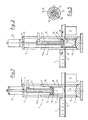
- les figures 1 et 2 montrent des vues en élévation d'une ocupe verticale axiale à travers un premier mode de réalisation du dispositif de formage,
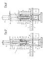
- les figures 3 et 4 montrent des vues en élévation d'une coupe verticale axiale à travers un deuxième mode de réalisation dudit dispositif et
- la figure 5 est une vue en plan d'une coupe horizontale à travers le poinçon de formage selon la ligne V-V des figures 2 et 4.
- FIGS. 1 and 2 show elevation views of an axial vertical eye through a first embodiment of the forming device,
- Figures 3 and 4 show elevational views of a axial vertical section through a second embodiment of said device and
- FIG. 5 is a plan view of a horizontal section through the forming punch along the line VV of FIGS. 2 and 4.
Le dispositif de formage 1 d'articles creux ou de récipients 2, tel que représenté sur le dessin permet de thermoformer lesdits récipients 2 à partir d'une bande thermoplastique 3 dont le trajet est horizontal. Ce dispositif de formage 1 fait, en général, partie d'une installation de conditionnement de type connu, par exemple, par le brevet français FR 2 028 765 ou par la demande de brevet allemand DE-OS 2 754 816 et est placé immédiatement en aval d'un dispositif de chauffage 4 de la bande thermoplastique 2 avançant pas à pas sous le dispositif de chauffage 4 où elle est portée à la température de thermoformage, et à travers le dispositif de formage 1.The device 1 for forming hollow articles or
Le dispositif de formage 1 comprend, en dessous du trajet horizontal de la bande thermoplastique 3, un bloc de moule 5 qui est verticalement mobile entre une position haute de thermoformage représentée sur le dessin et une position basse de démoulage non représentée dans laquelle le récipient 2 qui vient d'être thermoformé et démoulé peut être avancé d'un pas et un nouveau tronçon de bande thermoplastique peut être introduit dans le dispositif de formage 1, l'extrémité supérieure du bloc de moule 5 se trouvant en dessous du fond du récipient 2. Ce bloc de moule 5 comporte au moins une chambre de formage 6 ouverte à son extrémité supérieure et présentant une conformation intérieure identique à la forme extérieure du récipient 2 à thermoformer, étant entendu que l'ouverture de ladite chambre 6 possède une section transversale suffisante pour permettre le démoulage dudit récipient 2. Des orifices d'évacuation d'air 7 sont ménagés dans le bloc de moule 5, débouchant dans le fond de la chambre de formage 6 et reliant celle-ci à l'atmosphère ou à une pompe à vide.The forming device 1 comprises, below the horizontal path of the
Le dispositif de formage 1 comprend, en outre, au-dessus du trajet horizontal de la bande thermoplastique 3, un bloc de contre-moule 8 qui est soit en position fixe, soit mobile verticalement sur une faible distance entre, d'une part, une position basse représentée sur le dessin, dans laquelle il est en contact avec la bande thermoplastique 3 et, en position haute du bloc de moule 5, serre celle-ci contre le bord supérieur de chaque chambre de formage 6, et, d'autre part, une position haute légèrement écartée du trajet horizontal de la bande thermoplastique pour faciliter l'avancement de celle-ci. Le bloc de contre-moule 8 est muni d'autant de cavités cylindriques 9 que le bloc de moule 5 possède de chambre de formage 6, ces cavités 9 étant disposées coaxialement aux chambres de formage 6. Selon le premier mode de réalisation représenté sur les figures 1 et 2, ces cavités cylindriques 9 sont ouvertes aux deux extrémités. Dans chaque cavité cylindrique 9 est monté un poinçon de formage 10 qui est coaxial à ladite cavité 9 et à la chambre de formage correspondante 6 et qui est verticalement mobile, par exemple, sous l'action d'une tige de commande 11 faisant partie d'un vérin de commande 12 monté sur un bâti extérieur 13. Le poinçon de formage 10 présente une partie supérieure dite inactive puisqu'elle ne participe pas directement au formage du récipient 2 ainsi qu'une partie inférieure dite active puisqu'elle participe au formage dudit récipient 2. Il est à noter que la partie supérieure inactive du poinçon de formage 10 reste toujours à l'intérieur de la cavité cylindrique 9 et en dehors de la chambre de formage 6 tandis que la partie inférieure active dudit poinçon 10 est susceptible de pénétrer verticalement dans la chambre de formage 6 et de pousser la zone de bande thermoplastique enserrée sur son bord entre le bloc de moule 5 et le bloc de contre-moule 8 autour de l'ouverture supérieure de ladite chambre 6 (voir figures 2 et 4). La partie inactive du poinçon de formage 10 présente une section transversale inférieure à celle de la cavité cylindrique 9 et la partie active dudit poinçon 10 possède des dimensions similaires mais aussi inférieures à celles de la chambre de formage correspondante 6.The forming device 1 further comprises, above the horizontal path of the
Comme on peut le voir sur le dessin, il existe entre le pourtour du poinçon de formage 10 et la cavité cylindrique 9 et la chambre de formage 6 un certain jeu latéral. Un espace annulaire 14 est délimité dans chaque cavité cylindrique 9 par la face intérieure de celle-ci et par la face périphérique dudit poinçon 10. Chaque poinçon de formage 10, et plus précisément dit la partie inactive supérieure de celui-ci, est surmonté d'un piston de guidage 15 qui obture de façon étanche l'extrémité supérieure de l'espace annulaire 14 et dont la section transversale est plus grande que celle du poinçon 10 et adaptée à celle de la cavité cylindrique pour permettre audit piston 15 d'y coulisser de façon étanche sous l'action du vérin de commande 12 et de sa tige 11 dont l'extrémité inférieure est solidaire dudit piston 15. L'espace annulaire 14 est raccordé périodiquement à une source de gaz comprimé tel que de l'air comprimé, le cas échéant stérile, à l'aide d'au moins un conduit de liaison 16 débouchant dans l'espace annulaire 14 soit près de l'extrémité inférieure du bloc de contre-moule 8, soit au niveau de l'extrémité supérieure du poinçon de formage 10. Une soupape de commande non représentée est interposée dans le circuit d'alimentation en gaz comprimé, le cas échéant stérile, entre le conduit de liaison 16 et la source de gaz comprimé.As can be seen in the drawing, there is between the around the forming
La partie supérieure inactive du poinçon de formage 10 présente une hauteur axiale inférieure à la largeur maximale dudit poinçon 10 et de préférence est assez faible mais suffisante pour que le piston de guidage 15 reste suffisamment écarté du trajet de la bande thermoplastique 3 en position basse du poinçon de formage 10. Avantageusement, la hauteur axiale de la partie supérieure inactive du poinçon de formage 10 est comprise entre un dixième et cinq dixièmes de la largeur maximale dudit poinçon 10.The inactive upper part of the forming
Le ou les conduits de liaison 16 peuvent être ménagés dans le piston de guidage 15 près de la périphérie de ce dernier de façon à présenter des axes parallèles à celui du piston 15 et du poinçon 10 et à déboucher directement dans l'extrémité supérieure de l'espace annulaire 14. Dans certains cas, il peut être avantageux de ménager le ou les conduits de liaison 16 dans la paroi latérale du bloc de contre-moule 8 de sorte que ces conduits débouchent soit radialement soit obliquement dans l'espace annulaire 14 près de l'extrémité inférieure dudit bloc 8, les axes des embouchures de ces conduits 16 étant situés de préférence dans un plan perpendiculaire à l'axe du poinçon 10 et du piston 15.The connection duct (s) 16 may be formed in the
La tige de commande 11 dont l'extrémité inférieure est fixée coaxialement au poinçon de formage 10 sur le côté du piston de guidage 15, opposé audit poinçon 10, présente sur son tronçon inférieur d'une longueur légèrement supérieure à la hauteur de la cavité cylindrique 9 ou à celle de l'ensemble poinçon 10-piston 15, un canal coaxial 17 qui, à son extrémité supérieure, située en dehors de la cavité cylindrique 9, est raccordé alternativement à l'atmosphère ou à une source d'air comprimé par l'intermédiaire d'une soupape non représentée. Dans ce cas, le conduit de liaison 16 ménagé dans le piston de guidage 15 est aligné avec le canal coaxial 17, pénètre sur une faible hauteur dans la partie inactive du poinçon de formage 10 et est raccordé, d'une part, à l'extrémité inférieure du canal coaxial 17 et, d'autre part, aux extrémités centrales d'une pluralité de canaux radiaux 18 ménagés horizontalement dans la partie inactive du poinçon de formage 10 et débouchant au voisinage de la face inférieure du piston 15 sur la face périphérique du poinçon de formage 10.The
Il est à remarquer que dans la mesure où les jets de gaz comprimé sont envoyés dans l'espace annulaire 14 soit dans un plan perpendiculaire à l'axe du poinçon de formage 10 et du piston 15, soit suivant des directions faiblement inclinées par rapport à ce plan, ces jets se brisent d'abord à l'intérieur de l'espace annulaire 14 soit contre la face intérieure de la cavité cylindrique 9, soit contre le pourtour du poinçon 10 avant d'être déviés vers la zone enserrée de bande thermoplastique 3a et l'intérieur de la chambre de formage 6. On évite ainsi avec certitude que des jets d'air comprimé soient dirigés directement contre la bande thermoplastique et percent celle-ci.It should be noted that insofar as the jets of compressed gas are sent into the
Le dispositif de formage 1 peut également être utilisé de façon avantageuse dans le cadre d'une installation de conditionnement stérile de produits stériles ou stérilisés, notamment dans une installation du type connu par la demande de brevet allemand DT-OS 2 754 816. A cet effet, l'extrémité inférieure du bloc de contre-moule 8 est montée de façon étanche sur le tunnel stérile 19 d'une installation de conditionnement, tunnel 19 dont les parois verticales latérales coopèrent avec les bords latéraux de la bande thermoplastique 3 de façon à éviter une fuite trop importante du gaz stérile en légère surpression remplissant le volume délimité par ledit tunnel 19. L'extrémité inférieure du bloc de contre-moule 8 pénètre de façon étanche dans le tunnel stérile 19. La cavité cylindrique 9 du bloc de contre-moule 8 est fermée, à son extrémité supérieure, par un couvercle 20 muni d'une ouverture centrale 21 dans laquelle est guidé le tronçon inférieur 11a de la tige de commande 11. A l'intérieur de la cavité cylindrique 9, c'est-à-dire, sur sa partie pénétrant à l'intérieur de ladite cavité 9, le tronçon inférieur 11a est entouré de façon étanche d'un soufflet de protection 22 qui s'étend à partir du couvercle 20 soit jusqu'au piston de guidage 15 soit jusqu'à un endroit du tronçon inférieur 11a proche dudit piston 15. L'extrémité inférieure du soufflet de protection 22 est fixée de façon étanche soit sur le piston 15, soit sur le tronçon inférieur 11a de la tige de commande 11 à proximité dudit piston 15. L'extrémité supérieure du soufflet de protection 22 est fixée de façon étanche sur le couvercle 20 autour de l'ouverture centrale 21 de celui-ci ou bien est montée en tant que joint d'étanchéité entre l'extrémité supérieure du bloc de contre-moule 8 et la face inférieure du couvercle 20. La structure du soufflet 22 est d'un type connu qui peut comporter à l'intérieur de chaque pli de soufflet 22a une rondelle de rigidification 22b entourant le tronçon inférieur 11a de façon à pouvoir coulisser librement le long de celui-ci. Le volume annulaire variable 23 entouré par le soufflet 22 et délimité pour l'essentiel par la face inférieure du couvercle 20, la face intérieure du soufflet 22 et la partie du tronçon inférieur 11a pénétrant dans la cavité cylindrique 9 et, le cas échéant, par une partie de la face supérieure du piston de guidage 15 est relié en permanence à l'atmosphère par l'ouverture centrale de guidage 21 du couvercle 20 et/ou par un trou de respiration 24 ménagé dans ledit couvercle 20 à l'intérieur du bord supérieur du soufflet 22. La chambre annulaire 25 prévue à l'intérieur de la cavité cylindrique 9 et délimitée par la face interne de celle-ci, par la face extérieure du soufflet de protection 22, par la face supérieure du piston de guidage 15 et, le cas échéant, par les parties libres du tronçon inférieur 11a logé dans ladite cavité 9, et de la face inférieure du couvercle 20 non recouverte par le soufflet 22, est alimentée en période de service et est remplie en permanence d'un gaz stérile en légère surpression par rapport à la pression atmosphérique, cette alimentation s'effectuant à travers un orifice d'entrée 26 ménagé près du couvercle 20 dans la paroi latérale du bloc de contre-moule 8 et raccordé à un circuit d'alimentation approprié qui permet de maintenir dans cette chambre annulaire 25 une légère surpression sensiblement constante malgré les variations du volume de ladite chambre 25. Il est à noter que dans le cas d'un conditionnement stérile des produits, le ou les conduits de liaison 16, y compris les canaux radiaux 18 débouchant dans l'espace annulaire 14 et le canal coaxial 17, sont raccordés périodiquement, à l'extérieur de la cavité cylindrique 9, à une source de gaz stérile sous pression, par l'intermédiaire d'une soupape de commande non représentée.The forming device 1 can also be used advantageously in the context of a sterile packaging installation for sterile or sterilized products, in particular in an installation of the type known by the German patent application DT-OS 2 754 816. For this purpose, the lower end of the
Afin de faciliter la restérilisation et le nettoyage de la chambre annulaire 25 et de tous les éléments qui la délimitent, celle-ci est susceptible d'être raccordée à un circuit de stérilisation (eau chaude, vapeur d'eau surchauffée à forte pression) à travers, d'une part, l'orifice d'entrée 26 et, d'autre part, un orifice de sortie 27 prévu dans la paroi latérale du bloc de contre-moule 8 à un endroit diamétralement opposé à l'emplacement de l'orifice d'entrée 26 et situé légèrement au-dessus du piston de guidage 15 en position haute dans laquelle le poinçon de formage 10 est logé entièrement à l'intérieur de la cavité cylindrique 9 et les plis annulaires 22a du soufflet 22 sont rapprochés les uns des autres et en contact mutuel (figure 3). Il est avantageux de revêtir le poinçon de formage 10 d'une couche de matière plastique souple à base de silicone. Cette mesure permet au poinçon 10 d'atteindre rapidement et de maintenir une température constante d'une valeur proche ou égale de celle de la bande thermoplastique 3 au moment du thermoformage.In order to facilitate the re-sterilization and cleaning of the
Le procédé de thermoformage d'un récipient thermoplastique 2 à l'aide du dispositif de formage qui vient d'être décrit se comprend de lui-même. Une zone de bande thermoplastique 3a préchauffée à la température de thermoformage est enserrée sur son bord entre, d'une part, l'extrémité supérieure du bloc de moule 5, extrémité entourant l'ouverture de la chambre de formage 6, et, d'autre part, l'extrémité inférieure du bloc de contre-moule 8, extrémité entourant la cavité cylindrique 9 à l'intérieur de laquelle se trouve alors entièrement rétracté le poinçon de formage 10. En raison même de la structure du dispositif, notamment en raison du piston de guidage 15 prévu dans la cavité cylindrique 9 au-dessus du poinçon 10, on ferme hermétiquement l'espace annulaire 14 dès que l'on enserre la zone de bande préchauffée 3a, avant l'opération de thermoformage d'un récipient 2 à partir de cette zone de bande 3a. Le volume de cet espace annulaire 14 varie pendant l'opération de thermoformage lors de la descente du poinçon de formage 10 et l'injection du gaz comprimé. Cet espace annulaire 14 étant hermétiquement fermé pendant toute la course descendante du poinçon de formage 10 au cours de laquelle ce dernier quitte partiellement la cavité cylindrique 9 et pénètre dans la chambre de formage 6 jusqu'au voisinage du fond de celle-ci, on peut y injecter le gaz sous pression dès la fermeture dudit espace 14 et on l'y injecte au plus tard à la fin de la course descendante du piston de formage 10. En conséquence, si certains matériaux composant la bande thermoplastique 3 l'exigent, on peut injecter le gaz sous pression dans l'espace annulaire 14 hermétiquement fermé, déjà pendant la course descendante du poinçon de formage 10. Le gaz comprimé peut être injecté dans l'espace annulaire 14 près de l'extrémité supérieure du poinçon 10 et sous la face inférieure du piston 15 ou encore près de l'extrémité inférieure du bloc de contre-moule 8 à l'intérieur de la cavité cylindrique 9 de ce dernier. Il est avantageux d'injecter le gaz comprimé dans l'espace annulaire 14 sous forme de jets de gaz multiples et de les orienter de telle sorte qu'ils ne frappent pas directement la zone de bande enserrée 3a. A cet effet, on injecte le gaz sous pression sous forme de jets radiaux s'étendant pour l'essentiel dans un plan perpendiculaire à l'axe de la cavité cylindrique 9 à l'intérieur de celle-ci. Dans ce cas, les jets gazeux sont orientés pour l'essentiel perpendiculairement soit à la paroi de la cavité cylindrique 9 et en direction de celle-ci, soit à l'axe de ladite cavité 9 et en direction de celui-ci. Ainsi, les jets gazeux frappent d'abord soit la paroi de la cavité 9 soit le pourtour du poinçon de formage 10 avant d'être détournés vers la chambre de formage 6 et sur la zone de bande enserrée 3a.The process for thermoforming a
L'objet de la présente invention peut subir un certain nombre de modifications à la portée de l'homme de métier sans que l'on sorte du cadre de protection défini par les revendications annexées.The object of the present invention may undergo a number of modifications within the reach of the skilled person without departing from the protective framework defined by the appended claims.
Claims (19)
Applications Claiming Priority (2)
| Application Number | Priority Date | Filing Date | Title |
|---|---|---|---|
| FR9006003 | 1990-05-14 | ||
| FR9006003A FR2661864B1 (en) | 1990-05-14 | 1990-05-14 | DEVICE AND METHOD FOR FORMING HOLLOW ARTICLES OF THERMOPLASTIC MATERIAL. |
Publications (1)
| Publication Number | Publication Date |
|---|---|
| EP0457664A1 true EP0457664A1 (en) | 1991-11-21 |
Family
ID=9396590
Family Applications (1)
| Application Number | Title | Priority Date | Filing Date |
|---|---|---|---|
| EP91401233A Ceased EP0457664A1 (en) | 1990-05-14 | 1991-05-14 | Apparatus and method for moulding hollow articles from thermoplastic materials |
Country Status (5)
| Country | Link |
|---|---|
| EP (1) | EP0457664A1 (en) |
| JP (1) | JPH04229225A (en) |
| AU (1) | AU7700891A (en) |
| CA (1) | CA2042194A1 (en) |
| FR (1) | FR2661864B1 (en) |
Cited By (7)
| Publication number | Priority date | Publication date | Assignee | Title |
|---|---|---|---|---|
| FR2753125A1 (en) * | 1996-09-06 | 1998-03-13 | Theno Jacques | Thermoforming of plastic food containers |
| WO1999044808A1 (en) * | 1998-03-06 | 1999-09-10 | Jacques Theno | Thermoforming method and device, in particular for making a container |
| FR2796039A1 (en) * | 1999-07-09 | 2001-01-12 | Mobile | METHOD FOR THERMOFORMING POTS AND DEVICE FOR IMPLEMENTING SAME |
| DE10220700B4 (en) * | 2002-05-10 | 2004-04-22 | Adolf Illig Maschinenbau Gmbh & Co.Kg | Forming tool for deep-drawing containers made of thermoplastic material |
| DE10211125B4 (en) * | 2002-03-14 | 2004-09-30 | Adolf Illig Maschinenbau Gmbh & Co.Kg | Mold for deep-drawing containers made of thermoplastic |
| CN111894106A (en) * | 2020-08-11 | 2020-11-06 | 安徽兴浩建设有限公司 | Rapid construction method for lightweight template of reinforced concrete cast-in-place circular drainage inspection well |
| CN114749562A (en) * | 2022-06-14 | 2022-07-15 | 成都飞机工业(集团)有限责任公司 | Air guide system of superplastic forming/diffusion bonding die and manufacturing method thereof |
Families Citing this family (1)
| Publication number | Priority date | Publication date | Assignee | Title |
|---|---|---|---|---|
| DE102007050722A1 (en) * | 2007-10-22 | 2009-04-23 | Gabler Thermoform Gmbh & Co. Kg | Method for operating a device for producing molded parts from a thermoplastic plastic film |
Citations (5)
| Publication number | Priority date | Publication date | Assignee | Title |
|---|---|---|---|---|
| US3450807A (en) * | 1967-06-26 | 1969-06-17 | Dow Chemical Co | Thermoplastic sheet formation |
| US3465071A (en) * | 1966-06-08 | 1969-09-02 | Illinois Tool Works | Reduced neck article forming method and apparatus |
| US3483284A (en) * | 1966-03-15 | 1969-12-09 | Monsanto Co | Method of forming plastic articles |
| US3510913A (en) * | 1966-06-08 | 1970-05-12 | Illinois Tool Works | Deep drawn article forming apparatus |
| FR2374217A1 (en) * | 1976-12-15 | 1978-07-13 | Gatrun Anstalt | Sterilised thermoplastic film pack - in which sterilised webs carry sterile main film through heating moulding filling and sealing points |
-
1990
- 1990-05-14 FR FR9006003A patent/FR2661864B1/en not_active Expired - Fee Related
-
1991
- 1991-05-09 CA CA 2042194 patent/CA2042194A1/en not_active Abandoned
- 1991-05-13 AU AU77008/91A patent/AU7700891A/en not_active Abandoned
- 1991-05-14 EP EP91401233A patent/EP0457664A1/en not_active Ceased
- 1991-05-14 JP JP13702391A patent/JPH04229225A/en active Pending
Patent Citations (5)
| Publication number | Priority date | Publication date | Assignee | Title |
|---|---|---|---|---|
| US3483284A (en) * | 1966-03-15 | 1969-12-09 | Monsanto Co | Method of forming plastic articles |
| US3465071A (en) * | 1966-06-08 | 1969-09-02 | Illinois Tool Works | Reduced neck article forming method and apparatus |
| US3510913A (en) * | 1966-06-08 | 1970-05-12 | Illinois Tool Works | Deep drawn article forming apparatus |
| US3450807A (en) * | 1967-06-26 | 1969-06-17 | Dow Chemical Co | Thermoplastic sheet formation |
| FR2374217A1 (en) * | 1976-12-15 | 1978-07-13 | Gatrun Anstalt | Sterilised thermoplastic film pack - in which sterilised webs carry sterile main film through heating moulding filling and sealing points |
Cited By (9)
| Publication number | Priority date | Publication date | Assignee | Title |
|---|---|---|---|---|
| FR2753125A1 (en) * | 1996-09-06 | 1998-03-13 | Theno Jacques | Thermoforming of plastic food containers |
| WO1999044808A1 (en) * | 1998-03-06 | 1999-09-10 | Jacques Theno | Thermoforming method and device, in particular for making a container |
| FR2796039A1 (en) * | 1999-07-09 | 2001-01-12 | Mobile | METHOD FOR THERMOFORMING POTS AND DEVICE FOR IMPLEMENTING SAME |
| DE10211125B4 (en) * | 2002-03-14 | 2004-09-30 | Adolf Illig Maschinenbau Gmbh & Co.Kg | Mold for deep-drawing containers made of thermoplastic |
| DE10220700B4 (en) * | 2002-05-10 | 2004-04-22 | Adolf Illig Maschinenbau Gmbh & Co.Kg | Forming tool for deep-drawing containers made of thermoplastic material |
| CN111894106A (en) * | 2020-08-11 | 2020-11-06 | 安徽兴浩建设有限公司 | Rapid construction method for lightweight template of reinforced concrete cast-in-place circular drainage inspection well |
| CN111894106B (en) * | 2020-08-11 | 2021-07-20 | 安徽兴浩建设有限公司 | Rapid construction method for lightweight template of reinforced concrete cast-in-place circular drainage inspection well |
| CN114749562A (en) * | 2022-06-14 | 2022-07-15 | 成都飞机工业(集团)有限责任公司 | Air guide system of superplastic forming/diffusion bonding die and manufacturing method thereof |
| CN114749562B (en) * | 2022-06-14 | 2022-10-25 | 成都飞机工业(集团)有限责任公司 | Air guide system of superplastic forming/diffusion connecting die and manufacturing method thereof |
Also Published As
| Publication number | Publication date |
|---|---|
| FR2661864A1 (en) | 1991-11-15 |
| CA2042194A1 (en) | 1991-11-15 |
| AU7700891A (en) | 1991-11-14 |
| FR2661864B1 (en) | 1994-10-07 |
| JPH04229225A (en) | 1992-08-18 |
Similar Documents
| Publication | Publication Date | Title |
|---|---|---|
| EP2595792B1 (en) | Method of forming a container by blowing and filling | |
| CA2293843C (en) | Nozzle for blow moulding plastic containers and installation provided with same | |
| EP2170580A1 (en) | Installation for the manufacture of containers from a preform and method of controlling the blow-moulding means of such an installation | |
| FR2511973A1 (en) | ||
| EP0457664A1 (en) | Apparatus and method for moulding hollow articles from thermoplastic materials | |
| EP0369888A1 (en) | Method and device for the sterilization of an installation for packaging foodstuffs or pharmaceutical products | |
| EP1915295B1 (en) | Low-speed inerting means and device for using said inerting means for packaging a food product | |
| FR2604243A1 (en) | METHOD FOR MANUFACTURING A COLD-ACCUMULATING MASS FROM CARBONIC ANHYDRIDE AND ACCUMULATOR OBTAINED | |
| CH621739A5 (en) | ||
| EP1432616B1 (en) | Device for packaging products under controlled atmosphere | |
| CH366924A (en) | Process for manufacturing and filling capsules of heat-sealable material and device for implementing the process | |
| EP1066142B1 (en) | Facility for producing latex objects such as pillows | |
| FR2525559A1 (en) | METHOD AND DEVICE FOR THE PRODUCTION OF A PACKAGING | |
| CH426236A (en) | Process for the manufacture of a container provided with an outer coating, extrusion apparatus for carrying out this process, and container obtained by this process | |
| EP0069007B1 (en) | Method of producing blow-stretched plastics containers, and apparatus for carrying out the method | |
| CH678416A5 (en) | ||
| FR2851227A1 (en) | Plastic bottle forming, filling and sealing process and plant uses plastic strip shaped round blowing/filling tube, molded into bottles and sealed after filling | |
| EP0493197B1 (en) | Process for molding a liquefiable material, especially soaps, and transparent or translucent soaps | |
| EP3573891B1 (en) | Method for manufacturing a device for dispensing a product | |
| EP1063077A1 (en) | Process for producing of conditioned articles and apparatus for producing the same | |
| CH345260A (en) | Process for placing a previously sterilized product in sterile containers under sterile conditions and installation for carrying out the process | |
| FR2763561A1 (en) | STERILE INFLATION SYSTEM FOR A CLOSED FLEXIBLE WALL BAG | |
| FR2597833A1 (en) | Method and device for heat-sealing trays with gaseous internal atmosphere | |
| EP0734971B1 (en) | Thermoformed plastic container, e.g. for food products, and apparatus for its manufacture | |
| FR2722135A1 (en) | Device for thermo-forming plastic containers |
Legal Events
| Date | Code | Title | Description |
|---|---|---|---|
| PUAI | Public reference made under article 153(3) epc to a published international application that has entered the european phase |
Free format text: ORIGINAL CODE: 0009012 |
|
| AK | Designated contracting states |
Kind code of ref document: A1 Designated state(s): CH DE ES FR GB IT LI |
|
| 17P | Request for examination filed |
Effective date: 19920217 |
|
| RAP1 | Party data changed (applicant data changed or rights of an application transferred) |
Owner name: JAGENBERG AKTIENGESELLSCHAFT |
|
| 17Q | First examination report despatched |
Effective date: 19930813 |
|
| 111L | Licence recorded |
Free format text: 0100 E.R.C.A. (ETUDE ET REALISATION DE CHAINES AUTOMATIQUES),S.A. |
|
| STAA | Information on the status of an ep patent application or granted ep patent |
Free format text: STATUS: THE APPLICATION HAS BEEN REFUSED |
|
| 18R | Application refused |
Effective date: 19950608 |