EP0457538A1 - Method for coating an article - Google Patents
Method for coating an article Download PDFInfo
- Publication number
- EP0457538A1 EP0457538A1 EP91304291A EP91304291A EP0457538A1 EP 0457538 A1 EP0457538 A1 EP 0457538A1 EP 91304291 A EP91304291 A EP 91304291A EP 91304291 A EP91304291 A EP 91304291A EP 0457538 A1 EP0457538 A1 EP 0457538A1
- Authority
- EP
- European Patent Office
- Prior art keywords
- shield
- coating
- gas
- shielding means
- shielded
- Prior art date
- Legal status (The legal status is an assumption and is not a legal conclusion. Google has not performed a legal analysis and makes no representation as to the accuracy of the status listed.)
- Granted
Links
Images
Classifications
-
- C—CHEMISTRY; METALLURGY
- C23—COATING METALLIC MATERIAL; COATING MATERIAL WITH METALLIC MATERIAL; CHEMICAL SURFACE TREATMENT; DIFFUSION TREATMENT OF METALLIC MATERIAL; COATING BY VACUUM EVAPORATION, BY SPUTTERING, BY ION IMPLANTATION OR BY CHEMICAL VAPOUR DEPOSITION, IN GENERAL; INHIBITING CORROSION OF METALLIC MATERIAL OR INCRUSTATION IN GENERAL
- C23C—COATING METALLIC MATERIAL; COATING MATERIAL WITH METALLIC MATERIAL; SURFACE TREATMENT OF METALLIC MATERIAL BY DIFFUSION INTO THE SURFACE, BY CHEMICAL CONVERSION OR SUBSTITUTION; COATING BY VACUUM EVAPORATION, BY SPUTTERING, BY ION IMPLANTATION OR BY CHEMICAL VAPOUR DEPOSITION, IN GENERAL
- C23C16/00—Chemical coating by decomposition of gaseous compounds, without leaving reaction products of surface material in the coating, i.e. chemical vapour deposition [CVD] processes
- C23C16/06—Chemical coating by decomposition of gaseous compounds, without leaving reaction products of surface material in the coating, i.e. chemical vapour deposition [CVD] processes characterised by the deposition of metallic material
- C23C16/08—Chemical coating by decomposition of gaseous compounds, without leaving reaction products of surface material in the coating, i.e. chemical vapour deposition [CVD] processes characterised by the deposition of metallic material from metal halides
-
- C—CHEMISTRY; METALLURGY
- C23—COATING METALLIC MATERIAL; COATING MATERIAL WITH METALLIC MATERIAL; CHEMICAL SURFACE TREATMENT; DIFFUSION TREATMENT OF METALLIC MATERIAL; COATING BY VACUUM EVAPORATION, BY SPUTTERING, BY ION IMPLANTATION OR BY CHEMICAL VAPOUR DEPOSITION, IN GENERAL; INHIBITING CORROSION OF METALLIC MATERIAL OR INCRUSTATION IN GENERAL
- C23C—COATING METALLIC MATERIAL; COATING MATERIAL WITH METALLIC MATERIAL; SURFACE TREATMENT OF METALLIC MATERIAL BY DIFFUSION INTO THE SURFACE, BY CHEMICAL CONVERSION OR SUBSTITUTION; COATING BY VACUUM EVAPORATION, BY SPUTTERING, BY ION IMPLANTATION OR BY CHEMICAL VAPOUR DEPOSITION, IN GENERAL
- C23C10/00—Solid state diffusion of only metal elements or silicon into metallic material surfaces
- C23C10/04—Diffusion into selected surface areas, e.g. using masks
Definitions
- the present invention relates to coating articles, and more particularly, to an apparatus and method for producing gas phase deposition metallic coatings of variable thickness.
- the aluminizing process is well known for improving the oxidation and corrosion resistance of many substrates such as alloys containing chromium, iron, nickel, or cobalt, as the major constituent.
- aluminide coatings are known to improve the oxidation and corrosion resistance properties of the nickel-and-cobalt-based superalloys which are used in high-temperature environments, such as gas turbine blades and vanes.
- the article to be coated is embedded in a powder pack containing powdered aluminum, either as the metal, an alloy; or a compound such as with cobalt, a carrier, typically an ammonium or alkali metal halide, and an inert filler such as aluminum oxide.
- a carrier typically an ammonium or alkali metal halide
- an inert filler such as aluminum oxide.
- the article is heated to between 1400°F (760°C) and 2200°F (1204°C) depending on the particular coating material, with the thickness of the coating depending on the temperature and the duration of the exposure.
- the halide acts as a carrier or activator to facilitate the transfer of the aluminum from the powder pack to the exposed surface of the article, where the aluminum is deposited.
- the aluminum and the substrate material interdiffuse to form an aluminide coating, and the halide is freed to transport more aluminum from the powder pack to the article.
- the coating thickness increases, the interdiffusion of the aluminum and the substrate decreases, thereby increasing the percent by weight of aluminum in the aluminide coating.
- the out-of-pack process is very useful in applying aluminide coatings to the airfoil section of gas turbine blades.
- Turbine blades so coated demonstrate significantly greater oxidation and corrosion resistance than uncoated blades, increasing the useful life of the turbine blade. Since the protection from oxidation and corrosion provided by the aluminide coating is directly related to the thickness of that coating, it is desirable to further increase the thickness of the aluminide coating on the airfoil, where that protection is needed most.
- the aluminide coating in this region becomes susceptible to fracturing during blade use if the coating thickness exceeds a maximum allowable thickness.
- the nature of this fracturing is such that cracks in the coating readily propagate into the substrate of the blade platform itself, reducing the integrity, and therefore the useful life, of the turbine blade.
- the aluminide coating thickness necessary to provide the desired oxidation and corrosion resistance on the airfoil is significantly greater than the maximum allowable coating thickness in the blade platform region adjacent the high pressure side of the airfoil. Since the out-of-pack gas deposition method produces a coating of substantially uniform thickness, the aluminide coating thickness on the airfoil has heretofore been limited by the maximum allowable coating thickness in the blade platform region. Consequently, the oxidation and corrosion resistance of gas turbine blades and vanes of the prior art is significantly less than that which could be obtained if the blade platform coating thickness were not a limiting factor.
- Another object of this invention is to provide an apparatus and method for applying an increased durability metal coating to a turbine blade which does not promote crack formation in the region of the blade platform.
- Another object of this invention is to provide an apparatus and method for coating a turbine blade with a metal coating which is thinner in the blade platform region adjacent the airfoil than the coating on the airfoil.
- the present invention provides a method of producing a coating of variable thickness on an exposed surface of an article, said method comprising: providing shielding means for partially shielding a portion of said exposed surface from a coating-material-bearing gas, said shielding means including an edge which conforms to contours of said exposed surface; securing said shielding means in fixed, spaced, relation to said shielded portion of said exposed surface to define a shielded region therebetween and a gap between said edge and said exposed surface; and circulating said gas into contact with said shielded portion and the unshielded portion of said exposed surface to provide said coating thereon; said circulation of said gas into said shielded region being restricted by said shielding means so that said coating is thinner on said shielded portion than on said unshielded portion.
- the present invention provides shielding means for use in producing a coating of variable thickness on an exposed surface of an article by exposing said surface to a gas bearing a coating material
- said shielding means comprising: a shield adapted to be fixed in position adjacent and in spaced relation to a portion of said surface to define a shielded region between said portion and said shield, said shield having an edge which in use is spaced from and conforms to contours of said exposed surface to define a gap therebetween and to partially shield said portion of said surface from said gas; said shield restricting the circulation of said gas into said shielded region so that said gas deposits a thinner coating of said coating material on said shielded portion than on an unshielded portion of said exposed surface.
- the shielding means may be provided for use in coating articles with oxidation and/or corrosion resistant metals such as aluminum, chromium, and the like, by out-of-pack gas phase deposition.
- the shield restricts circulation of the metal-bearing deposition gas near those shielded surfaces of an article which are shielded by the shield, resulting in a thinner coating on those surfaces. Unshielded surfaces can thereby be coated to the desired thickness while the thickness of the shielded surfaces remains at or below the maximum allowable thickness.
- the present invention may be used to coat a gas turbine blade by extending the airfoil section through an aperture in the shield, the aperture being only slightly larger than the outer dimensions of the airfoil, and securing the shield in spaced, proximate relation to the blade platform.
- the turbine blade is exposed to the circulating metal-bearing gas until a coating of the desired thickness builds up on the airfoil. Since the shield restricts circulation of the metal-bearing gas in the blade platform region, the coating on the platform is significantly thinner and more ductile than the coating on the airfoil.
- variable thickness coating exhibits the desired oxidation and/or corrosion resistance on the airfoil while providing the ductility necessary on the blade platform region to avoid crack formation therein.
- a turbine blade may be coated with an aluminum coating so that the aluminum content in the blade platform region is significantly less than the aluminum content of the coating on the airfoil.
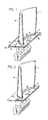
- Fig. 1 Shown in Fig. 1 is a turbine blade 1 with a shield 2 in accordance with the invention attached thereto.
- the shield 2 is preferably constructed of a 0.025 inch (0.64 mm) thick sheet of Hastelloy X, a trademark of Union Carbide Corporation, Danbury, Connecticut, for an alloy containing by weight approximately 48.3% nickel, 22.0% chromium, 1.5% cobalt, 0.10% carbon, 18.5% iron, 9.0% molybdenum, and 0.6% tungsten.
- Hastelloy X is the preferred material for construction of the shield 2, it will be apparent to those skilled in the art that other materials which can withstand the gas phase deposition temperatures may be used as well.
- the shield 2 includes an aperture 3 through which the airfoil section 4 of the turbine blade 1 extends.
- the edge 5 of the shield 2 is shaped to conform to the contours of the airfoil surface 6.
- the aperture 3 is slightly larger than is necessary to receive the airfoil 4, and the airfoil 4 is centered within the aperture 3 so that the edge 5 of the aperture 3 is in spaced relation to the airfoil surface 6.
- a gap 7 is thus defined between the airfoil surface 6 and the edge 5 of the aperture 3, the gap 7 being substantially uniform along the length of the edge 5.
- the shield 2 is secured in fixed, spaced relation to the platform surface 8, so that the separation 9 between the shielded portion of the platform surface 8 and the shield 2 is approximately 0.022 inches (0.56 mm). Although a separation 9 of 0.022 inches is preferred for the present example, a larger or smaller separation 9 may be used depending on whether a thicker or thinner coating, respectively, is desired. As those skilled in the art will readily appreciate, since the percent by weight of aluminum increases with increasing aluminide coating thickness, increasing the separation 9 increases the percent by weight of aluminum in the aluminide coating on that portion of the turbine blade 1 shielded by the shield 2.
- the shield 2 is preferably tack welded to edges 10 of the platform 11 which will eventually be machined off.
- the shield 2 may be secured to any structure which can support the shield in fixed relation to the platform surface 8.
- holes 13 approximately 0.025 inches (0.64 mm) in diameter may be strategically placed in the shield 2 to prevent bare spots in the coating on the platform surface 8 due to excessive shielding.
- FIG. 1 shows an embodiment of the shield 2 of the present invention which shields only the high pressure side of blade platform, leaving the low pressure side of the blade platform exposed. This embodiment is similar to the embodiment shown in Fig. 1, except that the low pressure side of the shield has been removed. Those skilled in the art will recognize that the embodiment shown in Fig.
- the shield 2 may be formed by cutting a blank of Hastelloy X to form an aperture 3 nearly the shape of the airfoil surface 6 contours, and drilling the holes 13. The blank may then be stamped by known sheet metal processes to form the final shape of the shield 2. A shim of 0.022 inches (0.56 mm) may then be placed on the platform surface 8 between the shield 2 and the platform surface 8 to provide the desired separation 9. With the shim in place, the shield 9 may be tack welded to at least one edge 10 of the platform 11, and the shim removed.
- the shield 2 may be made by casting, or any other appropriate metal-forming process known in the art.
- the shield 2 may be part of a reusable mechanical mask which is secured to the turbine blade 1 by means which do not require the destruction of the shield 2 after one use. Once the shield 2 is secured in fixed relation to the turbine blade 1, both may be placed in a coating apparatus heated in excess of 1700°F (927°C), and aluminum deposition gas circulated therein.
- the aluminide coating on a turbine blade is 0.5 to 1.2 mils (0.01 to 0.03 mm) thinner on the shielded section of the platform 11 than on the unshielded portions of the turbine blade which have an aluminide coating thickness of 3.5 mils (0.09mm).
- the coating on the platform surface 8 has a typical aluminum content of approximately 18% by weight as compared to approximately 23% by weight aluminum content in the airfoil section coating.
- a higher aluminum content equates with a lower level of ductility, and a brittle coating may be more susceptible to cracking. Therefore, lower aluminum content of the thinner platform coating provides the oxidation and corrosion resistance desired on the blade platform, while at the same time providing sufficient ductility to withstand operational stresses without promoting crack growth in the blade platform substrate.
- the shielded portion of the surface may have a minimum aluminum content by weight which is not more than 85% of the maximum aluminum content by weight of the unshielded portion.
Abstract
Description
- The present invention relates to coating articles, and more particularly, to an apparatus and method for producing gas phase deposition metallic coatings of variable thickness.
- The aluminizing process is well known for improving the oxidation and corrosion resistance of many substrates such as alloys containing chromium, iron, nickel, or cobalt, as the major constituent. In particular, aluminide coatings are known to improve the oxidation and corrosion resistance properties of the nickel-and-cobalt-based superalloys which are used in high-temperature environments, such as gas turbine blades and vanes.
- In one typical coating process, the article to be coated is embedded in a powder pack containing powdered aluminum, either as the metal, an alloy; or a compound such as with cobalt, a carrier, typically an ammonium or alkali metal halide, and an inert filler such as aluminum oxide. Once embedded, the article is heated to between 1400°F (760°C) and 2200°F (1204°C) depending on the particular coating material, with the thickness of the coating depending on the temperature and the duration of the exposure. The halide acts as a carrier or activator to facilitate the transfer of the aluminum from the powder pack to the exposed surface of the article, where the aluminum is deposited. At the surface of the article, the aluminum and the substrate material interdiffuse to form an aluminide coating, and the halide is freed to transport more aluminum from the powder pack to the article. As the coating thickness increases, the interdiffusion of the aluminum and the substrate decreases, thereby increasing the percent by weight of aluminum in the aluminide coating.
- Another coating process, referred to as out-of-pack gas phase deposition of aluminized coatings, is described in U.S. Pat. Nos. 3,486,927 and 4,148,275. This process is similar to the powder pack method except that the article is not embedded in the powder pack. Instead, the aluminum-bearing halide gas is circulated from the powder pack using an inert gas, and into contact with the article to effect an aluminum deposition on the exposed surfaces of the article, producing a coating of substantially uniform thickness thereon.
- The out-of-pack process is very useful in applying aluminide coatings to the airfoil section of gas turbine blades. Turbine blades so coated demonstrate significantly greater oxidation and corrosion resistance than uncoated blades, increasing the useful life of the turbine blade. Since the protection from oxidation and corrosion provided by the aluminide coating is directly related to the thickness of that coating, it is desirable to further increase the thickness of the aluminide coating on the airfoil, where that protection is needed most.
- However, as the thickness of the aluminide coating increases, the commensurate increase in the percent by weight of aluminum reduces the ductility of the coating. Due to the highly stressed nature of the turbine blade platform region adjacent the high pressure side of the airfoil, the aluminide coating in this region becomes susceptible to fracturing during blade use if the coating thickness exceeds a maximum allowable thickness. The nature of this fracturing is such that cracks in the coating readily propagate into the substrate of the blade platform itself, reducing the integrity, and therefore the useful life, of the turbine blade.
- Unfortunately, the aluminide coating thickness necessary to provide the desired oxidation and corrosion resistance on the airfoil is significantly greater than the maximum allowable coating thickness in the blade platform region adjacent the high pressure side of the airfoil. Since the out-of-pack gas deposition method produces a coating of substantially uniform thickness, the aluminide coating thickness on the airfoil has heretofore been limited by the maximum allowable coating thickness in the blade platform region. Consequently, the oxidation and corrosion resistance of gas turbine blades and vanes of the prior art is significantly less than that which could be obtained if the blade platform coating thickness were not a limiting factor.
- It is therefore an object of the present invention to provide an apparatus and method for coating an article with a coating of variable thickness.
- Another object of this invention is to provide an apparatus and method for applying an increased durability metal coating to a turbine blade which does not promote crack formation in the region of the blade platform.
- Another object of this invention is to provide an apparatus and method for coating a turbine blade with a metal coating which is thinner in the blade platform region adjacent the airfoil than the coating on the airfoil.
- Viewed from one aspect the present invention provides a method of producing a coating of variable thickness on an exposed surface of an article, said method comprising:
providing shielding means for partially shielding a portion of said exposed surface from a coating-material-bearing gas, said shielding means including an edge which conforms to contours of said exposed surface;
securing said shielding means in fixed, spaced, relation to said shielded portion of said exposed surface to define a shielded region therebetween and a gap between said edge and said exposed surface; and
circulating said gas into contact with said shielded portion and the unshielded portion of said exposed surface to provide said coating thereon;
said circulation of said gas into said shielded region being restricted by said shielding means so that said coating is thinner on said shielded portion than on said unshielded portion. - Viewed from a second aspect, the present invention provides shielding means for use in producing a coating of variable thickness on an exposed surface of an article by exposing said surface to a gas bearing a coating material, said shielding means comprising:
a shield adapted to be fixed in position adjacent and in spaced relation to a portion of said surface to define a shielded region between said portion and said shield, said shield having an edge which in use is spaced from and conforms to contours of said exposed surface to define a gap therebetween and to partially shield said portion of said surface from said gas;
said shield restricting the circulation of said gas into said shielded region so that said gas deposits a thinner coating of said coating material on said shielded portion than on an unshielded portion of said exposed surface. - The shielding means may be provided for use in coating articles with oxidation and/or corrosion resistant metals such as aluminum, chromium, and the like, by out-of-pack gas phase deposition. The shield restricts circulation of the metal-bearing deposition gas near those shielded surfaces of an article which are shielded by the shield, resulting in a thinner coating on those surfaces. Unshielded surfaces can thereby be coated to the desired thickness while the thickness of the shielded surfaces remains at or below the maximum allowable thickness.
- For example, the present invention may be used to coat a gas turbine blade by extending the airfoil section through an aperture in the shield, the aperture being only slightly larger than the outer dimensions of the airfoil, and securing the shield in spaced, proximate relation to the blade platform. During out-of-pack deposition, the turbine blade is exposed to the circulating metal-bearing gas until a coating of the desired thickness builds up on the airfoil. Since the shield restricts circulation of the metal-bearing gas in the blade platform region, the coating on the platform is significantly thinner and more ductile than the coating on the airfoil. The resulting variable thickness coating exhibits the desired oxidation and/or corrosion resistance on the airfoil while providing the ductility necessary on the blade platform region to avoid crack formation therein. Thus, a turbine blade may be coated with an aluminum coating so that the aluminum content in the blade platform region is significantly less than the aluminum content of the coating on the airfoil.
- The foregoing and other features and advantages of the present invention will become more apparent from the following description and accompanying drawings of an embodiment given by way of example only.
- Figure 1 is a perspective view of a turbine blade with a shield device according to a first embodiment of the present invention attached; and
- Figure 2 is a perspective view of a turbine blade with a shield according to an alterative embodiment of the present invention attached;
- Shown in Fig. 1 is a turbine blade 1 with a
shield 2 in accordance with the invention attached thereto. Theshield 2 is preferably constructed of a 0.025 inch (0.64 mm) thick sheet of Hastelloy X, a trademark of Union Carbide Corporation, Danbury, Connecticut, for an alloy containing by weight approximately 48.3% nickel, 22.0% chromium, 1.5% cobalt, 0.10% carbon, 18.5% iron, 9.0% molybdenum, and 0.6% tungsten. Although Hastelloy X is the preferred material for construction of theshield 2, it will be apparent to those skilled in the art that other materials which can withstand the gas phase deposition temperatures may be used as well. Theshield 2 includes an aperture 3 through which theairfoil section 4 of the turbine blade 1 extends. Theedge 5 of theshield 2 is shaped to conform to the contours of theairfoil surface 6. The aperture 3 is slightly larger than is necessary to receive theairfoil 4, and theairfoil 4 is centered within the aperture 3 so that theedge 5 of the aperture 3 is in spaced relation to theairfoil surface 6. A gap 7 is thus defined between theairfoil surface 6 and theedge 5 of the aperture 3, the gap 7 being substantially uniform along the length of theedge 5. - The
shield 2 is secured in fixed, spaced relation to the platform surface 8, so that the separation 9 between the shielded portion of the platform surface 8 and theshield 2 is approximately 0.022 inches (0.56 mm). Although a separation 9 of 0.022 inches is preferred for the present example, a larger or smaller separation 9 may be used depending on whether a thicker or thinner coating, respectively, is desired. As those skilled in the art will readily appreciate, since the percent by weight of aluminum increases with increasing aluminide coating thickness, increasing the separation 9 increases the percent by weight of aluminum in the aluminide coating on that portion of the turbine blade 1 shielded by theshield 2. - To secure the
shield 2 in fixed relation to the turbine blade 1, theshield 2 is preferably tack welded toedges 10 of the platform 11 which will eventually be machined off. However, theshield 2 may be secured to any structure which can support the shield in fixed relation to the platform surface 8. Additionally,holes 13 approximately 0.025 inches (0.64 mm) in diameter may be strategically placed in theshield 2 to prevent bare spots in the coating on the platform surface 8 due to excessive shielding. - Although the
shield 2 as shown in Fig. 1 shields substantially all of the blade platform surface, it may be desirable to provide a reduced thickness coating on only the high pressure side of the blade platform. Fig. 2 shows an embodiment of theshield 2 of the present invention which shields only the high pressure side of blade platform, leaving the low pressure side of the blade platform exposed. This embodiment is similar to the embodiment shown in Fig. 1, except that the low pressure side of the shield has been removed. Those skilled in the art will recognize that the embodiment shown in Fig. 1 could be modified to include perforations on the low pressure side of theshield 2, or the gap 7 between the edge 3 and the low pressure side of theairfoil surface 6 could be substantially increased, either of which would reduce the shielding effect of the low pressure side of theshield 2, producing a thicker coating thereon. - The
shield 2 may be formed by cutting a blank of Hastelloy X to form an aperture 3 nearly the shape of theairfoil surface 6 contours, and drilling theholes 13. The blank may then be stamped by known sheet metal processes to form the final shape of theshield 2. A shim of 0.022 inches (0.56 mm) may then be placed on the platform surface 8 between theshield 2 and the platform surface 8 to provide the desired separation 9. With the shim in place, the shield 9 may be tack welded to at least oneedge 10 of the platform 11, and the shim removed. - Alternatively, the
shield 2 may be made by casting, or any other appropriate metal-forming process known in the art. Likewise, theshield 2 may be part of a reusable mechanical mask which is secured to the turbine blade 1 by means which do not require the destruction of theshield 2 after one use. Once theshield 2 is secured in fixed relation to the turbine blade 1, both may be placed in a coating apparatus heated in excess of 1700°F (927°C), and aluminum deposition gas circulated therein. - Test results show that the aluminide coating on a turbine blade is 0.5 to 1.2 mils (0.01 to 0.03 mm) thinner on the shielded section of the platform 11 than on the unshielded portions of the turbine blade which have an aluminide coating thickness of 3.5 mils (0.09mm). In addition to being significantly thinner than the coating on the
airfoil 4, the coating on the platform surface 8 has a typical aluminum content of approximately 18% by weight as compared to approximately 23% by weight aluminum content in the airfoil section coating. As with many aluminides, a higher aluminum content equates with a lower level of ductility, and a brittle coating may be more susceptible to cracking. Therefore, lower aluminum content of the thinner platform coating provides the oxidation and corrosion resistance desired on the blade platform, while at the same time providing sufficient ductility to withstand operational stresses without promoting crack growth in the blade platform substrate. - The shielded portion of the surface may have a minimum aluminum content by weight which is not more than 85% of the maximum aluminum content by weight of the unshielded portion.
- Although this invention has been shown and described with respect to detailed embodiments thereof, it will be understood by those skilled in the art that various changes in form and detail thereof may be made without departing from the scope of the claimed invention.
Claims (16)
- A method of producing a coating of variable thickness on an exposed surface of an article, said method comprising:
providing shielding means for partially shielding a portion of said exposed surface from a coating-material-bearing gas, said shielding means including an edge which conforms to contours of said exposed surface;
securing said shielding means in fixed, spaced, relation to said shielded portion of said exposed surface to define a shielded region therebetween and a gap between said edge and said exposed surface; and
circulating said gas into contact with said shielded portion and the unshielded portion of said exposed surface to provide said coating thereon;
said circulation of said gas into said shielded region being restricted by said shielding means so that said coating is thinner on said shielded portion than on said unshielded portion. - The method of claim 1, wherein the step of securing the shielding means includes the step of securing said shielding means to said article prior to circulating said gas into said shielded region.
- The method of claim 1 or 2, wherein said coating is metallic and said gas is a metal-bearing gas.
- The method of claim 3, further comprising using aluminum bearing gas and spacing said shield from said shielded portion such that the restriction of the circulation of the gas causes the unshielded portion of said coating to have a maximum aluminum content by weight and said shielded portion to have a minimum aluminum content by weight, wherein said minimum aluminum content is not more than 85% of said maximum aluminum content.
- The method of claim 3 or 4, wherein said gas is an aluminum-bearing gas and said shielding means is spaced from said shielded portion a distance sufficient to produce an aluminum content by weight of approximately 23% in said coating on said unshielded portion, and an aluminum content by weight of approximately 18% in said coating on said shielded portion.
- A method of producing a coating of variable thickness on an exposed surface of a turbine blade, said method comprising:
providing a shield means for partially shielding a portion of said exposed surface from a metal-bearing gas, said shield means including an edge which conforms to contours of said exposed surface;
securing said shield means in fixed and spaced relation to said shielded portion of said exposed surface to define a shielded region therebetween and a gap between said edge and said exposed surface;
placing said turbine blade into a coating apparatus;
heating said turbine blade in said coating apparatus to a temperature in excess of 927°C;
introducing said metal-bearing gas into said coating apparatus; and
circulating said metal-bearing gas into contact with said shielded portion and the unshielded portion to provide a metal coating thereon, whereby circulation of said gas into said shielded region is so restricted that said metal-bearing gas deposits a thinner coating on said shielded portion than on said unshielded portion. - The method of claim 6, wherein the step of securing said shield means comprises securing said shield means to said turbine blade prior to placing said turbine blade in said coating apparatus.
- The method of claim 6 or 7, further comprising using aluminum-bearing gas as the metal-bearing gas, and spacing said shield from said shielded portion a distance sufficient to produce an aluminum content by weight of approximately 23% in said coating on said unshielded portion, and an aluminum content by weight of approximately 18% in said coating on said shielded portion.
- Shielding means for use in producing a coating of variable thickness on an exposed surface of an article by exposing said surface to a gas bearing a coating material, said shielding means comprising:
a shield adapted to be fixed in position adjacent and in spaced relation to a portion of said surface to define a shielded region between said portion and said shield, said shield having an edge which in use is spaced from and conforms to contours of said exposed surface to define a gap therebetween and to partially shield said portion of said surface from said gas;
said shield restricting the circulation of said gas into said shielded region so that said gas deposits a thinner coating of said coating material on said shielded portion than on an unshielded portion of said exposed surface. - The shielding means of claim 9, wherein said shield is adapted to be fixed substantially parallel to said shielded portion of said exposed surface.
- The shielding means of claim 9 or 10, wherein said shield is made of a nickel-based alloy.
- The shielding means of claim 9, 10 or 11, wherein said shielding means is adapted to shield a turbine blade.
- The shielding means according to claim 12, wherein said edge of said shield conforms in use to at least the high pressure side of the airfoil of said blade, and said shield is adapted to shield the high pressure side of the platform of said blade.
- The shielding means according to claim 13, wherein said shielding means is provided with an aperture, the edge of which conforms to the contours of both the high and low pressure sides of said airfoil, said shielding means being adapted to shield substantially the whole of said platform.
- The shielding means of claim 12, 13 or 14, wherein said shield is adapted to be fixed to said turbine blade.
- Shielding means according to any of claims 9 to 15, wherein at least one hole is provided in said shield to allow said gas to pass therethrough.
Applications Claiming Priority (2)
| Application Number | Priority Date | Filing Date | Title |
|---|---|---|---|
| US52394590A | 1990-05-14 | 1990-05-14 | |
| US523945 | 1990-05-14 |
Publications (2)
| Publication Number | Publication Date |
|---|---|
| EP0457538A1 true EP0457538A1 (en) | 1991-11-21 |
| EP0457538B1 EP0457538B1 (en) | 1994-08-03 |
Family
ID=24087068
Family Applications (1)
| Application Number | Title | Priority Date | Filing Date |
|---|---|---|---|
| EP91304291A Expired - Lifetime EP0457538B1 (en) | 1990-05-14 | 1991-05-14 | Method for coating an article |
Country Status (5)
| Country | Link |
|---|---|
| EP (1) | EP0457538B1 (en) |
| JP (1) | JP2942645B2 (en) |
| KR (1) | KR100214897B1 (en) |
| DE (1) | DE69103203T2 (en) |
| IL (1) | IL98057A (en) |
Cited By (6)
| Publication number | Priority date | Publication date | Assignee | Title |
|---|---|---|---|---|
| WO1995027125A1 (en) * | 1994-03-30 | 1995-10-12 | United Technologies Corporation | Turbine shroud segment including a coating layer having varying thickness |
| EP1076158A1 (en) * | 1999-08-11 | 2001-02-14 | General Electric Company | Gas turbine component having location-dependent protective coatings thereon |
| US6332926B1 (en) * | 1999-08-11 | 2001-12-25 | General Electric Company | Apparatus and method for selectively coating internal and external surfaces of an airfoil |
| EP1197574A1 (en) * | 2000-10-10 | 2002-04-17 | United Technologies Corporation | Turbine blade coating tool |
| WO2010048931A1 (en) * | 2008-10-27 | 2010-05-06 | Mtu Aero Engines Gmbh | Apparatus for partial covering of a component zone |
| WO2016087215A1 (en) * | 2014-12-04 | 2016-06-09 | Siemens Aktiengesellschaft | Method for coating a turbine blade |
Families Citing this family (2)
| Publication number | Priority date | Publication date | Assignee | Title |
|---|---|---|---|---|
| DE102004040787A1 (en) * | 2004-08-23 | 2006-03-02 | Heinzl, Joachim, Prof. Dr.-Ing. | Galvanic gold-plating process for turbine blades, ships' masts, drive shafts aircraft wing structures, load-bearing components in buildings and bridges |
| CN103243295B (en) * | 2013-05-16 | 2015-08-05 | 中国电子科技集团公司第四十一研究所 | The method of functional coating is prepared for aluminum alloy surface selectivity |
Citations (2)
| Publication number | Priority date | Publication date | Assignee | Title |
|---|---|---|---|---|
| US3114961A (en) * | 1959-03-20 | 1963-12-24 | Power Jets Res & Dev Ltd | Treatment of porous bodies |
| GB2210387A (en) * | 1987-09-30 | 1989-06-07 | Rolls Royce Plc | Selective chemical vapour deposition |
-
1991
- 1991-05-03 IL IL9805791A patent/IL98057A/en not_active IP Right Cessation
- 1991-05-13 KR KR1019910007649A patent/KR100214897B1/en not_active IP Right Cessation
- 1991-05-13 JP JP3137289A patent/JP2942645B2/en not_active Expired - Fee Related
- 1991-05-14 DE DE69103203T patent/DE69103203T2/en not_active Expired - Fee Related
- 1991-05-14 EP EP91304291A patent/EP0457538B1/en not_active Expired - Lifetime
Patent Citations (2)
| Publication number | Priority date | Publication date | Assignee | Title |
|---|---|---|---|---|
| US3114961A (en) * | 1959-03-20 | 1963-12-24 | Power Jets Res & Dev Ltd | Treatment of porous bodies |
| GB2210387A (en) * | 1987-09-30 | 1989-06-07 | Rolls Royce Plc | Selective chemical vapour deposition |
Non-Patent Citations (1)
| Title |
|---|
| PATENT ABSTRACTS OF JAPAN vol. 9, no. 66 (C-271)(1789) March 26, 1985 & JP-A-59 197 558 (MAZDA ) November 9, 1984 * |
Cited By (9)
| Publication number | Priority date | Publication date | Assignee | Title |
|---|---|---|---|---|
| WO1995027125A1 (en) * | 1994-03-30 | 1995-10-12 | United Technologies Corporation | Turbine shroud segment including a coating layer having varying thickness |
| EP1076158A1 (en) * | 1999-08-11 | 2001-02-14 | General Electric Company | Gas turbine component having location-dependent protective coatings thereon |
| US6296447B1 (en) | 1999-08-11 | 2001-10-02 | General Electric Company | Gas turbine component having location-dependent protective coatings thereon |
| US6332926B1 (en) * | 1999-08-11 | 2001-12-25 | General Electric Company | Apparatus and method for selectively coating internal and external surfaces of an airfoil |
| US6616969B2 (en) | 1999-08-11 | 2003-09-09 | General Electric Company | Apparatus and method for selectively coating internal and external surfaces of an airfoil |
| EP1076111A3 (en) * | 1999-08-11 | 2006-03-22 | General Electric Company | Apparatus and method for selectively coating internal and external surfaces of an airfoil |
| EP1197574A1 (en) * | 2000-10-10 | 2002-04-17 | United Technologies Corporation | Turbine blade coating tool |
| WO2010048931A1 (en) * | 2008-10-27 | 2010-05-06 | Mtu Aero Engines Gmbh | Apparatus for partial covering of a component zone |
| WO2016087215A1 (en) * | 2014-12-04 | 2016-06-09 | Siemens Aktiengesellschaft | Method for coating a turbine blade |
Also Published As
| Publication number | Publication date |
|---|---|
| EP0457538B1 (en) | 1994-08-03 |
| JP2942645B2 (en) | 1999-08-30 |
| DE69103203D1 (en) | 1994-09-08 |
| IL98057A0 (en) | 1992-06-21 |
| DE69103203T2 (en) | 1995-05-04 |
| JPH04228556A (en) | 1992-08-18 |
| KR910020198A (en) | 1991-12-19 |
| KR100214897B1 (en) | 1999-08-02 |
| IL98057A (en) | 1994-11-28 |
Similar Documents
| Publication | Publication Date | Title |
|---|---|---|
| US5225246A (en) | Method for depositing a variable thickness aluminide coating on aircraft turbine blades | |
| US4285459A (en) | High temperature braze repair of superalloys | |
| US5658614A (en) | Platinum aluminide CVD coating method | |
| US5217757A (en) | Method for applying aluminide coatings to superalloys | |
| EP2612951B1 (en) | Method for making a honeycomb seal | |
| US3978251A (en) | Aluminide coatings | |
| USRE31339E (en) | Process for producing elevated temperature corrosion resistant metal articles | |
| EP0491414B1 (en) | Method of forming platinum-silicon-enriched diffused aluminide coating on a superalloy substrate | |
| GB2130249A (en) | Diffusion coating of metals | |
| GB2129017A (en) | Forming protective diffusion layer on nickel cobalt and iron base alloys | |
| US6605364B1 (en) | Coating article and method for repairing a coated surface | |
| JPH108236A (en) | High temperature alloy article coated with discrete additional protective coating and its production | |
| US3904789A (en) | Masking method for use in aluminizing selected portions of metal substrates | |
| US3846159A (en) | Eutectic alloy coating | |
| EP2540857A2 (en) | Method of maintaining surface-related properties of gas turbine combustor components | |
| CA2292370C (en) | Improved coating and method for minimizing consumption of base material during high temperature service | |
| EP0457538B1 (en) | Method for coating an article | |
| EP1076109A1 (en) | Aluminiding of a metallic surface using an aluminum-modified maskant, and aluminum-modified maskant | |
| CA2304829C (en) | Enhancement of coating uniformity by alumina doping | |
| EP2975153B1 (en) | Chromium-enriched diffused aluminide coating | |
| EP0496935B1 (en) | Aluminide processing of articles protected by a thermal barrier coating system | |
| EP3351653A1 (en) | Aluminide diffusion coating system and process for forming an aluminide diffusion coating system | |
| US6482470B1 (en) | Diffusion aluminide coated metallic substrate including a thin diffusion portion of controlled thickness | |
| JP2011252228A (en) | Oxidation resistant component with improved high temperature strength and related method | |
| JP7051343B2 (en) | Methods for processing coated articles and objects to be treated |
Legal Events
| Date | Code | Title | Description |
|---|---|---|---|
| PUAI | Public reference made under article 153(3) epc to a published international application that has entered the european phase |
Free format text: ORIGINAL CODE: 0009012 |
|
| AK | Designated contracting states |
Kind code of ref document: A1 Designated state(s): DE FR GB |
|
| 17P | Request for examination filed |
Effective date: 19920204 |
|
| 17Q | First examination report despatched |
Effective date: 19920618 |
|
| GRAA | (expected) grant |
Free format text: ORIGINAL CODE: 0009210 |
|
| AK | Designated contracting states |
Kind code of ref document: B1 Designated state(s): DE FR GB |
|
| REF | Corresponds to: |
Ref document number: 69103203 Country of ref document: DE Date of ref document: 19940908 |
|
| ET | Fr: translation filed | ||
| PLBE | No opposition filed within time limit |
Free format text: ORIGINAL CODE: 0009261 |
|
| STAA | Information on the status of an ep patent application or granted ep patent |
Free format text: STATUS: NO OPPOSITION FILED WITHIN TIME LIMIT |
|
| 26N | No opposition filed | ||
| REG | Reference to a national code |
Ref country code: GB Ref legal event code: IF02 |
|
| PGFP | Annual fee paid to national office [announced via postgrant information from national office to epo] |
Ref country code: DE Payment date: 20070531 Year of fee payment: 17 |
|
| PGFP | Annual fee paid to national office [announced via postgrant information from national office to epo] |
Ref country code: GB Payment date: 20070410 Year of fee payment: 17 |
|
| PGFP | Annual fee paid to national office [announced via postgrant information from national office to epo] |
Ref country code: FR Payment date: 20070503 Year of fee payment: 17 |
|
| GBPC | Gb: european patent ceased through non-payment of renewal fee |
Effective date: 20080514 |
|
| REG | Reference to a national code |
Ref country code: FR Ref legal event code: ST Effective date: 20090119 |
|
| PG25 | Lapsed in a contracting state [announced via postgrant information from national office to epo] |
Ref country code: DE Free format text: LAPSE BECAUSE OF NON-PAYMENT OF DUE FEES Effective date: 20081202 Ref country code: FR Free format text: LAPSE BECAUSE OF NON-PAYMENT OF DUE FEES Effective date: 20080602 |
|
| PG25 | Lapsed in a contracting state [announced via postgrant information from national office to epo] |
Ref country code: GB Free format text: LAPSE BECAUSE OF NON-PAYMENT OF DUE FEES Effective date: 20080514 |