EP0457379A2 - Breitband-Duplex-Funkfrequenzübertragungssystem mit induktiver Kopplung - Google Patents
Breitband-Duplex-Funkfrequenzübertragungssystem mit induktiver Kopplung Download PDFInfo
- Publication number
- EP0457379A2 EP0457379A2 EP91200855A EP91200855A EP0457379A2 EP 0457379 A2 EP0457379 A2 EP 0457379A2 EP 91200855 A EP91200855 A EP 91200855A EP 91200855 A EP91200855 A EP 91200855A EP 0457379 A2 EP0457379 A2 EP 0457379A2
- Authority
- EP
- European Patent Office
- Prior art keywords
- transmission line
- impedance matching
- matching network
- broadband
- duplex
- Prior art date
- Legal status (The legal status is an assumption and is not a legal conclusion. Google has not performed a legal analysis and makes no representation as to the accuracy of the status listed.)
- Withdrawn
Links
- 230000005540 biological transmission Effects 0.000 title claims abstract description 103
- 238000004891 communication Methods 0.000 claims description 12
- 230000008878 coupling Effects 0.000 claims description 10
- 238000010168 coupling process Methods 0.000 claims description 10
- 238000005859 coupling reaction Methods 0.000 claims description 10
- 239000002184 metal Substances 0.000 claims description 2
- 229910052751 metal Inorganic materials 0.000 claims description 2
- 238000000034 method Methods 0.000 description 5
- 239000004020 conductor Substances 0.000 description 4
- 230000002452 interceptive effect Effects 0.000 description 4
- 230000035699 permeability Effects 0.000 description 4
- 238000013461 design Methods 0.000 description 3
- 230000000694 effects Effects 0.000 description 3
- 238000002955 isolation Methods 0.000 description 3
- 230000009471 action Effects 0.000 description 2
- 238000010586 diagram Methods 0.000 description 2
- 238000012546 transfer Methods 0.000 description 2
- RYGMFSIKBFXOCR-UHFFFAOYSA-N Copper Chemical compound [Cu] RYGMFSIKBFXOCR-UHFFFAOYSA-N 0.000 description 1
- 239000000969 carrier Substances 0.000 description 1
- 230000008859 change Effects 0.000 description 1
- 229910052802 copper Inorganic materials 0.000 description 1
- 239000010949 copper Substances 0.000 description 1
- 238000011161 development Methods 0.000 description 1
- 238000005516 engineering process Methods 0.000 description 1
- 238000004519 manufacturing process Methods 0.000 description 1
- 230000004044 response Effects 0.000 description 1
- 238000000926 separation method Methods 0.000 description 1
- 230000005236 sound signal Effects 0.000 description 1
Images

Classifications
-
- H—ELECTRICITY
- H04—ELECTRIC COMMUNICATION TECHNIQUE
- H04B—TRANSMISSION
- H04B5/00—Near-field transmission systems, e.g. inductive or capacitive transmission systems
- H04B5/40—Near-field transmission systems, e.g. inductive or capacitive transmission systems characterised by components specially adapted for near-field transmission
- H04B5/48—Transceivers
-
- H—ELECTRICITY
- H04—ELECTRIC COMMUNICATION TECHNIQUE
- H04B—TRANSMISSION
- H04B5/00—Near-field transmission systems, e.g. inductive or capacitive transmission systems
- H04B5/20—Near-field transmission systems, e.g. inductive or capacitive transmission systems characterised by the transmission technique; characterised by the transmission medium
- H04B5/24—Inductive coupling
Definitions
- This invention relates to transmission systems and, more importantly, to inductively coupled radio frequency transmission systems.
- the system In order for a connectorless communication system to be practical in an aircraft environment, the system must meet certain criteria. First, the system must be broadband, i.e., operate over a relatively broad bandwidth. Second, the system must be duplex, i.e., have the capability of transmitting and receiving in both directions from a central unit to a plurality of remote (seat) units. Further, the system must be highly efficient, low in weight, and highly reliable.
- High efficiency is required because it is necessary to communicate broadband RF signals throughout an aircraft cabin without interfering with other electronic equipment such as the navigational equipment and computer systems of the aircraft. It is also necessary that the system operate with minimal interference from outside sources. More specifically, conventional RF transmitting systems use a high-powered signal to excite an antenna. Transmitter power is proportional to the square of the distance between the transmitting antenna and the receiving antenna. The use of high power creates a potential interference problem with other electronic systems that operate in the same area. Conversely, a broadband receiving antenna tends to pick up interfering signals generated by other signal sources. Thus, to be practical a system for use onboard an aircraft must operate with minimal power and have a minimal tendency to pick up interference from external sources.
- the present invention is directed to providing a highly efficient, broadband, inductively coupled, duplex, RF transmission system suitable for use in the passenger compartment of aircraft to communicate between a central unit and a plurality of remote seat units.
- a broadband, inductively coupled, duplex, radio frequency (RF) transmission system suitable for communicating between a central unit and a plurality of remote units.
- the central unit includes an RF signal source and an RF receiver connected to one end of a balanced transmission line via a signal splitter and a transmission line impedance matching network.
- Each remote unit includes a receiving section and a transmitting section separate from one another.
- Each receiving section and each transmitting section includes a U-shaped coupler positioned so as to overlie the balanced transmission line, in close proximity thereto.
- the U-shaped couplers are oriented such that the cross-members of the U-shaped couplers lie orthogonal to the balanced transmission line and the legs of the U-shaped couplers lie parallel to the balanced transmission line.
- the legs of the U-shaped couplers are connected to electronic transmit and receive systems, i.e., RF receivers and RF signal sources, via receive and transmit loop impedance matching networks, respectively. Because the U-shaped couplers are located in close proximity to the balanced transmission line, tight signal coupling exists between the couplers and the transmission line.
- High efficiency results from the tight signal coupling between the couplers and the balanced transmission line.
- the balanced configuration of the transmission line minimizes the effect of interfering radio frequency signals from outside sources and maintains the quality of the transmitted and received entertainment and service signals high.
- High efficiency allows the radio frequency fields radiating from the system to be of relatively low intensity, causing minimal radio interference with other electronic equipment. More specifically, the total radio frequency power needed to transmit signals over a broadband, inductively coupled, duplex RF transmission system formed in accordance with the invention is much lower than would be required by previously developed inductively coupled RF transmission systems.
- the present invention provides a broadband, inductively coupled, duplex, radio frequency (RF) transmission system for communicating between a central unit and a plurality of remote units.
- the invention is ideally suited for use onboard an aircraft for communicating between a central unit that provides control, video and audio signals to a plurality of remote units installed in passenger seat groups located within the cabin of the aircraft.
- Radio frequency signals pass through a balanced transmission line extending between the central unit and the seat group located remote units where signals transmitted by the control unit are picked up by U-shaped couplers disposed at the base of each group of seats, above the balanced transmission line.
- Signals transmitted by the seat groups are applied to the balanced transmission line via separate U-shaped couplers.
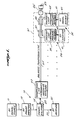
- FIGURE 1 illustrates the presently preferred embodiment of a broadband, inductively coupled, duplex, radio frequency transmission system formed in accordance with the invention. More specifically, FIGURE 1 illustrates a central unit 10 formed by an RF signal source 11 connected through an RF power amplifier 13 to a signal splitter 15. The RF signal source creates RF signals, preferably lying in the 40 MHz to 300 MHz band. Preferably, the cables 17 and 19 connecting the RF signal source to the RF power amplifier and the RF power amplifier 13 to the signal splitter 15, respectively, are coaxial cables.
- the RF power amplifier 13 is a low distortion power amplifier designed to avoid creating harmonics or intermodulation products on its output that might cause interchannel interference between the channels of an entertainment and service system, or cause electromagnetic interference (EMI) with respect to the communications and avionic systems of an aircraft in which the invention is utilized.
- EMI electromagnetic interference
- the central unit 10 also includes an RF receiver 21 connected to the signal splitter 15 via a cable 23, preferably a coaxial cable.
- the signal splitter 15 separates the transmitted and received signals, which are coupled to a balanced transmission line 25 through a transmission line impedance matching network 27, which also forms part of the central unit 10.
- the signal splitter 15 Is connected to the transmission line impedance matching network 27 by a coaxial cable 29.
- the impedance matching network 27 transforms or matches the characteristic impedance of the connecting coaxial cable 29 to that of the balanced transmission line 25 in a conventional manner.
- the transmission line impedance matching network 27 may transform or match the 75 ohm characteristic impedance of one type of standard coaxial cable to the 380 ohm impedance of a suitable balanced transmission line.
- the transmission line impedance matching network converts the unbalanced signal carried by the coaxial cable 29 into a balanced signal suitable for application to the balanced transmission line 25.
- the balanced transmission line 25 conveys radio frequency signals between the central unit 10 and a plurality of remote units 31, only one of which is illustrated in FIGURE 1.
- the remote units 31 are located in the passenger seat groups located within the cabin of the aircraft.
- Each of the remote units 31 includes a receiving section 33 and a transmitting section 35.
- Each of the receiving sections includes a U-shaped coupler 37, a receiver loop impedance matching network 39, and an RF receiver 41.
- Each of the transmitting sections includes a U-shaped coupler 43, a transmit loop impedance matching network 45, and an RF signal source 47.
- the U-shaped couplers 37 and 43 each include a pair of parallel legs joined by cross-members. The cross-members are straight and unitarily join the legs at right angles.
- the legs of the U-shaped coupler 37 of the receiver section 33 are connected to the input of the receiver loop impedance matching network.
- the output of the receiver loop impedance matching network 39 is connected to the RF receiver 31 via a cable 49, preferably a coaxial cable.
- the output of the RF signal source 47 is connected to the input of the transmit loop impedance matching network 45 via a cable 51, preferably a coaxial cable.
- the output of the transmit loop impedance matching network 45 is connected to the legs of the U-shaped coupler of the transmit section 35.
- signals transmitted by the RF signal source 11 of the central unit 10 and applied to the balanced transmission line 25 are detected by the U-shaped coupler 37 of the receiver section 33.
- the signals detected by the U-shaped coupler 37 of the receiver section 33 are applied to the RF receiver 41 of the receiver section via the receiver loop impedance matching network 39.
- the combination of the U-shaped coupler 37 and the receiver loop impedance matching network 39 provide an efficient, low distortion method of coupling signals from the balanced transmission line 25 to an unbalanced cable 49, which forms an unbalanced transmission line, without a physical connection between the two transmission lines.
- Signals produced by the RF signal source 47 of the receive section 35 are coupled to the transmit U-shaped coupler 43 via the transmit loop impedance matching network 45.
- the transmit loop impedance matching network 45 impedance matches the unbalanced cable 51 that connects the RF signal source 47 to the transmit loop impedance matching network 45 to the U-shaped coupler 43.
- the combination of the U-shaped transmit coupler 43 and the transmit loop impedance matching network 45 provides an efficient, low distortion method of coupling signals from the unbalanced cable 51 to the balanced transmission line without the use of physical connectors.
- the balanced transmission line 25 terminates in a characteristic impedance 53, which may be coupled to the end of the balanced transmission line 25 via an impedance matching transformer 55, if desired.
- a characteristic impedance 53 which may be coupled to the end of the balanced transmission line 25 via an impedance matching transformer 55, if desired.
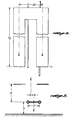
- critical parameters in the design of a broadband, inductively coupled, duplex, RF transmission system formed in accordance with the invention are the physical and electrical relationships between the balanced transmission line, the U-shaped couplers, and the metal structure of the aircraft.
- FIGURES 2 and 3 illustrate how a transmission line and U-shaped couplers formed in accordance with the invention should be mounted in an aircraft. The mounting arrangement is best described using certain mathematical relationships, set forth next.
- the characteristic impedance of a balanced transmission line is defined by the following equation: where, as shown in FIGURE 3:
- the circuit illustrated in FIGURE 4 has an optimally flat frequency response if for a given R p and Z o , and for an L s value determined by Equation (4) the series capacitance, C o , of the impedance matching network can be defined by the following equation:
- the invention provides a broadband, inductively coupled, duplex, RF transmission system suitable for communicating between a central unit and a plurality of remote units.
- the central unit includes an RF signal source and an RF receiver.
- the central unit is connected to one end of a balanced transmission line, preferably via a signal splitter and a transmission line impedance matching network.
- Each remote unit includes a receiving section and a transmitting section separate from one another.
- Each receiving section and each transmitting section includes a U-shaped coupler position so as to overlie the balanced transmission line, in close proximity thereto.
- the U-shaped couplers are oriented such that the cross-members of the U-shaped couplers lie orthogonal to the balanced transmission line and the legs of the U-shaped couplers lie parallel to the balanced transmission line.
- the legs of the U-shaped couplers are connected to electronic transmit and receive sections, via impedance matching networks.
- the U-shaped couplers are formed of flat, rectangular, conductor strips having a U shape, i.e., a pair of parallel legs and a cross-member.
- a transmission system formed in accordance with the invention is highly efficient due to the tight signal coupling between the U-shaped couplers and the balanced transmission line.
- the balanced configuration of the transmission line minimizes the effect of interfering radio frequency signals from other sources and maintains the quality of the transmitted and received signals high.
- High efficiency allows the radio frequency fields radiating from the system to be of relatively low intensity, causing minimal radio interference with other electronic equipment.
Landscapes
- Engineering & Computer Science (AREA)
- Computer Networks & Wireless Communication (AREA)
- Signal Processing (AREA)
- Cable Transmission Systems, Equalization Of Radio And Reduction Of Echo (AREA)
- Near-Field Transmission Systems (AREA)
Applications Claiming Priority (2)
| Application Number | Priority Date | Filing Date | Title |
|---|---|---|---|
| US523226 | 1990-05-14 | ||
| US07/523,226 US5084864A (en) | 1990-05-14 | 1990-05-14 | Broadband, inductively coupled, duplex, rf transmission system |
Publications (2)
| Publication Number | Publication Date |
|---|---|
| EP0457379A2 true EP0457379A2 (de) | 1991-11-21 |
| EP0457379A3 EP0457379A3 (en) | 1992-11-25 |
Family
ID=24084163
Family Applications (1)
| Application Number | Title | Priority Date | Filing Date |
|---|---|---|---|
| EP19910200855 Withdrawn EP0457379A3 (en) | 1990-05-14 | 1991-04-11 | Broadband, inductively coupled, duplex, rf transmission system |
Country Status (3)
| Country | Link |
|---|---|
| US (1) | US5084864A (de) |
| EP (1) | EP0457379A3 (de) |
| JP (1) | JPH04230128A (de) |
Cited By (2)
| Publication number | Priority date | Publication date | Assignee | Title |
|---|---|---|---|---|
| WO2001080447A2 (en) * | 2000-04-13 | 2001-10-25 | The Boeing Company | Wireless interface for electronic devices located in enclosed spaces |
| EP0976204B1 (de) * | 1998-02-17 | 2005-11-30 | Koninklijke Philips Electronics N.V. | Sende/empfangsstation mit impedanzangepassten empfangsmitteln für transponderantwortsignale |
Families Citing this family (13)
| Publication number | Priority date | Publication date | Assignee | Title |
|---|---|---|---|---|
| US5519353A (en) * | 1992-06-09 | 1996-05-21 | At&T Corp. | Balanced driver circuit for eliminating inductive noise |
| US6885845B1 (en) * | 1993-04-05 | 2005-04-26 | Ambit Corp. | Personal communication device connectivity arrangement |
| US5615229A (en) * | 1993-07-02 | 1997-03-25 | Phonic Ear, Incorporated | Short range inductively coupled communication system employing time variant modulation |
| US5539360A (en) * | 1994-03-11 | 1996-07-23 | Motorola, Inc. | Differential transmission line including a conductor having breaks therein |
| US5546050A (en) * | 1995-03-14 | 1996-08-13 | The Boeing Company | Radio frequency bus leveling system |
| US5945634A (en) * | 1995-04-24 | 1999-08-31 | Raychem Corporation | Coaxial cable tap with slitted housing and non-piercing tap insert |
| US5801749A (en) * | 1995-12-13 | 1998-09-01 | Sony Corporation | Universal audio/video signal converter |
| US20050039208A1 (en) * | 2001-10-12 | 2005-02-17 | General Dynamics Ots (Aerospace), Inc. | Wireless data communications system for a transportation vehicle |
| US6996369B2 (en) * | 2002-08-22 | 2006-02-07 | Eagle Broadband, Inc. | Repeater for a satellite phone |
| US20050049209A1 (en) * | 2003-08-06 | 2005-03-03 | Chen Andrew Xian | Pharmaceutical compositions for delivering macrolides |
| NZ529291A (en) * | 2003-10-31 | 2006-05-26 | Auckland Uniservices Ltd | Communication method and apparatus |
| US7652844B2 (en) * | 2003-12-24 | 2010-01-26 | Bruce Edwards | System and method for protecting removeable media playback devices |
| US9520919B2 (en) * | 2014-01-30 | 2016-12-13 | Simmonds Precision Products, Inc. | Magnetic wireless ground data link for aircraft health monitoring |
Citations (3)
| Publication number | Priority date | Publication date | Assignee | Title |
|---|---|---|---|---|
| FR2492196A1 (fr) * | 1980-10-15 | 1982-04-16 | Saulnier Dominique | Boucle statique |
| US4428078A (en) * | 1979-03-26 | 1984-01-24 | The Boeing Company | Wireless audio passenger entertainment system (WAPES) |
| EP0260725A2 (de) * | 1986-09-17 | 1988-03-23 | The Boeing Company | Schleifen mit kerngekoppelten Sendern/Empfängern für steckerlose Unterhaltungssysteme |
Family Cites Families (17)
| Publication number | Priority date | Publication date | Assignee | Title |
|---|---|---|---|---|
| US3310736A (en) * | 1967-03-21 | Method and apparatus pgr transmitting signal information prom an enclosed region to an exterior region without direct electrical connection between the regions | ||
| US1189317A (en) * | 1910-11-04 | 1916-07-04 | Hans Von Kramer | Inductive telephone installation. |
| US2394444A (en) * | 1945-03-24 | 1946-02-05 | Farnsworth Television & Radio | Induction radio system |
| US2515663A (en) * | 1945-09-13 | 1950-07-18 | Gen Railway Signal Co | Negative resistance coupling device |
| US2419833A (en) * | 1945-12-12 | 1947-04-29 | Harlan E Grimes | Antenna arrangement for induction communication systems |
| BE793053A (fr) * | 1971-12-20 | 1973-06-20 | Siemens Ag | Montage pour des lignes d'abonnes comportant deux lignes bifilaires symetriques pour la transmission supplementaire de signaux, en particulierpour des video-telephones |
| US3999015A (en) * | 1975-05-27 | 1976-12-21 | Genie Electronics Co., Inc. | Aircraft multi-communications system |
| US4209663A (en) * | 1978-04-06 | 1980-06-24 | Kiichi Sekiguchi | Drive-in theater audio system |
| JPS5943015B2 (ja) * | 1979-07-20 | 1984-10-19 | 株式会社日立国際電気 | 誘導無線方式 |
| JPS607862B2 (ja) * | 1979-07-20 | 1985-02-27 | 株式会社日立国際電気 | 誘導無線通信装置 |
| JPS5711546A (en) * | 1980-06-26 | 1982-01-21 | Kokusai Electric Co Ltd | Data transmission system by inductive radio |
| US4411004A (en) * | 1980-06-27 | 1983-10-18 | Rolm Corporation | Inductively coupled sensing circuit and priority system |
| JPS58215832A (ja) * | 1982-06-09 | 1983-12-15 | Sharp Corp | デ−タ伝送システム |
| US4584707A (en) * | 1985-01-22 | 1986-04-22 | Dataproducts New England, Inc. | Cordless communications system |
| US4747158A (en) * | 1985-01-22 | 1988-05-24 | Data Products New England, Inc. | Cordless communications system |
| WO1988002944A1 (en) * | 1986-10-16 | 1988-04-21 | Sundstrand Data Control, Inc. | Inductive coupled power system |
| JP2581055B2 (ja) * | 1987-02-23 | 1997-02-12 | ソニー株式会社 | 集中制御装置 |
-
1990
- 1990-05-14 US US07/523,226 patent/US5084864A/en not_active Expired - Lifetime
-
1991
- 1991-04-11 EP EP19910200855 patent/EP0457379A3/en not_active Withdrawn
- 1991-05-13 JP JP3107030A patent/JPH04230128A/ja not_active Withdrawn
Patent Citations (3)
| Publication number | Priority date | Publication date | Assignee | Title |
|---|---|---|---|---|
| US4428078A (en) * | 1979-03-26 | 1984-01-24 | The Boeing Company | Wireless audio passenger entertainment system (WAPES) |
| FR2492196A1 (fr) * | 1980-10-15 | 1982-04-16 | Saulnier Dominique | Boucle statique |
| EP0260725A2 (de) * | 1986-09-17 | 1988-03-23 | The Boeing Company | Schleifen mit kerngekoppelten Sendern/Empfängern für steckerlose Unterhaltungssysteme |
Cited By (4)
| Publication number | Priority date | Publication date | Assignee | Title |
|---|---|---|---|---|
| EP0976204B1 (de) * | 1998-02-17 | 2005-11-30 | Koninklijke Philips Electronics N.V. | Sende/empfangsstation mit impedanzangepassten empfangsmitteln für transponderantwortsignale |
| WO2001080447A2 (en) * | 2000-04-13 | 2001-10-25 | The Boeing Company | Wireless interface for electronic devices located in enclosed spaces |
| WO2001080447A3 (en) * | 2000-04-13 | 2002-06-27 | Boeing Co | Wireless interface for electronic devices located in enclosed spaces |
| US6483865B1 (en) | 2000-04-13 | 2002-11-19 | The Boeing Company | Wireless interface for electronic devices located in enclosed spaces |
Also Published As
| Publication number | Publication date |
|---|---|
| EP0457379A3 (en) | 1992-11-25 |
| JPH04230128A (ja) | 1992-08-19 |
| US5084864A (en) | 1992-01-28 |
Similar Documents
| Publication | Publication Date | Title |
|---|---|---|
| CN100583682C (zh) | 使用单个天线来实现真正的分集接收的方法和设备 | |
| US5084864A (en) | Broadband, inductively coupled, duplex, rf transmission system | |
| US5151838A (en) | Video multiplying system | |
| US6819199B2 (en) | Balun transformer with means for reducing a physical dimension thereof | |
| US4772870A (en) | Power line communication system | |
| US7796890B1 (en) | Hybrid PON/surface wave terrestrial access | |
| EP0799525B1 (de) | Kopplungsvorrichtung zur verbindung einer symmetrischen signalleitung mit einer asymmetrischen signalleitung | |
| US4428078A (en) | Wireless audio passenger entertainment system (WAPES) | |
| CN1744378B (zh) | 用于通信的分布装置和方法 | |
| US20070176840A1 (en) | Multi-receiver communication system with distributed aperture antenna | |
| JP2003531551A (ja) | 電力線通信のための伝送システム及び方法 | |
| US5678210A (en) | Method and apparatus of coupling a transmitter to a waveguide in a remote ground terminal | |
| US8378921B2 (en) | Broadband multi-tap antenna | |
| US20200014087A1 (en) | Plug connector for connecting a waveguide to at least one electric conductor | |
| US9408306B2 (en) | Antenna array feeding structure having circuit boards connected by at least one solderable pin | |
| US10425150B1 (en) | Remotely-managed aircraft RF communication network, device, and method | |
| CN209329171U (zh) | 组合天线 | |
| CN111710948B (zh) | 一种合路器 | |
| US4902989A (en) | Local area network coaxial cable connection device | |
| US20060103238A1 (en) | Feed line structure | |
| US6511234B1 (en) | Signal transmission method and motherboard structure | |
| US20070252661A1 (en) | Manifold combiner for multi-station broadcast sites apparatus and method | |
| EP0935865B1 (de) | Elektrischer datenkoppler mit spannungs- und stromtransformator | |
| US20050077981A1 (en) | Radio frequency connector port with isolation function | |
| KR100591856B1 (ko) | 무선중계장치 |
Legal Events
| Date | Code | Title | Description |
|---|---|---|---|
| PUAI | Public reference made under article 153(3) epc to a published international application that has entered the european phase |
Free format text: ORIGINAL CODE: 0009012 |
|
| AK | Designated contracting states |
Kind code of ref document: A2 Designated state(s): DE FR GB IT NL |
|
| PUAL | Search report despatched |
Free format text: ORIGINAL CODE: 0009013 |
|
| AK | Designated contracting states |
Kind code of ref document: A3 Designated state(s): DE FR GB IT NL |
|
| 17P | Request for examination filed |
Effective date: 19921202 |
|
| STAA | Information on the status of an ep patent application or granted ep patent |
Free format text: STATUS: THE APPLICATION IS DEEMED TO BE WITHDRAWN |
|
| 18D | Application deemed to be withdrawn |
Effective date: 19940103 |