EP0457330A2 - Image forming apparatus - Google Patents
Image forming apparatus Download PDFInfo
- Publication number
- EP0457330A2 EP0457330A2 EP91107970A EP91107970A EP0457330A2 EP 0457330 A2 EP0457330 A2 EP 0457330A2 EP 91107970 A EP91107970 A EP 91107970A EP 91107970 A EP91107970 A EP 91107970A EP 0457330 A2 EP0457330 A2 EP 0457330A2
- Authority
- EP
- European Patent Office
- Prior art keywords
- image
- pixel information
- image forming
- forming apparatus
- image carrier
- Prior art date
- Legal status (The legal status is an assumption and is not a legal conclusion. Google has not performed a legal analysis and makes no representation as to the accuracy of the status listed.)
- Granted
Links
Images


Classifications
-
- G—PHYSICS
- G03—PHOTOGRAPHY; CINEMATOGRAPHY; ANALOGOUS TECHNIQUES USING WAVES OTHER THAN OPTICAL WAVES; ELECTROGRAPHY; HOLOGRAPHY
- G03G—ELECTROGRAPHY; ELECTROPHOTOGRAPHY; MAGNETOGRAPHY
- G03G15/00—Apparatus for electrographic processes using a charge pattern
- G03G15/50—Machine control of apparatus for electrographic processes using a charge pattern, e.g. regulating differents parts of the machine, multimode copiers, microprocessor control
- G03G15/5008—Driving control for rotary photosensitive medium, e.g. speed control, stop position control
-
- B—PERFORMING OPERATIONS; TRANSPORTING
- B41—PRINTING; LINING MACHINES; TYPEWRITERS; STAMPS
- B41J—TYPEWRITERS; SELECTIVE PRINTING MECHANISMS, i.e. MECHANISMS PRINTING OTHERWISE THAN FROM A FORME; CORRECTION OF TYPOGRAPHICAL ERRORS
- B41J2/00—Typewriters or selective printing mechanisms characterised by the printing or marking process for which they are designed
- B41J2/435—Typewriters or selective printing mechanisms characterised by the printing or marking process for which they are designed characterised by selective application of radiation to a printing material or impression-transfer material
- B41J2/47—Typewriters or selective printing mechanisms characterised by the printing or marking process for which they are designed characterised by selective application of radiation to a printing material or impression-transfer material using the combination of scanning and modulation of light
- B41J2/471—Typewriters or selective printing mechanisms characterised by the printing or marking process for which they are designed characterised by selective application of radiation to a printing material or impression-transfer material using the combination of scanning and modulation of light using dot sequential main scanning by means of a light deflector, e.g. a rotating polygonal mirror
-
- G—PHYSICS
- G06—COMPUTING; CALCULATING OR COUNTING
- G06K—GRAPHICAL DATA READING; PRESENTATION OF DATA; RECORD CARRIERS; HANDLING RECORD CARRIERS
- G06K15/00—Arrangements for producing a permanent visual presentation of the output data, e.g. computer output printers
- G06K15/02—Arrangements for producing a permanent visual presentation of the output data, e.g. computer output printers using printers
- G06K15/12—Arrangements for producing a permanent visual presentation of the output data, e.g. computer output printers using printers by photographic printing, e.g. by laser printers
- G06K15/1204—Arrangements for producing a permanent visual presentation of the output data, e.g. computer output printers using printers by photographic printing, e.g. by laser printers involving the fast moving of an optical beam in the main scanning direction
- G06K15/1219—Detection, control or error compensation of scanning velocity or position, e.g. synchronisation
-
- G—PHYSICS
- G06—COMPUTING; CALCULATING OR COUNTING
- G06K—GRAPHICAL DATA READING; PRESENTATION OF DATA; RECORD CARRIERS; HANDLING RECORD CARRIERS
- G06K15/00—Arrangements for producing a permanent visual presentation of the output data, e.g. computer output printers
- G06K15/02—Arrangements for producing a permanent visual presentation of the output data, e.g. computer output printers using printers
- G06K15/16—Means for paper feeding or form feeding
-
- H—ELECTRICITY
- H04—ELECTRIC COMMUNICATION TECHNIQUE
- H04N—PICTORIAL COMMUNICATION, e.g. TELEVISION
- H04N1/00—Scanning, transmission or reproduction of documents or the like, e.g. facsimile transmission; Details thereof
- H04N1/00567—Handling of original or reproduction media, e.g. cutting, separating, stacking
- H04N1/0057—Conveying sheets before or after scanning
- H04N1/00588—Conveying sheets before or after scanning to the scanning position
-
- H—ELECTRICITY
- H04—ELECTRIC COMMUNICATION TECHNIQUE
- H04N—PICTORIAL COMMUNICATION, e.g. TELEVISION
- H04N1/00—Scanning, transmission or reproduction of documents or the like, e.g. facsimile transmission; Details thereof
- H04N1/00567—Handling of original or reproduction media, e.g. cutting, separating, stacking
- H04N1/0057—Conveying sheets before or after scanning
- H04N1/00591—Conveying sheets before or after scanning from the scanning position
-
- H—ELECTRICITY
- H04—ELECTRIC COMMUNICATION TECHNIQUE
- H04N—PICTORIAL COMMUNICATION, e.g. TELEVISION
- H04N1/00—Scanning, transmission or reproduction of documents or the like, e.g. facsimile transmission; Details thereof
- H04N1/00567—Handling of original or reproduction media, e.g. cutting, separating, stacking
- H04N1/0057—Conveying sheets before or after scanning
- H04N1/00599—Using specific components
- H04N1/00602—Feed rollers
-
- H—ELECTRICITY
- H04—ELECTRIC COMMUNICATION TECHNIQUE
- H04N—PICTORIAL COMMUNICATION, e.g. TELEVISION
- H04N1/00—Scanning, transmission or reproduction of documents or the like, e.g. facsimile transmission; Details thereof
- H04N1/04—Scanning arrangements, i.e. arrangements for the displacement of active reading or reproducing elements relative to the original or reproducing medium, or vice versa
- H04N1/113—Scanning arrangements, i.e. arrangements for the displacement of active reading or reproducing elements relative to the original or reproducing medium, or vice versa using oscillating or rotating mirrors
- H04N1/1135—Scanning arrangements, i.e. arrangements for the displacement of active reading or reproducing elements relative to the original or reproducing medium, or vice versa using oscillating or rotating mirrors for the main-scan only
-
- H—ELECTRICITY
- H04—ELECTRIC COMMUNICATION TECHNIQUE
- H04N—PICTORIAL COMMUNICATION, e.g. TELEVISION
- H04N1/00—Scanning, transmission or reproduction of documents or the like, e.g. facsimile transmission; Details thereof
- H04N1/04—Scanning arrangements, i.e. arrangements for the displacement of active reading or reproducing elements relative to the original or reproducing medium, or vice versa
- H04N1/12—Scanning arrangements, i.e. arrangements for the displacement of active reading or reproducing elements relative to the original or reproducing medium, or vice versa using the sheet-feed movement or the medium-advance or the drum-rotation movement as the slow scanning component, e.g. arrangements for the main-scanning
Definitions
- the present invention relates to an image forming apparatus using an electrophotographic process and, more particularly to the image forming apparatus which converts character or pattern information into bit map information (pixel information) and forms an image based thereon.
- an electrophotographic type printer is capable of printing with high resolution and in high quality
- numerous printers such as laser, LED and liquid crystal printers have been developed and widely used in recent years.
- a complicated pattern and image are output by utilizing the feature of high quality.
- a controller (such as a controller having an interpreter for the page descriptive language within) for processing complicated image data over one page of printed surface requires an image memory (hereinafter called "page memory") at least for one page.
- page memory an image memory at least for one page.
- image data which are transmitted from computers and other information processing equipment system to printers, are mostly not first-hand raster image data, but coded or programmed data.
- Fig. 1 shows a sectional view of a laser beam printer representing page printers.
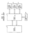
- Fig. 2 is a schematic block diagram of control circuit for a general laser printer.
- numeral 225 shows an information processing equipment (such as a personal computer and work station) outside a laser printer.
- An external interface 227 (such as centronics and RS232C) transmits coded or programmed image information (such as ASCII code and postscript program. These will be hereinafter called "code information") to the laser printer.
- code information is received by an interface circuit 218 within the laser printer.
- a microprocessor 217 receives the code information received by the interface circuit 218, through an internal bus 228.
- This internal bus 228 consists of a data bus, an address bus and a control bus.
- the microprocessor 217 operates in accordance with the control program within the memory 221.
- the memory 221 is a nonvoldatile ROM.
- the microprocessor 217 processes code information obtained from the interface circuit 218 to some degree, and stores in a memory 219.
- the memory 219 is a RAM for storing code information.
- the microprocessor 217 successively stores code information received from outside in a memory 219, and at the same time, converts the coded information into image information of dot image into the RAM 229.
- the RAM 220 is a memory (bit map memory) for storing image data.
- a DMA controller 222 reads out the data stored in the RAM 220, and transmits to a raster conversion circuit 224,
- the DMA controller 222 may have the internal bus 228 to itself independently of the microprocessor 17.
- the microprocessor 217 detects that the image data, which has been stored in the RAM 220, has reached data for one page (that is, when it detects that all code data for one page have been converted into image data)
- the microprocessor 217 activates the DMA controller 222).
- the DMA controller 222 and the microprocessor 217 alternately have the internal bus to each of themselves, successively read out image data from the RAM 220 in accordance with the request of the raster conversion circuit 224, and transmit the image data into the raster conversion circuit 224.
- the raster conversion circuit 224 converts the parallel image data received from the DMA controller 222 into serial image data.
- the serial image data is output into a laser driver (not shown) of a mechanical controller 226 synchronizing with the horizontal synchronizing signal to modulate the laser beam.
- the microprocessor 217 does not only develop code data in image data, but also commands various printing processes to the laser printer mechanical controller 226.
- An I/O driver 223 provides an interface between the microprocessor 217 and the mechanical controller 226.
- numeral 201 shows the main body of the laser printer.
- the microprocessor 217 develops code data for one page, and stores the image data in the memory 220. Then it rotates a carry motor (not shown) through the I/O driver 223. At this time, a photosensitive drum 202, a primary charge roller 205, a development roller 207, a transfer roller 210, a fix roller 215 and a discharge roller 216 start rotating. The rotation of the carry motor is controlled by the mechanical controller 226.
- a laser scanning device 203 has a laser scan mirror, a laser scan motor, a laser light emitting element, and a laser driving circuit within.
- the I/O driver 223 drives the carry motor, and also the laser scan motor within the laser scanning device 203.
- the I/O driver 223 successively applies a high voltage to the primary charge roller 205, the development roller 207, and the transfer roller 210.
- the I/O driver 223 also engages a clutch installed to a paper feed roller 212 to feed transfer material 213 loaded on a paper cassette 214.
- the fed transfer material 213 stops at a resist roller 211 once, and the mechanical controller 226 notifies the I/O driver 223 that the fed transfer material 213 has arrived at the resist roller 211.
- the microprocessor 217 activates the DMA controller 222.
- Serial image data is transmitted from the raster conversion circuit 224.
- the transmitted serial image data is input in the laser scanning device 203, and laser light modulated with the image data is irradiated on the sensitizing drum 202.
- a latent image is formed on its sensitizer surface, and is visualized into a toner image by a development unit 206.
- the code information thus provided by the external information processing equipment is printed on the transfer material 213 as the image information.
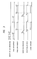
- Fig. 3 To print pages of data, printing is performed with such a timing as shown in Fig. 3.
- the microprocessor 217 starts receiving code information with timing of (a).
- the microprocessor 217 starts developing the image, and stores the image data in the memory 220.
- the microprocessor After completing the reception of the code data on the first page with timing of (b), the microprocessor continuously starts receiving the code information on the second page with timing of (c).
- the microprocessor rotates the carry motor to feed paper with timing of (f).
- the resist roller 211 is driven with timing of (g), and the DMA controller 222 starts reading out the image data with timing of (h).
- a serial image data is formed by the raster conversion circuit 224 with timing of (h) to start laser exposure.
- the laser exposure on the first page is completed with timing of (i). Also, the reception of code information on the second page has been already completed with timing of (e), and the development of image on the second page similarly starts with timing of (i). Thereafter, the printing operation for the second page is performed in the same sequence as on the first page.
- the microprocessor 217 when it has received code information for one page from an external information processing equipment 225 such as the host computer, the microprocessor 217 starts feeding transfer material 213 such as paper, and stops carry of the transfer material 213 in place to allow it to stand by.
- the microprocessor 217 successively transmits this image data of dot image to the mechanical controller 226 as serial image data, and modulates the laser light to expose an electrophotographic sensitising drum 202, and at the same time, to resume the carry from the stand-by state so that the transfer material 213 synchronizes with the exposure image.
- the I/O driver 223 turns off the high voltage to the development roller 207 and the transfer roller 210 to level the surface of the sensitizing drum 202 to an uniform potential only by a primary charge roller 205. Thereafter, the I/O driver stops the drive of the sensitizing drum 202 and the laser scan motor, and stands by until the image development is completed.
- the drum drive and the laser scan motor rotation are started, and then a primary charged high voltage is applied to perform a preparatory operation for printing called a series of "prerotation" such as charging two surfaces of the sensitizing drum to such a state that a latent image can be formed, and adjusting the laser scanning device.
- a primary charged high voltage is applied to perform a preparatory operation for printing called a series of "prerotation" such as charging two surfaces of the sensitizing drum to such a state that a latent image can be formed, and adjusting the laser scanning device.
- a laser scanning device 203 for scanning the laser beam by a polygon mirror, etc., to irradiate the laser light modulated by the image data on the sensitizing drum 202, it is necessary to stably rotate the polygon mirror, etc. and to stably generate a horizontal synchronizing signal to synchronize in the main scan direction.
- the number of revolutions of the polygon mirror is about 6,000 rpm, and it normally takes about 10 seconds for the laser scanning device 203 to irradiate the laser light modulated with the image data.
- FIG. 4 numeral 1 is a sensitizing drum, a static latent image carrier.
- Numeral 2 is light beam emitted from a semiconductor laser.
- a charger 3 uniformly charges the sensitizing drum 1, and a developing device 4 develops a latent image.
- a transfer roller 5 transfers a developed toner image on paper, and a paper feed roller 6 feeds paper 7.
- Numeral 8 is a sensor for detecting paper.
- a resist roller 9 synchronizes the carry of paper with the start of writing an image on the sensitising drum 1.
- a fix roller 10 fixes to paper by melting the toner transferred on paper.
- a paper detection sensor 11 detects the discharge of paper.
- a motor 12 collectively drives each of the above-mentioned roller systems, and driving transmission systems 13 to 20 such as gears transmit the driving of this motor to each roller.
- a switch mechanism 21 cuts off and connects the transmission of a power to drive a paper feed roller 6 by the motor 12, and a switch mechanism 22 cuts off and connects the transmission of a power to drive a resist roller 9 by the motor 12.
- FIG. 5 shows the control unit of a printer having such a configuration.
- a printer control unit 23 collectively controls the printing operation of the printer in accordance with the instruction from a printer controller 24.
- This printer control unit 23 requests each of the following units for driving, and receives input information: an optical system control unit 25 for controlling the drive of an optical system such as scanner control and laser drive, a high voltage control unit 26 for driving high voltage around a sensitising drum such as charge, development, transfer and fix, and a fixer, a carry system control unit 27 for driving a paper carry system, and a sensor input unit 28 for inputting a signal from the sensor.
- an optical system control unit 25 for controlling the drive of an optical system such as scanner control and laser drive
- a high voltage control unit 26 for driving high voltage around a sensitising drum such as charge, development, transfer and fix, and a fixer
- a carry system control unit 27 for driving a paper carry system
- a sensor input unit 28 for inputting a signal from the sensor.
- the printer control unit 23 receives an indication to a printer controller 24, communicates to notify the state of its own, and receives an image signal with a specified timing.
- the resist roller On receipt of a vertical synchronous signal thereafter, 11 the resist roller starts driving to start writing in an image. Thereafter, when the paper discharge sensor has detected the rear end of paper, the high voltage is turned off to stop the scanner motor and motor.
- the sensitizing drum was allowed to be uselessly driven.
- the sensitizing drum had to be quite uselessly rotated until the improper paper feed is judged by the printer control unit to be due to paper clogging, and especially when used in intermittent print, the life of the sensitizing drum was not provided with an optimum control.
- It is an object of the present invention is to solve each of the above-mentioned problems.
- It is another object of the present invention is to provide an image forming apparatus capable of preventing useless deterioration of a sensitizing drum.
- a control of drive/stop of a sensitizing drum is separated from a control of drive/stop of a paper feed roller, and control means, in which the sensitizing drum is driven after a lapse of a specified time from feeding paper, is provided in order to prevent the sensitising drum from being deteriorated due to useless driving.
- the present invention is effective because the sensitizing drum is stopped between pages. Also when paper feed jam occurs, the life can be extended by preventing the drum from deterioration because the sensitizing drum is not driven.
- the present invention it is possible to prevent the lowered image forming speed due to a preparatory period of the image exposure means by putting the image exposure means for forming an image on the sensitizing drum in a preparatory operation condition or in an operating condition before operating the means for driving the image carrier (sensitising drum).
- Fig. 1 is a sectional view of a laser printer according to a prior art.
- Fig. 2 is a schematic block diagram of control circuit of a general laser printer.
- Fig. 3 is a timing chart of assistance in explaining the operation of a laser printer according to the prior art.
- Fig. 4 shows a configuration of another prior art.
- Fig. 5 shows an electric configuration of the prior art.
- Fig. 6 is a timing chart showing the operation of the prior art.
- Fig. 7 is a configuration diagram of the main body of an image forming apparatus (laser printer) 1 of the first embodiment according to the present invention.
- Fig. 8 is a timing chart of assistance in explaining the operation of the first embodiment.
- Fig. 9 is a configuration diagram of the main body of the second embodiment according to the present invention.
- Fig. 10 is a block diagram showing an electric configuration of the second embodiment.
- Fig. 11 is a timing chart of assistance in explaining the operation of the second embodiment.
- Fig. 12 is a timing chart of assistance in explaining the operation of the third embodiment according to the present invention.
- Fig. 13 shows a configuration of the fourth embodiment according to the present invention.
- Fig. 14 is a block diagram showing an electric configuration of the fourth embodiment.
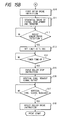
- Fig. 15 is a flow chart of assistance in explaining the operation of the fourth embodiment.
- Fig. 16 is a timing chart showing an example of the operation of the fourth embodiment.
- Fig. 17 shows a configuration of the fifth embodiment according to the present invention.
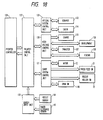
- Fig. 18 is a block diagram showing an electric configuration of the fifth embodiment.
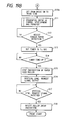
- Fig. 19 is a flow chart of assistance in explaining the operation of the fifth embodiment.
- Fig. 20 is a timing chart showing an example of the operation of the fifth embodiment.
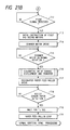
- Fig. 21 is a flow chart of assistance in explaining the operation of the sixth embodiment according to the present invention.
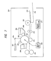
- Fig. 7 is a configuration diagram of the main body showing an image forming apparatus (laser printer) 201 of the first embodiment according to the present invention.
- the configuration of the control unit for generating an image signal and controlling a printer is the same as the configuration in Fig. 2 described in the prior art, and its detailed description is omitted here.
- a feature of the first embodiment of an image forming apparatus is to wait for completion of the image development without stopping the laser scan motor for the laser scanning device 203 though the drum drive is stopped after leveling the surface of the sensitizing drum 202 to an uniform potential only by the primary charge when a time required to convert the coded character or pattern information received from the information processing equipment from the time of starting the paper feed operation into pixel information is longer than a predetermined time Tf in order to prevent the deteriorated sensitizing drum 202 due to charging for a long time, and the surface peeling or surface flaw of the sensitizing drum 202 at a cleaner 209 due to rotation of the sensitizing drum 202 for a long time, the worn cleaner 209, etc. and to prevent the lowered throughput.
- the surface of the electrophotographic sensitizer (sensitizing drum) 202 is uniformly charged by a charge roller 205, and the image is exposed to form the latent image by irradiating laser light from the laser scanning device 203 on the sensitizing drum 202 through a reflective mirror 204. Then a toner 208 within a developing device 206 is developed by a development roller 207.
- transfer material 213 loaded on a paper cassette 214 is fed by a paper feed roller 212, and stands by while its front end is held between resist rollers 211. It is fed to a transfer roller 210 so that it is synchronized with the image written on the sensitizing drum 202, and the image is transferred.
- the image transferred on the transfer material 213 is fixed by the fixer 215, and is discharged outside the machine.
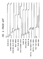
- FIG. 8 An example of timing chart for sequence operation of the embodiment according to the present invention is shown in Fig. 8. In this example, it is assumed that coded information for three pages have been received in periods (a) to (b), (i) to (j) and (p) to (q).
- the control unit including the microprocessor 217 First with reception of the code information, the development of image for code information (code information received for a period (a) to (b)) on the first page is started in the control unit including the microprocessor 217.
- the carry motor is driven with timing of (c) to drive the sensitizing drum 202 (drum drive), and at the same time, the laser scan motor is driven (scanner rotation).
- the primary charge and transfer bias are successively applied to start a preparatory operation for printing called a series of "pre-rotation” such as uniformly charging the surfaces of the sensitizing drum 202 and adjusting the laser beam output.
- a series of "pre-rotation” such as uniformly charging the surfaces of the sensitizing drum 202 and adjusting the laser beam output.
- the image data is not read out, but stands by.
- read-out of the image data starts with timing of (f). Since a time between a time (d) of starting the paper feed pickup operation and a time (e) of completing the image development is less than time Tf for the first page in this case, a signal for stopping the drum is not transmitted.
- the image is written in the sensitizing drum 202 by modulating the laser light from the laser scanning device 203.
- the resist roller 211 is driven so that the transfer material 213, which has reached the resist roller 211, is synchronized with this sensitizing drum 202 (assuming that the sensitizing drum 202 moves over a distance l1 between the laser exposure position and the transfer roller 210 in a time T1 and the transfer material 213 moves over a distance l2( ⁇ l1) between the resist roller 211 and the transfer roller 210 in a time T2, with timing of (g) which is late by the difference between T1 and T2 (T1 - T2)).
- the paper feed pickup operation for the second page is being performed with timing of (k) while the image data on the first page is being read out. Since the image development for the second page is longer than the interpaper processing time, the front end of the transfer material is held between resist rollers 211, and waits for the completion of the image development in a formed loop state.
- Tf has not elapsed from the time (k) of starting the paper feed pickup operation, and therefore, the transfer material 213 is fed with timing of (n) without a drum stop signal transmitted, and the image data is read out with timing of (m).
- a paper feed pickup operation for the third page is performed with timing of (r) while the image data on the second page is being read out in the same manner as on the second page. After the image data on the second page has been read out, image development on the third page is started.
- the microprocessor 217 Since the image development on the third page has not been completed after a lapse of a period Tf from the time (r) of starting the paper feed pickup operation, the microprocessor 217 signals the stop of the drum with timing of (s).
- This signal sets the transfer bias to off, only the primary charge levels the surface of the sensitizing drum 202 to an uniform potential, and a drive unit 230 stops the drum (t). At this time, however, the scanner rotation does not stop unlike when the printer operation stops.
- the drum stop signal stops with timing of (v). This starts driving the drum again with timing of (w), the primary charge is performed, and the resist roller 11 is driven with timing of (y) to feed the transfer material 213. Since the scanner rotation has not stopped, the image data is read out with timing of (x) as soon as the surface of the sensitizing drum 202 is ready for forming a latent image.
- the transfer bias and the primary charge bias are set to off to stop the drum drive. Therefore, it is possible to prevent the deteriorated sensitizing drum 202 due to charging for a long time, and the surface peeling and flaw of the sensitizing drum 202 at a cleaner 209 due to rotation of the sensitizing drum 202 for a long time, and the worn cleaner 209.
- the laser scan motor Since the laser scan motor is rotating even while the sensitizing drum 202 is stopped, the printing speed does not lower due to the preparatory operation for the laser scanning device during restarting after the image development is completed.
- this image forming apparatus (laser printer) has not received the code information on the third page and after, no peper feed operation on the fourth page is performed.
- the transfer bias is set to off, only the primary charge levels the surface of the sensitizing drum 202 to an uniform potential, and the transfer material 213 is discharged outside the machine. Then the drum drive and scanner rotation stop to stop the printer.
- the Tf value differs with various conditions such as the material of the sensitizing drum 202, configuration of the cleaner 209, and process speed.
- a sensitising drum obtained by dispersing phthalocyanine pigment as a charge generating layer to an aluminum cylinder 30 dia. using styrene resin as a binder, or a sensitizing drum obtained by dispersing hydrazone system compound as a charge transporting layer using polycarbonate resin as a binder is used.
- a cleaner obtained by abutting an urethane rubber blade 2 mm thick and with 65 degrees (JIS-A) in hardness at an angle of 22° in the counter direction of the sensitizing drum 202 is used.
- JIS-A degrees in hardness at an angle of 22° in the counter direction of the sensitizing drum 202
- character data in which image development is completed within three seconds, is used for nine prints out of 10 prints, and character and pattern data, in which more than 10 minutes are required to develop an image, are used for one print.
- the Tf value should be within three minutes, and preferably about 1 minute.
- the Tf value should be preferably further shorter.
- the Tf value may be 10 to 30 minutes.
- the Tf value may be automatically or manually changed in accordance with the frequency of printing, in which it takes time to develop an image.
- the Tf value is lower than the above-mentioned values.
- the Tf value may be higher.
- laser lighting to generate a horizontal synchronizing signal is preferably continued in order to eliminate the rise time for the laser scanning device 203.
- the laser lighting may be stopped after a lapse of a specified time to extend the laser life.
- timing was started with the paper feed pickup operation, but timing may be started when starting the image development, or after the paper feed pickup operation has been completed.
- a feature of the embodiment according to the present invention is to wait for completion of the image development without stopping the laser scan motor for the laser scanning device 203 though the drum drive is stopped after leveling the surface of the sensitizing drum 202 to an uniform potential only by the primary charge when a time required to convert the coded character or pattern information received from the information processing equipment from the time of starting the paper feed operation into pixel information is longer than a predetermined time Tf in order to prevent the deteriorated sensitizing drum 202 due to charging for a long time, and the surface peeling or surface flaw of the sensitizing drum 202 at a cleaner 209 due to rotation of the sensitizing drum 202 for a long time, the worn cleaner 209, etc. and to prevent the lowered throughput.
- the feature is further to wait for the completion of the image development by stopping the laser scan motor after a lapse of a specified time Ts after stopping the drive of the sensitising drum.
- the embodiment according to the present invention shows an example in which another independent microcomputer 240 have been allowed to handle the mechanical control of the laser printer because the above-mentioned control becomes a load for the microprocessor 217.
- Fig. 9 is a configuration diagram of the main body of an electrophotographic printer of the embodiment according to the present invention. Also a configuration, in which the control of the embodiment is performed, is shown in Fig. 10.
- the configuration illustrated in Fig. 10 is divided into two: a controller unit 300 for mainly handling image information such as reception of code information for image from the external information processing equipment and image development of code information, and a printer unit 302 for controlling the operation of the printer proper.
- the mechanical control of the laser printer is performed by a single chip microcomputer 240.
- the microcomputer 240 there are a motor driver 241, a laser scan motor driver 243, a paper feed clutch 245, a resist roller clutch 246, a sensor 247, a high voltage output circuit 248, a laser modulator 249, a beam detector 251, etc.
- the microcomputer 240 controls those loads in accordance with a command from an I/O driver 223.
- the READY, PRINT, VSREQ, VSYNC, and PRFD signals are transmitted and received between the microcomputer 240 and the I/O driver 223.
- a serial communication line is also prepared to notify the I/O driver 223 of a state of loading of the printer, and to transmit a special command from the I/O driver 223 to the microcomputer 240.
- An image signal (VIDEO signal) output from a raster conversion circuit 224 is input into a laser modulator 249, and beam output from a semiconductor laser 250 is modulated in accordance with the VIDEO signal.
- the laser beam is scanned by the laser scan mirror, and the scanned laser beam falls upon a photodiode 252 located on a scanning path for the laser beam.
- the laser beam is converted into a pulse signal by a beam detector 251.
- the pulse signal output from the beam detector is input into the raster conversion circuit 224 as a horizontal synchronizing signal (HSYNC signal).
- the ready signal RDY is true.
- the controller unit 300 transmits a print signal PRINT to the printer unit 301 with timing of (c).
- the printer unit 301 starts the drum drive and scanner rotation, and successively performs the primary charge, etc. to prepare receiving an image signal.
- the paper feed pickup is also performed with timing of (d), and the front end of the transfer material 213 reaches the resist rollers 211.
- timing of (e) in which a loop is formed, the VSREQ is made true to notify the controller unit 300 that the printer unit 301 is ready for receiving an image signal.
- the printer unit 301 waits for an image signal to be transmitted in this state.
- the image for the code information is developed in the controller unit 300.
- the controller unit 300 transmits VSYNC notifying of the start of the image data transmission with timing of (f), in which the VSREQ is true.
- the image data is read out, and is transmitted to the printer unit 301 as a video signal (VDO) in a period (g) to (h).
- the transfer material 213, which has stood by is fed to the sensitizing drum 202 by timing to synchronise the front end of the image to that of the transfer material 213 through the drive of the resist rollers 211 with timing of (i), and is transferred by a transfer roller 210.
- the controller unit 300 has received code information on the second page in a period (j) to (k), and transmits a prefeed signal (PRFD) to start the paper feed operation irrespective of the operation of the image development means with timing of (l).
- PRFD prefeed signal
- the paper feed pickup is performed with timing of (m), in which the maximum throughput can be obtained from this laser printer.
- the front end of the transfer material 213 reaches the resist rollers 211, and the VSREQ signal is made true to notify the controller that the printer unit is ready for receiving an image signal with timing of (n) in which a loop is formed.
- the printer unit 301 waits for an image signal to be transmitted in this state.
- the image for the code information is developed in the controller unit 300. Since the image development has not been completed after a lapse of Tf from the paper feed pickup operation (m), a drum stop signal is transmitted with timing of (o).
- the single chip microcomputer 240 turns off the primary charge with timing of (p), and stops the drum drive through the motor driver 241 (q).
- the controller unit 300 Since the image development of the controller unit 300 has not been completed after a lapse of Ts from stopping the drum drive, the controller unit 300 transmits a scanner stop signal with timing of (r).
- the single chip microcomputer 240 stops the scanner rotation through the laser scan motor driver 243 (s).
- the controller unit 300 stops the drum stop and scanner stop signals, and the single chip microcomputer 340 in the printer unit 301 resumes the drum drive by rotating the carry motor through the motor driver 341 with timing of (u), and at the same time, resumes also the scanner rotation through the laser scan motor driver 343.
- the primary charge is resumed with timing of (v), and when the laser scanning device is ready for operation thereafter, a VSREQ signal is transmitted.
- the controller unit 300 transmits a VSYNC signal to the printer unit, and the printer unit 301 drives the resist rollers 211 to transfer, on the transfer material 213, the read-out (VDO) image for the image in the controller unit.
- the printer unit 301 enters the post-rotation, and stops the primary charge, drum drive and scanner rotation to complete the operation.
- the Tf value may be determined like the first embodiment.
- the Ts value is determined in accordance with the life of the laser scan motor, especially the life of the polygon mirror bearing.
- a value of (Tf + Ts) is desirable to be within three minutes at a number of revolutions of 6,000 rpm using ball bearings. If three minutes are exceeded when the frequency of print with long image development time is very high, runout occurs on the polygon mirror surface, and the image is uneven in the subscan direction.
- the value of (Tf + Ts) may be changed in accordance with this frequency. If a polygon mirror bearing with such a long life as a thrust bearing is used, the value of (Tf + Ts) may be extended to about ten times as long as the ball bearing.
- controller unit 300 Since the controller unit 300 is separated from the printer unit 301, the embodiment can be widely applied to hosts having various page descriptive languages. Also since the control unit 300 is capable of operating irrespective of the paper feed timing of the printer unit 301, the control is simple.
- a feature of the embodiment according to the present invention is that the controller signals the start of the paper feed operation before coded character or pattern information is received from the information processing equipment in a stand-by state, in which the print operation is available at any time, and that the printer starts the paper feed operation in compliance with this signal and at the same time, starts the scanner rotation before the sensitizing drum 202 is driven.
- control unit for the image forming apparatus is the same as Fig. 10 of the second embodiment, and its description is omitted.
- the ready signal RDY is true.
- the controller unit 300 transmits a prefeed signal PRFD, a signal for starting the paper feed operation, to the printer unit with timing of (a).
- the printer unit 301 Upon receipt of it, the printer unit 301 starts the scanner rotation and the paper feed pickup with timing of (b), and enters a so-called "stand-by" state.
- the controller unit 300 After it has received code information for one page in a period (c) to (d) hereafter, the controller unit 300 transmits a print signal PRT to the printer unit 301 with timing of (e).
- the printer unit 301 Upon receipt of it, the printer unit 301 performs the drum drive and the primary charge at the same time (f), and makes the VSREQ true to notify the controller unit 300 that the printer unit is ready for receiving an image signal (g).
- the image for the code information is developed in the controller unit 300.
- the controller unit 300 transmits VSYNC notifying of the start of the image data transmission with timing of (h), in which the VSREQ is true.
- the image data is read out, and is transmitted to the printer unit 301 as a video signal (VDO) in a period (i) to (j).
- the transfer material 213, which has stood by is fed to the sensitizing drum 202 by timing to synchronise the front end of the image to that of the transfer material 213 through the drive of the resist rollers 211 with timing of (k), and is transferred by a transfer roller 210.
- the printer unit 301 After the image data has been read out, the printer unit 301 enters the post-rotation, and stops the primary charge, scanner rotation and drum drive to complete the operation because the controller unit 300 has received neither a reserve for the next printing nor code information.
- a time from the reception of code information to completion of printing can be shortened because the scanner rotation is started before driving the drum for printing.
- the scanner rotation may be once stopped when the image development has not been completed even if a specified time passed from the prefeed signal PRFD.
- the controller output the prefeed signal PRFD in accordance with the command from an external equipment in this embodiment
- the prefeed signal may be output in accordance with the received code information for one page, for example, to enter a stand-by state.
- a feature of the embodiment according to the present invention is that the rotary speed R1 of the scanner in a period for waiting for the image development in the first and second embodiments and a period for waiting for a print signal PRT after the prefeed signal PRFD in the third embodiment is reduced less than the rotary speed R2 in a period for reading out the image data.
- the rise time of the scanner rotation greatly depends on a low rotary speed range of the laser scan motor immediately after the start, the rise time of the laser scanning device 203 to the rotary speed R2 can be remarkably shortened by leaving the scanner rotated at the rotary speed R1 in the above-mentioned period.
- This embodiment is effective to prevent noise in addition to extending the life of the laser scanning device 203.
- the above embodiments are a case where the paper feed operation is performed before driving the photosensitive drum.
- Fig. 13 shows a configuration of a printer in the fifth embodiment according to the present invention.
- Numeral 100 is a sensitizing drum
- numeral 101 is a laser beam
- numeral 102 is a semiconductor laser
- numeral 103 is a polygon scanner.
- a charge roller 104 uniformly charges the sensitizing drum 100
- a developing device 105 changes a latent image into a toner image
- a transfer roller 106 transfers a toner image on paper
- a first paper feed roller 107 feeds paper for a first cassette
- a second paper feed roller feeds paper for a second cassette.
- Numeral 109 is a paper cassette.
- a resist sensor 110 detects the presence of paper
- resist rollers 111 synchronizes the carry of paper with writing an image data on the sensitising drum 100
- a fix roller 112 fixes toner transferred on paper by melting
- an exhaust paper sensor 113 checks whether or not the paper has been exhausted
- a first motor 114 drives the first and second paper feed rollers 107 and 108
- resist rollers 111 and a second motor 115 drives the sensitizing drum 100, charge rollers 104, 105 and 106 around the sensitizer drum, and the fix roller 112.
- Driving transmission systems 116, 117 and 118 such as gears transmit the drive of the first motor to the first paper feed roller, the second paper feed roller and the resist roller respectively.
- Driving transmission systems 119 to 123 transmit the drive of the second motor to the sensitizing drum, each charge roller and the fix roller respectively.
- a switch 124 cuts off and transmits the drive of the first motor to the first paper feed roller, a switch 125 cuts off and transmits the drive of the first motor to the second paper feed roller, and a switch 126 cuts off and transmits the drive of the first motor to the resist rollers.
- DC motors or stepping motors, etc. are used for example.
- Fig. 14 shows a block diagram of the control system.
- a printer control unit 127 controls actual printing operation in accordance with a command from a printer controller 128.
- An optical system control unit 129 exercises control of a scanner 133 such as drive/stop of the scanner motor, and control of a laser 134 such as adjustment of light volume of laser beam and ON/OFF due to an image data.
- a high voltage control unit 130 exercises ON-OFF control of high voltage systems 135 to 138 around the sensitising drum, temperature control of the fix roller, etc. in accordance with a command from the printer control unit 127.
- a carry system control unit 131 performs drive/stop of the first and second motors, and drive/stop of the first, second paper feed rollers and the resist rollers in accordance with a command from the printer control unit 127.
- a sensor input unit 132 notifies the printer control unit of the state of a resist sensor 144 and a paper discharge sensor 145.
- a flow chart in Fig. 15 shows what control the printer control unit exercises in such a control system.
- step S1 wait for a print start signal from the printer controller 128, start drive of the scanner motor on receipt of it, and further start drive of the first motor 114 for the paper feed system (step S2).
- step S3 After the scanner reaches a normal rotation (step S3), read whether the first cassette or the second cassette has been designated by the printer controller 128 (step S4), and start drive of the paper feed roller 107, 108 for a cassette in designation respectively (steps S5, S7).
- step S6 set a timer T1 (sec) (step S6) for feed paper from the first cassette or a timer T2 (sec) (step S8) for feed paper from the second cassette beforehand.
- This T1 or T2 is a time required for paper to reach the same point before the resist sensor 110 in Fig. 13 since the paper is fed.
- step S9 command to start the drive of the second motor 115 for the drum system (step S10).
- step S12 judges whether or not paper has reached the resist sensor 110 (step S12).
- step S12 judges whether or not paper has reached the resist sensor 110 (step S12).
- step S13 sets a timer to T3 (sec) in step S13.
- step S14 instruct to stop the paper feed rollers 107 and 108 (step S15), and output a vertical synchronous request signal to the printer controller 128 (step S16).
- step S17 wait for the vertical synchronous signal from the printer controller 128 (step S17), and start writing an image on the sensitising drum on receipt of it (step S18).
- step S18 the same process as the above-mentioned conventional example (Fig. 6) will be performed.
- Fig. 16 shows a timing chart for the above sequence.
- T1 (sec) in Fig. 16 shows the T1 (sec) described in the flow chart in Fig. 15. According to this figure, the driving time for the sensitizing drum 100 is shortened by T o (sec) as compared with the conventional example.
- Figs. 17 and 18 show the second embodiment according to the present invention. This is different from the conventional example in the configuration in that a switch mechanism 146 for cutting off/transmitting a driving transmission system which transmits the drive of a motor 12 to the sensitizing drum and the charge roller system around it, and a control system for the switch mechanism have been provided.
- Fig. 19 shows a flow chart.
- motor drive is started in step S2a, but at this point, the drum system drive swtich 146 is off, that is, the motor drive is not being transmitted.
- the switch 146 is turned on (step S10a) to start driving the drum system.
- Fig. 20 is a timing chart for these processes.
- the drive of the drum system is stopped (point (A) in Fig. 20) after transfer on paper, and the drum system is not driven until paper discharge by the fix roller is completed.
- Fig. 21 shows a sequence when the printer control unit 127 has received, from the printer controller 128, a spare paper feed signal, that is, such a signal that, unlike the print start signal, carries paper to a specified place, allows it to stand by at the position, and thereafter prints through a print start signal.
- a spare paper feed signal that is, such a signal that, unlike the print start signal, carries paper to a specified place, allows it to stand by at the position, and thereafter prints through a print start signal.
- step T1 on receipt of a spare paper feed signal (steps T1, T2) before receiving the print start signal, drive the second motor (step T3) without driving the scanner motor to feed paper (steps T5 to T9) in the same manner as the above-mentioned operation.
- step T10 stop the paper feed and the second motor (steps T10, T11), and wait for a print signal (step T12).
- step T13, T14 On receipt of the print signal, drive the first and second motors and the scanner motor (steps T13, T14), and when the scanner motor reaches a normal number of revolutions (step T15), perform high voltage sequences in order (step T16).
- step T17 drive the paper feed roller again (step T17), and then perform the same operation as in the above-mentioned embodiment (steps T18 to T20).
- the print start signal is output by synchronizing with the completed pixel conversion, and the scanner motor is ensured to be driven when the print start signal is received (when starting to drive the sensitizing drum).
- the scanner motor is driven through the print start signal, and the drive of the sensitizing drum has been started after a lapse of a specified time from the reception of the print start signal.
- both may be optionally combined.
- An image forming apparatus which converts character or pattern information into bit map information (pixel information) and forms an image based thereon.
- the image forming apparatus comprises light-beam generating means for generating modulated light beam, light-beam deflecting means for scanning an image carrier, and driving means for driving the image carrier, and a period has been provided to operate the light-beam deflecting means before starting to drive the image carrier to form an image by the driving means.
Abstract
Description
- The present invention relates to an image forming apparatus using an electrophotographic process and, more particularly to the image forming apparatus which converts character or pattern information into bit map information (pixel information) and forms an image based thereon.
- Since an electrophotographic type printer is capable of printing with high resolution and in high quality, numerous printers such as laser, LED and liquid crystal printers have been developed and widely used in recent years. A complicated pattern and image are output by utilizing the feature of high quality.
- A controller (such as a controller having an interpreter for the page descriptive language within) for processing complicated image data over one page of printed surface requires an image memory (hereinafter called "page memory") at least for one page. To print, for example, on paper A4 in size with a resolution of 300 dpi, a page memory of 1 M byte is required.
- A considerable amount of image information are thus processed by high quality printers. For this reason, image data, which are transmitted from computers and other information processing equipment system to printers, are mostly not first-hand raster image data, but coded or programmed data.
- Accordingly, it represents the performance of a page printer how fast coded image information for one page is converted into raster image information for one page for printing.
- A prior art for form of control of this page printer will be shown below.
- Fig. 1 shows a sectional view of a laser beam printer representing page printers. Fig. 2 is a schematic block diagram of control circuit for a general laser printer.
- In Fig. 2,
numeral 225 shows an information processing equipment (such as a personal computer and work station) outside a laser printer. An external interface 227 (such as centronics and RS232C) transmits coded or programmed image information (such as ASCII code and postscript program. These will be hereinafter called "code information") to the laser printer. The code information is received by aninterface circuit 218 within the laser printer. - A
microprocessor 217 receives the code information received by theinterface circuit 218, through aninternal bus 228. Thisinternal bus 228 consists of a data bus, an address bus and a control bus. Themicroprocessor 217 operates in accordance with the control program within thememory 221. Thememory 221 is a nonvoldatile ROM. - The
microprocessor 217 processes code information obtained from theinterface circuit 218 to some degree, and stores in amemory 219. Thememory 219 is a RAM for storing code information. Themicroprocessor 217 successively stores code information received from outside in amemory 219, and at the same time, converts the coded information into image information of dot image into the RAM 229. The RAM 220 is a memory (bit map memory) for storing image data. - A
DMA controller 222 reads out the data stored in the RAM 220, and transmits to araster conversion circuit 224, TheDMA controller 222 may have theinternal bus 228 to itself independently of themicroprocessor 17. When themicroprocessor 217 detects that the image data, which has been stored in the RAM 220, has reached data for one page (that is, when it detects that all code data for one page have been converted into image data), themicroprocessor 217 activates the DMA controller 222). - The
DMA controller 222 and themicroprocessor 217 alternately have the internal bus to each of themselves, successively read out image data from the RAM 220 in accordance with the request of theraster conversion circuit 224, and transmit the image data into theraster conversion circuit 224. Theraster conversion circuit 224 converts the parallel image data received from theDMA controller 222 into serial image data. The serial image data is output into a laser driver (not shown) of amechanical controller 226 synchronizing with the horizontal synchronizing signal to modulate the laser beam. - The
microprocessor 217 does not only develop code data in image data, but also commands various printing processes to the laser printermechanical controller 226. An I/O driver 223 provides an interface between themicroprocessor 217 and themechanical controller 226. - The mechanical control of a laser printer will be described referring to Fig. 1. In Fig. 1,
numeral 201 shows the main body of the laser printer. Themicroprocessor 217 develops code data for one page, and stores the image data in the memory 220. Then it rotates a carry motor (not shown) through the I/O driver 223. At this time, aphotosensitive drum 202, aprimary charge roller 205, adevelopment roller 207, atransfer roller 210, afix roller 215 and adischarge roller 216 start rotating. The rotation of the carry motor is controlled by themechanical controller 226. - A
laser scanning device 203 has a laser scan mirror, a laser scan motor, a laser light emitting element, and a laser driving circuit within. The I/O driver 223 drives the carry motor, and also the laser scan motor within thelaser scanning device 203. The I/O driver 223 successively applies a high voltage to theprimary charge roller 205, thedevelopment roller 207, and thetransfer roller 210. The I/O driver 223 also engages a clutch installed to apaper feed roller 212 to feedtransfer material 213 loaded on apaper cassette 214. - The fed
transfer material 213 stops at aresist roller 211 once, and themechanical controller 226 notifies the I/O driver 223 that the fedtransfer material 213 has arrived at theresist roller 211. When thetransfer material 213 has stopped at theresist roller 211, themicroprocessor 217 activates theDMA controller 222. - Serial image data is transmitted from the
raster conversion circuit 224. The transmitted serial image data is input in thelaser scanning device 203, and laser light modulated with the image data is irradiated on thesensitizing drum 202. A latent image is formed on its sensitizer surface, and is visualized into a toner image by adevelopment unit 206. - The
transfer material 213, which has stopped at theresist roller 211, is carried by theresist roller 211 again, and the toner image is transferred on thetransfer material 213 by atransfer roller 210. Thetransfer material 213, which has been attached with toner, is heat fixed by afix roller 215, and thereafter is discharged outside the machine by andischarge roller 216. Toner, which has not been transferred on thetransfer material 213 by thetransfer roller 210, is collected in acleaner 209. - The code information thus provided by the external information processing equipment is printed on the
transfer material 213 as the image information. - To print pages of data, printing is performed with such a timing as shown in Fig. 3. In Fig. 3, the
microprocessor 217 starts receiving code information with timing of (a). At the same time, themicroprocessor 217 starts developing the image, and stores the image data in the memory 220. After completing the reception of the code data on the first page with timing of (b), the microprocessor continuously starts receiving the code information on the second page with timing of (c). - After the image on the first page has been developed with timing of (d), the microprocessor rotates the carry motor to feed paper with timing of (f). The
resist roller 211 is driven with timing of (g), and theDMA controller 222 starts reading out the image data with timing of (h). A serial image data is formed by theraster conversion circuit 224 with timing of (h) to start laser exposure. - The laser exposure on the first page is completed with timing of (i). Also, the reception of code information on the second page has been already completed with timing of (e), and the development of image on the second page similarly starts with timing of (i). Thereafter, the printing operation for the second page is performed in the same sequence as on the first page.
- In Fig. 3, periods (a) to (d) and (i) to (j), in which image development is performed, is completely separated from a period (h) to (i) (which is also a laser exposure period) for image data read out, and both have not an overlapped period. This is because the image memory has only one page.
- In such a method, no access to the image memory 220 has been performed in a period of (f) to (h) (or a period of (k) to (m)). Therefore, in LBP with a very long distance between a
paper feed roller 212 and aresist roller 211, the throughput (number of printed sheets per unit time) lowers. If an image memory for two pages is provided, the throughput can be improved by overlapping the image development period with the image data read out period. In this case, however, the memory cost will double. - To solve this defect, the present applicant proposed such a recording apparatus as disclosed in USSN 558,322 filed on July 26, 1990.
- According to this proposal, when it has received code information for one page from an external
information processing equipment 225 such as the host computer, themicroprocessor 217 starts feedingtransfer material 213 such as paper, and stops carry of thetransfer material 213 in place to allow it to stand by. - Thereafter, when it has developed code information in image data of dot image, the
microprocessor 217 successively transmits this image data of dot image to themechanical controller 226 as serial image data, and modulates the laser light to expose an electrophotographic sensitisingdrum 202, and at the same time, to resume the carry from the stand-by state so that thetransfer material 213 synchronizes with the exposure image. - When, however, it takes long to develop the code information in image data of dot image, the deteriorated sensitizing
drum 202 due to charging for a long time, and the surface peeling or surface flaw of the sensitizingdrum 202 at a cleaner 209 due to rotation of the sensitizingdrum 202 for a long time, and worn cleaner 209 occur. - To prevent these troubles, the following method is also considered. That is, after a specified time elapsed in a stand-by state of the transfer material, the I/
O driver 223 turns off the high voltage to thedevelopment roller 207 and thetransfer roller 210 to level the surface of the sensitizingdrum 202 to an uniform potential only by aprimary charge roller 205. Thereafter, the I/O driver stops the drive of the sensitizingdrum 202 and the laser scan motor, and stands by until the image development is completed. - When, however, it takes long to develop the code information in the image data of dot image, this method had the following defects because the laser scan motor is stopped to wait for the completion of the image development.
- After the image development is completed, the drum drive and the laser scan motor rotation are started, and then a primary charged high voltage is applied to perform a preparatory operation for printing called a series of "prerotation" such as charging two surfaces of the sensitizing drum to such a state that a latent image can be formed, and adjusting the laser scanning device.
- To charge the surface of the sensitizing
drum 202 to such a state that a latent image can be formed, allow the surface of the sensitizingdrum 202 to be charged by the primary charge roller twice at most. In an image forming apparatus, for example, with a process speed of 50 mm/sec using a sensitizingdrum 202 with a diameter of 30 mm, it takes about two seconds to charge the surface of the sensitizeddrum 202 to such a state that a latent image can be formed. - In a
laser scanning device 203, on the other hand, for scanning the laser beam by a polygon mirror, etc., to irradiate the laser light modulated by the image data on the sensitizingdrum 202, it is necessary to stably rotate the polygon mirror, etc. and to stably generate a horizontal synchronizing signal to synchronize in the main scan direction. - In an
image forming apparatus 300 dpi, for example, with a process speed of 50 mm/sec using a polygon mirror with six planes, the number of revolutions of the polygon mirror is about 6,000 rpm, and it normally takes about 10 seconds for thelaser scanning device 203 to irradiate the laser light modulated with the image data. - When the laser scan motor is stopped to wait for the completed image development in this way, it takes long especially for the
laser scanning device 203 to rise. Therefore, it took long to print. - Other conventional image forming apparatus had such a configuration as shown in Fig. 4. In Fig. 4,
numeral 1 is a sensitizing drum, a static latent image carrier.Numeral 2 is light beam emitted from a semiconductor laser. Acharger 3 uniformly charges the sensitizingdrum 1, and a developingdevice 4 develops a latent image. Atransfer roller 5 transfers a developed toner image on paper, and apaper feed roller 6 feeds paper 7.Numeral 8 is a sensor for detecting paper. A resistroller 9 synchronizes the carry of paper with the start of writing an image on the sensitisingdrum 1. - A
fix roller 10 fixes to paper by melting the toner transferred on paper. Apaper detection sensor 11 detects the discharge of paper. Amotor 12 collectively drives each of the above-mentioned roller systems, and drivingtransmission systems 13 to 20 such as gears transmit the driving of this motor to each roller. Aswitch mechanism 21 cuts off and connects the transmission of a power to drive apaper feed roller 6 by themotor 12, and aswitch mechanism 22 cuts off and connects the transmission of a power to drive a resistroller 9 by themotor 12. - Fig. 5 shows the control unit of a printer having such a configuration. A
printer control unit 23 collectively controls the printing operation of the printer in accordance with the instruction from aprinter controller 24. Thisprinter control unit 23 requests each of the following units for driving, and receives input information: an opticalsystem control unit 25 for controlling the drive of an optical system such as scanner control and laser drive, a highvoltage control unit 26 for driving high voltage around a sensitising drum such as charge, development, transfer and fix, and a fixer, a carrysystem control unit 27 for driving a paper carry system, and asensor input unit 28 for inputting a signal from the sensor. - In addition, the
printer control unit 23 receives an indication to aprinter controller 24, communicates to notify the state of its own, and receives an image signal with a specified timing. - The actual printer operation is shown in Fig. 6 Timing Chart.
- First, ① on receipt of a print start signal from the printer controller, ② the motor starts driving, and ③ after a lapse of a specified time, the scanner motor starts driving. When the scanner reaches a normal revolution, ④ ⑤ ⑥ each high voltage for charge, development and transfer is successively turned on. After the sensitizing drum has been initialised, ⑦ the paper feed roller is driven. ⑧ In a specified time after the resist sensor has detected the front end of paper, ⑨ the paper feed roller stops and at the same time, a vertical synchronous request signal is output to the controller.

- On receipt of a vertical synchronous signal thereafter, 11 the resist roller starts driving to start writing in an image. Thereafter, when the paper discharge sensor has detected the rear end of paper, the high voltage is turned off to stop the scanner motor and motor.
- In this conventional example, however, only one motor controls the carry system, and the driving transmission system is directly connected to this motor, and therefore, the sensitising drum is always rotating while the motor is being driven.
- For this reason, during a period from the time the paper feed starts after receiving a print start signal from the controller until the paper reaches a specified positions, the sensitizing drum was allowed to be uselessly driven.
- Also when improper paper feed occurs at the paper feed unit, the sensitizing drum had to be quite uselessly rotated until the improper paper feed is judged by the printer control unit to be due to paper clogging, and especially when used in intermittent print, the life of the sensitizing drum was not provided with an optimum control.
- It is an object of the present invention is to solve each of the above-mentioned problems.
- It is another object of the present invention is to provide an image forming apparatus capable of preventing useless deterioration of a sensitizing drum.
- According to an preferred embodiment of the present invention, a control of drive/stop of a sensitizing drum is separated from a control of drive/stop of a paper feed roller, and control means, in which the sensitizing drum is driven after a lapse of a specified time from feeding paper, is provided in order to prevent the sensitising drum from being deteriorated due to useless driving.
- Especially when it takes long to process an image between pages during printing a plurality of pages, the present invention is effective because the sensitizing drum is stopped between pages. Also when paper feed jam occurs, the life can be extended by preventing the drum from deterioration because the sensitizing drum is not driven.
- It is another further object of the present invention to provide an image forming apparatus capable of improving the image forming speed without making the configuration complicated.
- According to the present invention, it is possible to prevent the lowered image forming speed due to a preparatory period of the image exposure means by putting the image exposure means for forming an image on the sensitizing drum in a preparatory operation condition or in an operating condition before operating the means for driving the image carrier (sensitising drum).
- The above-mentioned objects and other objects and merits of the present invention will appear more fully from the attached drawings, the following description and Claims.
- Fig. 1 is a sectional view of a laser printer according to a prior art.
- Fig. 2 is a schematic block diagram of control circuit of a general laser printer.
- Fig. 3 is a timing chart of assistance in explaining the operation of a laser printer according to the prior art.
- Fig. 4 shows a configuration of another prior art.
- Fig. 5 shows an electric configuration of the prior art.
- Fig. 6 is a timing chart showing the operation of the prior art.
- Fig. 7 is a configuration diagram of the main body of an image forming apparatus (laser printer) 1 of the first embodiment according to the present invention.
- Fig. 8 is a timing chart of assistance in explaining the operation of the first embodiment.
- Fig. 9 is a configuration diagram of the main body of the second embodiment according to the present invention.
- Fig. 10 is a block diagram showing an electric configuration of the second embodiment.
- Fig. 11 is a timing chart of assistance in explaining the operation of the second embodiment.
- Fig. 12 is a timing chart of assistance in explaining the operation of the third embodiment according to the present invention.
- Fig. 13 shows a configuration of the fourth embodiment according to the present invention.
- Fig. 14 is a block diagram showing an electric configuration of the fourth embodiment.
- Fig. 15 is a flow chart of assistance in explaining the operation of the fourth embodiment.
- Fig. 16 is a timing chart showing an example of the operation of the fourth embodiment.
- Fig. 17 shows a configuration of the fifth embodiment according to the present invention.
- Fig. 18 is a block diagram showing an electric configuration of the fifth embodiment.
- Fig. 19 is a flow chart of assistance in explaining the operation of the fifth embodiment.
- Fig. 20 is a timing chart showing an example of the operation of the fifth embodiment.
- Fig. 21 is a flow chart of assistance in explaining the operation of the sixth embodiment according to the present invention.
- Fig. 7 is a configuration diagram of the main body showing an image forming apparatus (laser printer) 201 of the first embodiment according to the present invention. The configuration of the control unit for generating an image signal and controlling a printer is the same as the configuration in Fig. 2 described in the prior art, and its detailed description is omitted here.
- A feature of the first embodiment of an image forming apparatus according to the present invention is to wait for completion of the image development without stopping the laser scan motor for the
laser scanning device 203 though the drum drive is stopped after leveling the surface of the sensitizingdrum 202 to an uniform potential only by the primary charge when a time required to convert the coded character or pattern information received from the information processing equipment from the time of starting the paper feed operation into pixel information is longer than a predetermined time Tf in order to prevent the deteriorated sensitizingdrum 202 due to charging for a long time, and the surface peeling or surface flaw of the sensitizingdrum 202 at a cleaner 209 due to rotation of the sensitizingdrum 202 for a long time, theworn cleaner 209, etc. and to prevent the lowered throughput. - In Fig. 7, the surface of the electrophotographic sensitizer (sensitizing drum) 202 is uniformly charged by a
charge roller 205, and the image is exposed to form the latent image by irradiating laser light from thelaser scanning device 203 on the sensitizingdrum 202 through areflective mirror 204. Then atoner 208 within a developingdevice 206 is developed by adevelopment roller 207. - On the other hand,
transfer material 213 loaded on apaper cassette 214 is fed by apaper feed roller 212, and stands by while its front end is held between resistrollers 211. It is fed to atransfer roller 210 so that it is synchronized with the image written on the sensitizingdrum 202, and the image is transferred. The image transferred on thetransfer material 213 is fixed by thefixer 215, and is discharged outside the machine. - Further toner remaining on the sensitizing
drum 202 after the transfer is cleaned by the cleaner 209, and the image forming process after charging is repeated. When a time required to convert the coded character or pattern information received from the information processing equipment from the time of starting the paper feed operation into pixel information exceeds a fixed time Tf, the completion of the image development is waited for without stopping the laser scan motor for thelaser scanning device 203 though the drive of the drum is stopped after leveling the surface of the sensitizingdrum 202 to an uniform potential only by the primary charging. - An example of timing chart for sequence operation of the embodiment according to the present invention is shown in Fig. 8. In this example, it is assumed that coded information for three pages have been received in periods (a) to (b), (i) to (j) and (p) to (q).
- First with reception of the code information, the development of image for code information (code information received for a period (a) to (b)) on the first page is started in the control unit including the
microprocessor 217. When the code information on the first page has been received, the carry motor is driven with timing of (c) to drive the sensitizing drum 202 (drum drive), and at the same time, the laser scan motor is driven (scanner rotation). - Then the primary charge and transfer bias are successively applied to start a preparatory operation for printing called a series of "pre-rotation" such as uniformly charging the surfaces of the sensitizing
drum 202 and adjusting the laser beam output. Hereafter, with timing of (d), in which the image on the sensitisingdrum 202 is synchronized with thetransfer material 213, apaper feed roller 212 is driven to carry thetransfer material 213 to the position of a resist roller 211 (paper feed pickup). - If the pre-rotation has not been completed even if the image development on the first page has been completed with timing of (e), the image data is not read out, but stands by. When the pre-rotation is completed, read-out of the image data starts with timing of (f). Since a time between a time (d) of starting the paper feed pickup operation and a time (e) of completing the image development is less than time Tf for the first page in this case, a signal for stopping the drum is not transmitted.
- With read-out of the image data, the image is written in the sensitizing
drum 202 by modulating the laser light from thelaser scanning device 203. The resistroller 211 is driven so that thetransfer material 213, which has reached the resistroller 211, is synchronized with this sensitizing drum 202 (assuming that the sensitizingdrum 202 moves over a distance ℓ₁ between the laser exposure position and thetransfer roller 210 in a time T₁ and thetransfer material 213 moves over a distance ℓ₂(< ℓ₁) between the resistroller 211 and thetransfer roller 210 in a time T₂, with timing of (g) which is late by the difference between T₁ and T₂ (T₁ - T₂)). - When the static latent image written on the sensitising
drum 202 by the laser exposure comes at the development position, a development bias is applied for development. - When the image data on the first page has been read out with timing of (h), the image development for the code information on the second page which has been received in a period (i) to (j) is started.
- Since the
microprocessor 217 has received the coded information on the second page at this time, the paper feed pickup operation for the second page is being performed with timing of (k) while the image data on the first page is being read out. Since the image development for the second page is longer than the interpaper processing time, the front end of the transfer material is held between resistrollers 211, and waits for the completion of the image development in a formed loop state. - With timing of (1), in which the image development is completed, Tf has not elapsed from the time (k) of starting the paper feed pickup operation, and therefore, the
transfer material 213 is fed with timing of (n) without a drum stop signal transmitted, and the image data is read out with timing of (m). - Since the
microprocessor 217 has received the code information on the third page, a paper feed pickup operation for the third page is performed with timing of (r) while the image data on the second page is being read out in the same manner as on the second page. After the image data on the second page has been read out, image development on the third page is started. - Since the image development on the third page has not been completed after a lapse of a period Tf from the time (r) of starting the paper feed pickup operation, the
microprocessor 217 signals the stop of the drum with timing of (s). - This signal sets the transfer bias to off, only the primary charge levels the surface of the sensitizing
drum 202 to an uniform potential, and adrive unit 230 stops the drum (t). At this time, however, the scanner rotation does not stop unlike when the printer operation stops. - After the image development has been completed with timing of (u), the drum stop signal stops with timing of (v). This starts driving the drum again with timing of (w), the primary charge is performed, and the resist
roller 11 is driven with timing of (y) to feed thetransfer material 213. Since the scanner rotation has not stopped, the image data is read out with timing of (x) as soon as the surface of the sensitizingdrum 202 is ready for forming a latent image. - In an embodiment according to the present invention as mentioned above, when the time for rotation of the sensitizing drum from the paper feed pickup operation exceeds Tf, the transfer bias and the primary charge bias are set to off to stop the drum drive. Therefore, it is possible to prevent the deteriorated sensitizing
drum 202 due to charging for a long time, and the surface peeling and flaw of the sensitizingdrum 202 at a cleaner 209 due to rotation of the sensitizingdrum 202 for a long time, and theworn cleaner 209. - Since the laser scan motor is rotating even while the sensitizing
drum 202 is stopped, the printing speed does not lower due to the preparatory operation for the laser scanning device during restarting after the image development is completed. - Since this image forming apparatus (laser printer) has not received the code information on the third page and after, no peper feed operation on the fourth page is performed. After the image is transferred on the
transfer material 213 on the third page, an operation called "post-rotation" enters, the transfer bias is set to off, only the primary charge levels the surface of the sensitizingdrum 202 to an uniform potential, and thetransfer material 213 is discharged outside the machine. Then the drum drive and scanner rotation stop to stop the printer. - The Tf value differs with various conditions such as the material of the sensitizing
drum 202, configuration of the cleaner 209, and process speed. For example, for the sensitizingdrum 202, a sensitising drum obtained by dispersing phthalocyanine pigment as a charge generating layer to an aluminum cylinder 30 dia. using styrene resin as a binder, or a sensitizing drum obtained by dispersing hydrazone system compound as a charge transporting layer using polycarbonate resin as a binder is used. - For the cleaner 209, a cleaner obtained by abutting an
urethane rubber blade 2 mm thick and with 65 degrees (JIS-A) in hardness at an angle of 22° in the counter direction of the sensitizingdrum 202 is used. In an image forming apparatus with a process speed of 50 mm/sec, character data, in which image development is completed within three seconds, is used for nine prints out of 10 prints, and character and pattern data, in which more than 10 minutes are required to develop an image, are used for one print. - When 7,000 sheets have been printed at such a cycle, in the case of Tf = 5 minutes, the urethane rubber blade in the cleaner 209 has been scratched and improper cleaning occurred. No defective image due to deteriorated sensitizer has occurred.
- In the case of Tf = 3 minutes, no improper cleaning occurs, but the polycarbonate resin in the surface layer of the sensitizing
drum 202 has been peeled, and therefore the electrostatic capacity of the sensitisingdrum 202 has increased. The state of charging due to the primary charging becomes insufficient, causing very slight fog on the image. However, there was no problem, but in the case of Tf = 1 minute, there was no problem at all. - From the foregoing, the Tf value should be within three minutes, and preferably about 1 minute.
- When the frequency of printing, in which it takes time to develop an image, is higher than the above-mentioned condition, the Tf value should be preferably further shorter.
- When the frequency is lower on the contrary, the Tf value may be 10 to 30 minutes.
- Therefore, the Tf value may be automatically or manually changed in accordance with the frequency of printing, in which it takes time to develop an image.
- When such a resin which is easily shaved as acrylic resin is used as the resin for the surface layer of the sensitizing
drum 202, when such a material which is easily scratched as silicone rubber is used as the cleaning blade, or when a fur brush cleaning device or a cleaning device, which abuts on a roller, is used, it is desirable that the Tf value is lower than the above-mentioned values. - When hard material such as amolphous silicon is used for an sensitizer as the sensitizing
drum 202, the Tf value may be higher. - In a state, in which the drum drive is stopped and scanner rotation is continued, laser lighting to generate a horizontal synchronizing signal is preferably continued in order to eliminate the rise time for the
laser scanning device 203. However, the laser lighting may be stopped after a lapse of a specified time to extend the laser life. - Also in the above-mentioned embodiment, timing was started with the paper feed pickup operation, but timing may be started when starting the image development, or after the paper feed pickup operation has been completed.
- A feature of the embodiment according to the present invention is to wait for completion of the image development without stopping the laser scan motor for the
laser scanning device 203 though the drum drive is stopped after leveling the surface of the sensitizingdrum 202 to an uniform potential only by the primary charge when a time required to convert the coded character or pattern information received from the information processing equipment from the time of starting the paper feed operation into pixel information is longer than a predetermined time Tf in order to prevent the deteriorated sensitizingdrum 202 due to charging for a long time, and the surface peeling or surface flaw of the sensitizingdrum 202 at a cleaner 209 due to rotation of the sensitizingdrum 202 for a long time, theworn cleaner 209, etc. and to prevent the lowered throughput. The feature is further to wait for the completion of the image development by stopping the laser scan motor after a lapse of a specified time Ts after stopping the drive of the sensitising drum. - The embodiment according to the present invention shows an example in which another
independent microcomputer 240 have been allowed to handle the mechanical control of the laser printer because the above-mentioned control becomes a load for themicroprocessor 217. - Fig. 9 is a configuration diagram of the main body of an electrophotographic printer of the embodiment according to the present invention. Also a configuration, in which the control of the embodiment is performed, is shown in Fig. 10. The configuration illustrated in Fig. 10 is divided into two: a
controller unit 300 for mainly handling image information such as reception of code information for image from the external information processing equipment and image development of code information, and a printer unit 302 for controlling the operation of the printer proper. - In Fig. 10, the mechanical control of the laser printer is performed by a
single chip microcomputer 240. As loads for themicrocomputer 240, there are amotor driver 241, a laserscan motor driver 243, apaper feed clutch 245, a resistroller clutch 246, asensor 247, a highvoltage output circuit 248, alaser modulator 249, abeam detector 251, etc. - The
microcomputer 240 controls those loads in accordance with a command from an I/O driver 223. The READY, PRINT, VSREQ, VSYNC, and PRFD signals are transmitted and received between themicrocomputer 240 and the I/O driver 223. In addition, a serial communication line is also prepared to notify the I/O driver 223 of a state of loading of the printer, and to transmit a special command from the I/O driver 223 to themicrocomputer 240. - An image signal (VIDEO signal) output from a
raster conversion circuit 224 is input into alaser modulator 249, and beam output from asemiconductor laser 250 is modulated in accordance with the VIDEO signal. The laser beam is scanned by the laser scan mirror, and the scanned laser beam falls upon aphotodiode 252 located on a scanning path for the laser beam. The laser beam is converted into a pulse signal by abeam detector 251. The pulse signal output from the beam detector is input into theraster conversion circuit 224 as a horizontal synchronizing signal (HSYNC signal). - When code information, in which it comparatively does not take time to develop an image on the first page, is received and code information, in which it takes time to develop an image on the second page, is received, the operation will be described referring to Fig. 11 Timing Chart.
- First when the power has been turned on for a
printer unit 301 and the printer unit is ready for receiving a print signal PRINT at any time, the ready signal RDY is true. After it has received code information for one page in a period (a) to (b) in this state, thecontroller unit 300 transmits a print signal PRINT to theprinter unit 301 with timing of (c). Upon receipt of it, theprinter unit 301 starts the drum drive and scanner rotation, and successively performs the primary charge, etc. to prepare receiving an image signal. - The paper feed pickup is also performed with timing of (d), and the front end of the
transfer material 213 reaches the resistrollers 211. With timing of (e), in which a loop is formed, the VSREQ is made true to notify thecontroller unit 300 that theprinter unit 301 is ready for receiving an image signal. Theprinter unit 301 waits for an image signal to be transmitted in this state. - On the other hand, the image for the code information is developed in the
controller unit 300. After the image development, thecontroller unit 300 transmits VSYNC notifying of the start of the image data transmission with timing of (f), in which the VSREQ is true. Then the image data is read out, and is transmitted to theprinter unit 301 as a video signal (VDO) in a period (g) to (h). - On receipt of the VSYNC signal in the
printer unit 301, thetransfer material 213, which has stood by, is fed to the sensitizingdrum 202 by timing to synchronise the front end of the image to that of thetransfer material 213 through the drive of the resistrollers 211 with timing of (i), and is transferred by atransfer roller 210. - The
controller unit 300 has received code information on the second page in a period (j) to (k), and transmits a prefeed signal (PRFD) to start the paper feed operation irrespective of the operation of the image development means with timing of (l). - On the receipt of the prefeed signal PRFD in the
printer unit 301, the paper feed pickup is performed with timing of (m), in which the maximum throughput can be obtained from this laser printer. The front end of thetransfer material 213 reaches the resistrollers 211, and the VSREQ signal is made true to notify the controller that the printer unit is ready for receiving an image signal with timing of (n) in which a loop is formed. Theprinter unit 301 waits for an image signal to be transmitted in this state. - On the other hand, the image for the code information is developed in the
controller unit 300. Since the image development has not been completed after a lapse of Tf from the paper feed pickup operation (m), a drum stop signal is transmitted with timing of (o). - On the receipt of the drum stop signal in the
printer unit 301, thesingle chip microcomputer 240 turns off the primary charge with timing of (p), and stops the drum drive through the motor driver 241 (q). - Since the image development of the
controller unit 300 has not been completed after a lapse of Ts from stopping the drum drive, thecontroller unit 300 transmits a scanner stop signal with timing of (r). - On the receipt of the scanner stop signal in the printer unit, the
single chip microcomputer 240 stops the scanner rotation through the laser scan motor driver 243 (s). - With timing of (t), in which the image development is completed, the
controller unit 300 stops the drum stop and scanner stop signals, and the single chip microcomputer 340 in theprinter unit 301 resumes the drum drive by rotating the carry motor through the motor driver 341 with timing of (u), and at the same time, resumes also the scanner rotation through the laser scan motor driver 343. - The primary charge is resumed with timing of (v), and when the laser scanning device is ready for operation thereafter, a VSREQ signal is transmitted. The
controller unit 300 transmits a VSYNC signal to the printer unit, and theprinter unit 301 drives the resistrollers 211 to transfer, on thetransfer material 213, the read-out (VDO) image for the image in the controller unit. After the read-out of the image data is completed, theprinter unit 301 enters the post-rotation, and stops the primary charge, drum drive and scanner rotation to complete the operation. - The Tf value may be determined like the first embodiment. The Ts value is determined in accordance with the life of the laser scan motor, especially the life of the polygon mirror bearing. A value of (Tf + Ts) is desirable to be within three minutes at a number of revolutions of 6,000 rpm using ball bearings. If three minutes are exceeded when the frequency of print with long image development time is very high, runout occurs on the polygon mirror surface, and the image is uneven in the subscan direction.
- Since the total number of revolutions of the polygon mirror in the embodiment according to the present invention depends upon the frequency of print with long image development time, the value of (Tf + Ts) may be changed in accordance with this frequency. If a polygon mirror bearing with such a long life as a thrust bearing is used, the value of (Tf + Ts) may be extended to about ten times as long as the ball bearing.
- Since the scanner rotation is once stopped for data having an especially long image development time according to the embodiment of the present invention, uneven image caused by the runout of the polygon mirror surface due to worn bearing in the polygon mirror, etc. can be prevented.
- Since the
controller unit 300 is separated from theprinter unit 301, the embodiment can be widely applied to hosts having various page descriptive languages. Also since thecontrol unit 300 is capable of operating irrespective of the paper feed timing of theprinter unit 301, the control is simple. - A feature of the embodiment according to the present invention is that the controller signals the start of the paper feed operation before coded character or pattern information is received from the information processing equipment in a stand-by state, in which the print operation is available at any time, and that the printer starts the paper feed operation in compliance with this signal and at the same time, starts the scanner rotation before the sensitizing
drum 202 is driven. - The configuration of the control unit for the image forming apparatus is the same as Fig. 10 of the second embodiment, and its description is omitted.
- The sequence of the embodiment according to the present invention in Fig. 12 will be described referring to the timing chart.
- First when the power has been turned on for a
printer unit 301 and the printer unit is ready for receiving a print signal PRT at any time, the ready signal RDY is true. After it receives a command to reserve printing from the information processing equipment in this state, thecontroller unit 300 transmits a prefeed signal PRFD, a signal for starting the paper feed operation, to the printer unit with timing of (a). - Upon receipt of it, the
printer unit 301 starts the scanner rotation and the paper feed pickup with timing of (b), and enters a so-called "stand-by" state. - After it has received code information for one page in a period (c) to (d) hereafter, the
controller unit 300 transmits a print signal PRT to theprinter unit 301 with timing of (e). - Upon receipt of it, the
printer unit 301 performs the drum drive and the primary charge at the same time (f), and makes the VSREQ true to notify thecontroller unit 300 that the printer unit is ready for receiving an image signal (g). - On the other hand, the image for the code information is developed in the
controller unit 300. After the image development, thecontroller unit 300 transmits VSYNC notifying of the start of the image data transmission with timing of (h), in which the VSREQ is true. Then the image data is read out, and is transmitted to theprinter unit 301 as a video signal (VDO) in a period (i) to (j). - On receipt of the VSYNC signal in the
printer unit 301, thetransfer material 213, which has stood by, is fed to the sensitizingdrum 202 by timing to synchronise the front end of the image to that of thetransfer material 213 through the drive of the resistrollers 211 with timing of (k), and is transferred by atransfer roller 210. - After the image data has been read out, the
printer unit 301 enters the post-rotation, and stops the primary charge, scanner rotation and drum drive to complete the operation because thecontroller unit 300 has received neither a reserve for the next printing nor code information. - According to this embodiment, a time from the reception of code information to completion of printing can be shortened because the scanner rotation is started before driving the drum for printing.
- In this embodiment, the scanner rotation may be once stopped when the image development has not been completed even if a specified time passed from the prefeed signal PRFD.
- Also although the controller output the prefeed signal PRFD in accordance with the command from an external equipment in this embodiment, the prefeed signal may be output in accordance with the received code information for one page, for example, to enter a stand-by state.
- A feature of the embodiment according to the present invention is that the rotary speed R1 of the scanner in a period for waiting for the image development in the first and second embodiments and a period for waiting for a print signal PRT after the prefeed signal PRFD in the third embodiment is reduced less than the rotary speed R2 in a period for reading out the image data.
- Generally, since the rise time of the scanner rotation greatly depends on a low rotary speed range of the laser scan motor immediately after the start, the rise time of the
laser scanning device 203 to the rotary speed R2 can be remarkably shortened by leaving the scanner rotated at the rotary speed R1 in the above-mentioned period. - This embodiment is effective to prevent noise in addition to extending the life of the
laser scanning device 203. - According to the study by the present inventor et al. concerning noise from the
laser scanning device 203, it has been found that the wind sing on the polygon mirror surface is dominant. The frequency f of the noise is, assuming the number of revolutions of the polygon mirror to be R (rpm), and the number of the planes of the polygon mirror to be n,

- Since the noise rapidly strikes our ears when its frequency exceeds 300 Hz, it is advisable to meet the following equation:

- For example, in the case of a polygon mirror with n = 6 planes, it is effective to reduce to R < 3000 (rpm).
- The above embodiments, are a case where the paper feed operation is performed before driving the photosensitive drum.
- Fig. 13 shows a configuration of a printer in the fifth embodiment according to the present invention.
Numeral 100 is a sensitizing drum, numeral 101 is a laser beam, numeral 102 is a semiconductor laser, and numeral 103 is a polygon scanner. Acharge roller 104 uniformly charges the sensitizingdrum 100, a developingdevice 105 changes a latent image into a toner image, atransfer roller 106 transfers a toner image on paper, a firstpaper feed roller 107 feeds paper for a first cassette, and a second paper feed roller feeds paper for a second cassette. -
Numeral 109 is a paper cassette. A resistsensor 110 detects the presence of paper, resistrollers 111 synchronizes the carry of paper with writing an image data on the sensitisingdrum 100, afix roller 112 fixes toner transferred on paper by melting, anexhaust paper sensor 113 checks whether or not the paper has been exhausted, afirst motor 114 drives the first and secondpaper feed rollers rollers 111, and asecond motor 115 drives the sensitizingdrum 100,charge rollers fix roller 112. - Driving
transmission systems transmission systems 119 to 123 transmit the drive of the second motor to the sensitizing drum, each charge roller and the fix roller respectively. Aswitch 124 cuts off and transmits the drive of the first motor to the first paper feed roller, aswitch 125 cuts off and transmits the drive of the first motor to the second paper feed roller, and aswitch 126 cuts off and transmits the drive of the first motor to the resist rollers. For the first and second motors, DC motors or stepping motors, etc., for example, are used. - Fig. 14 shows a block diagram of the control system.
- A
printer control unit 127 controls actual printing operation in accordance with a command from aprinter controller 128. An opticalsystem control unit 129 exercises control of ascanner 133 such as drive/stop of the scanner motor, and control of alaser 134 such as adjustment of light volume of laser beam and ON/OFF due to an image data. - A high
voltage control unit 130 exercises ON-OFF control ofhigh voltage systems 135 to 138 around the sensitising drum, temperature control of the fix roller, etc. in accordance with a command from theprinter control unit 127. A carrysystem control unit 131 performs drive/stop of the first and second motors, and drive/stop of the first, second paper feed rollers and the resist rollers in accordance with a command from theprinter control unit 127. Asensor input unit 132 notifies the printer control unit of the state of a resistsensor 144 and apaper discharge sensor 145. - A flow chart in Fig. 15 shows what control the printer control unit exercises in such a control system.
- First in step S1, wait for a print start signal from the
printer controller 128, start drive of the scanner motor on receipt of it, and further start drive of thefirst motor 114 for the paper feed system (step S2). After the scanner reaches a normal rotation (step S3), read whether the first cassette or the second cassette has been designated by the printer controller 128 (step S4), and start drive of thepaper feed roller - At this time, set a timer T₁ (sec) (step S6) for feed paper from the first cassette or a timer T₂ (sec) (step S8) for feed paper from the second cassette beforehand. This T₁ or T₂ is a time required for paper to reach the same point before the resist
sensor 110 in Fig. 13 since the paper is fed. When the time for this timer is up (step S9), command to start the drive of thesecond motor 115 for the drum system (step S10). - Further while performing sequential drive of the high voltage systems around the drum in parallel (step S11), judge whether or not paper has reached the resist sensor 110 (step S12). After the resist
sensor 110 has detected paper, set a timer to T₃ (sec) in step S13. After the time for the timer is up (step S14), instruct to stop thepaper feed rollers 107 and 108 (step S15), and output a vertical synchronous request signal to the printer controller 128 (step S16). Wait for the vertical synchronous signal from the printer controller 128 (step S17), and start writing an image on the sensitising drum on receipt of it (step S18). Thereafter, the same process as the above-mentioned conventional example (Fig. 6) will be performed. - Fig. 16 shows a timing chart for the above sequence.
- T₁ (sec) in Fig. 16 shows the T₁ (sec) described in the flow chart in Fig. 15. According to this figure, the driving time for the sensitizing
drum 100 is shortened by To (sec) as compared with the conventional example. - Figs. 17 and 18 show the second embodiment according to the present invention. This is different from the conventional example in the configuration in that a
switch mechanism 146 for cutting off/transmitting a driving transmission system which transmits the drive of amotor 12 to the sensitizing drum and the charge roller system around it, and a control system for the switch mechanism have been provided. - Quite the same operation as the above-mentioned embodiment can be performed by adopting a configuration, in which the drum can be driven and stopped independently of the feed paper system even if only a motor is thus used. In other words, the drive of the first motor in the above-mentioned embodiment may be only replaced with ON of the drum system switch.
- Fig. 19 shows a flow chart. On receipt of a print signal, motor drive is started in step S2a, but at this point, the drum
system drive swtich 146 is off, that is, the motor drive is not being transmitted. After the time of a timer T₁ (sec) is up, theswitch 146 is turned on (step S10a) to start driving the drum system. Fig. 20 is a timing chart for these processes. To further extend the drum life, the drive of the drum system is stopped (point (A) in Fig. 20) after transfer on paper, and the drum system is not driven until paper discharge by the fix roller is completed. - Fig. 21 shows a sequence when the
printer control unit 127 has received, from theprinter controller 128, a spare paper feed signal, that is, such a signal that, unlike the print start signal, carries paper to a specified place, allows it to stand by at the position, and thereafter prints through a print start signal. For the configuration of the printer, any of the configurations shown in the first and second embodiments can be used, and the sequence is shown with the configuration shown in the first embodiment here. - In the embodiment according to the present invention, on receipt of a spare paper feed signal (steps T1, T2) before receiving the print start signal, drive the second motor (step T3) without driving the scanner motor to feed paper (steps T5 to T9) in the same manner as the above-mentioned operation. Hereafter, stop the paper feed and the second motor (steps T10, T11), and wait for a print signal (step T12). On receipt of the print signal, drive the first and second motors and the scanner motor (steps T13, T14), and when the scanner motor reaches a normal number of revolutions (step T15), perform high voltage sequences in order (step T16).
- Hereafter, drive the paper feed roller again (step T17), and then perform the same operation as in the above-mentioned embodiment (steps T18 to T20).
- Since it is not necessary to uselessly drive the sensitizing
drum 100 when thus feeding spare paper, the effect of extending the drum life can be obtained like the above-mentioned embodiment. - In the
above embodiments 1 to 4, the print start signal is output by synchronizing with the completed pixel conversion, and the scanner motor is ensured to be driven when the print start signal is received (when starting to drive the sensitizing drum). In theembodiments - The above embodiments are only examples of applications of the present invention. The present invention can be applied by modifying in various ways within the scope of the Claims, and those are all within the scope of the present invention.
- An image forming apparatus which converts character or pattern information into bit map information (pixel information) and forms an image based thereon.
- The image forming apparatus comprises light-beam generating means for generating modulated light beam, light-beam deflecting means for scanning an image carrier, and driving means for driving the image carrier, and a period has been provided to operate the light-beam deflecting means before starting to drive the image carrier to form an image by the driving means.
Claims (22)
- An image forming apparatus, comprising:
light-beam generating means for generating light beam modulated on the basis of pixel information;
light-beam deflecting means for scanning an image carrier with light beam generated by the light-beam generating means; and
driving means for driving said image carrier, wherein a period has been provided to operate said light-beam deflecting means before starting to drive the image carrier in order to form an image by said driving means. - The image forming apparatus according to Claim 1, further comprising:
pixel information output means for outputting said pixel information on the basis of code information;
transfer means for transferring an image formed on said image carrier; and
feeding means for feeding transfer material to said transfer means, wherein said feeding means starts paper feed operation before said pixel information output means is ready for outputting pixel information. - The image forming apparatus according to Claim 2, wherein said feeding means allows the fed transfer paper to stop in position until said pixel information output means is ready for outputting pixel information.
- The image forming apparatus according to Claim 3, wherein said driving means stops the drive of an image carrier when said transfer material has stopped in position after a lapse of a specified period.
- The image forming apparatus according to Claim 2, wherein said light-beam deflecting means starts the operation by synchronizing with the start of paper feed operation of the feeding means.
- The image forming apparatus according to Claim 4, wherein said light-beam deflecting means stops when said pixel information output means is not ready for outputting pixel information even if a specified period has elapsed after said image carrier stops the drive.
- The image forming apparatus according to Claim 1, wherein said light-beam deflecting means operates at low speed while said image carrier has stopped driving.
- The image forming apparatus according to Claim 2, wherein said pixel information output means is ready for outputting pixel information when pixel information has been generated on the basis of code information for one page.
- The image forming apparatus according to Claim 2, wherein said pixel information output means outputs a print start signal when said pixel information output means is ready for outputting pixel information.
- An image forming apparatus, comprising:
modulating means for modulating light beam on the basis of pixel information;
scanning means for scanning said light beam;
an image carrier which is exposed by said light beam;
driving means for driving said image carrier; and
feeding means for feeding transfer material, on which an image on said image carrier is to be transferred, to a stand-by position, wherein, when said transfer material is in a stand-by state in a stand-by position after a lapse of a predetermined period, a period, in which the drive of the image carrier by said driving means is at least stopped, and said scanning means operates while the image carrier has stopped, has been provided. - The image forming apparatus according to Claim 10, wherein said scanning means is continuously driven while said image carrier has stopped driving.
- The image forming apparatus according to Claim 10, wherein said scanning means is allowed to stop when said transfer material is in a stand-by state in a stand-by position after a lapse of a specified period after the drive of said image carrier is stopped.
- The image forming apparatus according to Claim 11, wherein said scanning means starts the drive by synchronizing with the start of paper feed operation of the feeding means.
- The image forming apparatus according to Claim 10, wherein said scanning means is driven at low speed while said image carrier has stopped the drive.
- An image forming apparatus comprising:
image forming means for forming an image on an image carrier which is driven for rotation;
transfer means for transferring an image formed on the image carrier on transfer material; and
feeding means for feeding transfer material to said transfer means, wherein said feeding means starts paper feed operation before said image carrier starts the rotation. - The image forming apparatus according to Claim 15, wherein said image forming means comprises light-beam generating means for generating light beam modulated on the basis of pixel information, and light-beam deflecting means for scanning said image carrier with light beam generated by the light-beam generating means, and wherein said light-beam deflecting means starts operation before said image carrier is driven for rotation.
- The image forming apparatus according to Claim 15, further comprising pixel information output means which generates pixel information on the basis of code information, and outputs into said image forming means, wherein said feeding means starts paper feed operation when the pixel information output means is ready for outputting pixel information.
- The image forming apparatus according to Claim 15, further comprising pixel information output means which generates pixel information on the basis of code information, and outputs into said image forming means, wherein said feeding means can start the operation before the pixel information output means is ready for outputting pixel information.
- The image forming apparatus according to Claim 15, wherein said feeding means and said image carrier are driven by a common driving source.
- The image forming apparatus according to Claim 15, wherein said feeding means and said image carrier are individually driven by the respective driving sources.
- An image forming apparatus capable of receiving code information for a plurality of pages and continuously forming images on the basis of code information for each page, comprising:
pixel information output means for outputting pixel information on the basis of code information for each page;
image forming means for forming an image on image carrier, which is driven for rotation, on the basis of pixel information from said pixel information output means;
transfer means for transferring an image formed on said image carrier on transfer material; and
feeding means for feeding transfer material into said transfer means, wherein said apparatus is temporarily capable of stopping the rotation and drive of the image carrier while forming non-image between pages. - The image forming apparatus according to Claim 21, wherein said apparatus temporarily stops the rotation and drive of said image carrier when it takes long to generate pixel information on the basis of code information on the next page by the pixel information output means.
Applications Claiming Priority (6)
| Application Number | Priority Date | Filing Date | Title |
|---|---|---|---|
| JP2128191A JP2840380B2 (en) | 1990-05-17 | 1990-05-17 | Image forming device |
| JP12819190 | 1990-05-17 | ||
| JP128191/90 | 1990-05-17 | ||
| JP2192270A JPH0477756A (en) | 1990-07-19 | 1990-07-19 | Image forming device |
| JP192270/90 | 1990-07-19 | ||
| JP19227090 | 1990-07-19 |
Publications (3)
| Publication Number | Publication Date |
|---|---|
| EP0457330A2 true EP0457330A2 (en) | 1991-11-21 |
| EP0457330A3 EP0457330A3 (en) | 1994-01-12 |
| EP0457330B1 EP0457330B1 (en) | 2000-02-09 |
Family
ID=26463927
Family Applications (1)
| Application Number | Title | Priority Date | Filing Date |
|---|---|---|---|
| EP91107970A Expired - Lifetime EP0457330B1 (en) | 1990-05-17 | 1991-05-16 | Image forming apparatus |
Country Status (4)
| Country | Link |
|---|---|
| US (1) | US5694158A (en) |
| EP (1) | EP0457330B1 (en) |
| DE (1) | DE69131970T2 (en) |
| HK (1) | HK1011746A1 (en) |
Cited By (2)
| Publication number | Priority date | Publication date | Assignee | Title |
|---|---|---|---|---|
| FR2740568A1 (en) * | 1995-11-01 | 1997-04-30 | Canon Kk | IMAGE FORMING APPARATUS |
| EP0785483A3 (en) * | 1996-01-22 | 1998-09-30 | Lexmark International, Inc. | Image forming apparatus with modular staging assembly |
Families Citing this family (9)
| Publication number | Priority date | Publication date | Assignee | Title |
|---|---|---|---|---|
| KR0146533B1 (en) * | 1995-08-14 | 1998-08-17 | 김광호 | Print control method |
| US5978643A (en) * | 1996-03-21 | 1999-11-02 | Ricoh Company, Ltd. | Electrophotographic apparatus which reduces running cost by starting image forming processes in response to sheet detectors |
| JP3767026B2 (en) * | 1996-08-26 | 2006-04-19 | ブラザー工業株式会社 | Multifunctional peripheral device and storage medium |
| AU2001231078A1 (en) * | 2000-01-25 | 2001-08-07 | Vistaprint Usa, Inc. | Managing print jobs |
| US6694110B2 (en) * | 2001-02-19 | 2004-02-17 | Canon Kabushiki Kaisha | Image forming apparatus with variable waiting time conveyance feature |
| JP3728216B2 (en) * | 2001-04-12 | 2005-12-21 | キヤノン株式会社 | Image forming apparatus |
| US6706118B2 (en) * | 2002-02-26 | 2004-03-16 | Lexmark International, Inc. | Apparatus and method of using motion control to improve coatweight uniformity in intermittent coaters in an inkjet printer |
| US7111916B2 (en) * | 2002-02-27 | 2006-09-26 | Lexmark International, Inc. | System and method of fluid level regulating for a media coating system |
| US6955721B2 (en) * | 2002-02-28 | 2005-10-18 | Lexmark International, Inc. | System and method of coating print media in an inkjet printer |
Citations (6)
| Publication number | Priority date | Publication date | Assignee | Title |
|---|---|---|---|---|
| EP0183166A2 (en) * | 1984-11-26 | 1986-06-04 | Ecrm Trust | Dual mode laser printer |
| US4647946A (en) * | 1984-02-15 | 1987-03-03 | Canon Kabushiki Kaisha | Laser beam recorder having synchronized scanner and drum operations |
| US4894669A (en) * | 1988-04-20 | 1990-01-16 | Canon Kabushiki Kaisha | Laser beam printer |
| EP0361857A2 (en) * | 1988-09-27 | 1990-04-04 | Canon Kabushiki Kaisha | Recording apparatus |
| US4933772A (en) * | 1985-10-07 | 1990-06-12 | Minolta Camera Kabushiki Kaisha | Electrophotographic printer with improved timing arrangements |
| EP0410817A2 (en) * | 1989-07-28 | 1991-01-30 | Canon Kabushiki Kaisha | Image forming apparatus |
Family Cites Families (12)
| Publication number | Priority date | Publication date | Assignee | Title |
|---|---|---|---|---|
| US4786923A (en) * | 1982-09-07 | 1988-11-22 | Canon Kabushiki Kaisha | Image recording system for image recording in response to signals entered from a recording information generating unit |
| JPS60113253A (en) * | 1983-11-24 | 1985-06-19 | Canon Inc | Recording device |
| JPH0736600B2 (en) * | 1985-10-11 | 1995-04-19 | 株式会社リコー | Exposure device for laser recording device |
| JPS62187361A (en) * | 1986-02-14 | 1987-08-15 | Canon Inc | Image forming device |
| JPS63124786A (en) * | 1986-11-14 | 1988-05-28 | Canon Inc | Controller for motor |
| JPS6438345A (en) * | 1987-07-31 | 1989-02-08 | Toshiba Corp | Picture forming device |
| JPH0764091B2 (en) * | 1987-10-05 | 1995-07-12 | 沖電気工業株式会社 | Electrophotographic printer |
| US4914456A (en) * | 1987-10-23 | 1990-04-03 | Matsushita Electric Industrial Co., Ltd. | Electrostatographic apparatus |
| JPH01284876A (en) * | 1988-05-12 | 1989-11-16 | Ricoh Co Ltd | Recording device |
| JP2685522B2 (en) * | 1988-08-05 | 1997-12-03 | 株式会社日立製作所 | High precision image recorder |
| JP2755625B2 (en) * | 1988-10-31 | 1998-05-20 | 株式会社東芝 | Image forming device |
| JPH02141770A (en) * | 1988-11-22 | 1990-05-31 | Mita Ind Co Ltd | Digital image forming device |
-
1991
- 1991-05-16 DE DE69131970T patent/DE69131970T2/en not_active Expired - Fee Related
- 1991-05-16 EP EP91107970A patent/EP0457330B1/en not_active Expired - Lifetime
-
1995
- 1995-03-23 US US08/409,937 patent/US5694158A/en not_active Expired - Lifetime
-
1998
- 1998-12-03 HK HK98112757A patent/HK1011746A1/en not_active IP Right Cessation
Patent Citations (6)
| Publication number | Priority date | Publication date | Assignee | Title |
|---|---|---|---|---|
| US4647946A (en) * | 1984-02-15 | 1987-03-03 | Canon Kabushiki Kaisha | Laser beam recorder having synchronized scanner and drum operations |
| EP0183166A2 (en) * | 1984-11-26 | 1986-06-04 | Ecrm Trust | Dual mode laser printer |
| US4933772A (en) * | 1985-10-07 | 1990-06-12 | Minolta Camera Kabushiki Kaisha | Electrophotographic printer with improved timing arrangements |
| US4894669A (en) * | 1988-04-20 | 1990-01-16 | Canon Kabushiki Kaisha | Laser beam printer |
| EP0361857A2 (en) * | 1988-09-27 | 1990-04-04 | Canon Kabushiki Kaisha | Recording apparatus |
| EP0410817A2 (en) * | 1989-07-28 | 1991-01-30 | Canon Kabushiki Kaisha | Image forming apparatus |
Cited By (5)
| Publication number | Priority date | Publication date | Assignee | Title |
|---|---|---|---|---|
| FR2740568A1 (en) * | 1995-11-01 | 1997-04-30 | Canon Kk | IMAGE FORMING APPARATUS |
| EP0772095A1 (en) * | 1995-11-01 | 1997-05-07 | Canon Kabushiki Kaisha | Image forming apparatus |
| US5819149A (en) * | 1995-11-01 | 1998-10-06 | Canon Kabushiki Kaisha | Image forming apparatus preventing change of size of image |
| EP0785483A3 (en) * | 1996-01-22 | 1998-09-30 | Lexmark International, Inc. | Image forming apparatus with modular staging assembly |
| AU703496B2 (en) * | 1996-01-22 | 1999-03-25 | Lexmark International Inc. | Image forming apparatus with modular staging assembly |
Also Published As
| Publication number | Publication date |
|---|---|
| EP0457330A3 (en) | 1994-01-12 |
| DE69131970D1 (en) | 2000-03-16 |
| DE69131970T2 (en) | 2000-07-20 |
| EP0457330B1 (en) | 2000-02-09 |
| US5694158A (en) | 1997-12-02 |
| HK1011746A1 (en) | 1999-07-16 |
Similar Documents
| Publication | Publication Date | Title |
|---|---|---|
| EP0681265B1 (en) | Image forming apparatus | |
| EP0457330B1 (en) | Image forming apparatus | |
| US5184178A (en) | Image recording apparatus having an interchangeable cartridge | |
| US5512927A (en) | Image forming apparatus having a photosensitive drum rotatable at different speeds | |
| JPH1115216A (en) | Image processor, control method therefor and record medium | |
| JP3015076B2 (en) | Image forming device | |
| EP0466172B1 (en) | Sheet feed for an image forming apparatus | |
| JPH0411392B2 (en) | ||
| JP3303382B2 (en) | Image forming device | |
| JP2710365B2 (en) | Image recording device | |
| JPH0216519B2 (en) | ||
| JP2840380B2 (en) | Image forming device | |
| JP2750977B2 (en) | Printing equipment | |
| KR100242121B1 (en) | Method for controlling transcribing voltage | |
| JP3171194B2 (en) | Image recording device | |
| JP2874766B2 (en) | System unit control device | |
| JPH04354465A (en) | Picture forming device | |
| KR100288697B1 (en) | Printing device that supports reduced printing using laser scanning units | |
| JPH07228018A (en) | Printer | |
| US20020081129A1 (en) | Electrophotographic device | |
| JPH0394562A (en) | Digital copying machine | |
| JPH07199774A (en) | Image forming device | |
| JPH04354468A (en) | Picture forming device | |
| JPH04354466A (en) | Picture forming device | |
| JPH04296779A (en) | Recorder |
Legal Events
| Date | Code | Title | Description |
|---|---|---|---|
| PUAI | Public reference made under article 153(3) epc to a published international application that has entered the european phase |
Free format text: ORIGINAL CODE: 0009012 |
|
| AK | Designated contracting states |
Kind code of ref document: A2 Designated state(s): DE FR GB IT |
|
| PUAL | Search report despatched |
Free format text: ORIGINAL CODE: 0009013 |
|
| AK | Designated contracting states |
Kind code of ref document: A3 Designated state(s): DE FR GB IT |
|
| 17P | Request for examination filed |
Effective date: 19940530 |
|
| 17Q | First examination report despatched |
Effective date: 19941004 |
|
| GRAG | Despatch of communication of intention to grant |
Free format text: ORIGINAL CODE: EPIDOS AGRA |
|
| GRAG | Despatch of communication of intention to grant |
Free format text: ORIGINAL CODE: EPIDOS AGRA |
|
| GRAH | Despatch of communication of intention to grant a patent |
Free format text: ORIGINAL CODE: EPIDOS IGRA |
|
| GRAH | Despatch of communication of intention to grant a patent |
Free format text: ORIGINAL CODE: EPIDOS IGRA |
|
| GRAA | (expected) grant |
Free format text: ORIGINAL CODE: 0009210 |
|
| AK | Designated contracting states |
Kind code of ref document: B1 Designated state(s): DE FR GB IT |
|
| REF | Corresponds to: |
Ref document number: 69131970 Country of ref document: DE Date of ref document: 20000316 |
|
| ET | Fr: translation filed | ||
| ITF | It: translation for a ep patent filed |
Owner name: SOCIETA' ITALIANA BREVETTI S.P.A. |
|
| PLBE | No opposition filed within time limit |
Free format text: ORIGINAL CODE: 0009261 |
|
| STAA | Information on the status of an ep patent application or granted ep patent |
Free format text: STATUS: NO OPPOSITION FILED WITHIN TIME LIMIT |
|
| 26N | No opposition filed | ||
| REG | Reference to a national code |
Ref country code: GB Ref legal event code: IF02 |
|
| PGFP | Annual fee paid to national office [announced via postgrant information from national office to epo] |
Ref country code: FR Payment date: 20090520 Year of fee payment: 19 Ref country code: DE Payment date: 20090531 Year of fee payment: 19 Ref country code: IT Payment date: 20090515 Year of fee payment: 19 |
|
| PGFP | Annual fee paid to national office [announced via postgrant information from national office to epo] |
Ref country code: GB Payment date: 20090527 Year of fee payment: 19 |
|
| GBPC | Gb: european patent ceased through non-payment of renewal fee |
Effective date: 20100516 |
|
| REG | Reference to a national code |
Ref country code: FR Ref legal event code: ST Effective date: 20110131 |
|
| PG25 | Lapsed in a contracting state [announced via postgrant information from national office to epo] |
Ref country code: IT Free format text: LAPSE BECAUSE OF NON-PAYMENT OF DUE FEES Effective date: 20100516 |
|
| PG25 | Lapsed in a contracting state [announced via postgrant information from national office to epo] |
Ref country code: DE Free format text: LAPSE BECAUSE OF NON-PAYMENT OF DUE FEES Effective date: 20101201 |
|
| PG25 | Lapsed in a contracting state [announced via postgrant information from national office to epo] |
Ref country code: FR Free format text: LAPSE BECAUSE OF NON-PAYMENT OF DUE FEES Effective date: 20100531 |
|
| PG25 | Lapsed in a contracting state [announced via postgrant information from national office to epo] |
Ref country code: GB Free format text: LAPSE BECAUSE OF NON-PAYMENT OF DUE FEES Effective date: 20100516 |