EP0457166A2 - Gegossener Spritzgiessverteiler - Google Patents
Gegossener Spritzgiessverteiler Download PDFInfo
- Publication number
- EP0457166A2 EP0457166A2 EP91107436A EP91107436A EP0457166A2 EP 0457166 A2 EP0457166 A2 EP 0457166A2 EP 91107436 A EP91107436 A EP 91107436A EP 91107436 A EP91107436 A EP 91107436A EP 0457166 A2 EP0457166 A2 EP 0457166A2
- Authority
- EP
- European Patent Office
- Prior art keywords
- manifold
- extends
- injection molding
- outlet
- melt
- Prior art date
- Legal status (The legal status is an assumption and is not a legal conclusion. Google has not performed a legal analysis and makes no representation as to the accuracy of the status listed.)
- Withdrawn
Links
- 238000001746 injection moulding Methods 0.000 title claims abstract description 13
- 239000000155 melt Substances 0.000 claims abstract description 26
- 238000010438 heat treatment Methods 0.000 claims description 9
- 229910001208 Crucible steel Inorganic materials 0.000 claims description 2
- 238000009434 installation Methods 0.000 claims 1
- 239000000919 ceramic Substances 0.000 abstract description 2
- 238000005266 casting Methods 0.000 abstract 1
- 229910000990 Ni alloy Inorganic materials 0.000 description 5
- 229910000831 Steel Inorganic materials 0.000 description 5
- 239000010959 steel Substances 0.000 description 5
- 238000004519 manufacturing process Methods 0.000 description 4
- 238000000034 method Methods 0.000 description 4
- 238000000465 moulding Methods 0.000 description 4
- 239000000463 material Substances 0.000 description 3
- XKRFYHLGVUSROY-UHFFFAOYSA-N Argon Chemical compound [Ar] XKRFYHLGVUSROY-UHFFFAOYSA-N 0.000 description 2
- IJGRMHOSHXDMSA-UHFFFAOYSA-N Atomic nitrogen Chemical compound N#N IJGRMHOSHXDMSA-UHFFFAOYSA-N 0.000 description 2
- 238000005219 brazing Methods 0.000 description 2
- 238000001816 cooling Methods 0.000 description 2
- 238000002347 injection Methods 0.000 description 2
- 239000007924 injection Substances 0.000 description 2
- 238000002844 melting Methods 0.000 description 2
- 230000008018 melting Effects 0.000 description 2
- 238000005192 partition Methods 0.000 description 2
- 239000000843 powder Substances 0.000 description 2
- 238000007789 sealing Methods 0.000 description 2
- 229910018487 Ni—Cr Inorganic materials 0.000 description 1
- RTAQQCXQSZGOHL-UHFFFAOYSA-N Titanium Chemical compound [Ti] RTAQQCXQSZGOHL-UHFFFAOYSA-N 0.000 description 1
- 229910052786 argon Inorganic materials 0.000 description 1
- QVGXLLKOCUKJST-UHFFFAOYSA-N atomic oxygen Chemical compound [O] QVGXLLKOCUKJST-UHFFFAOYSA-N 0.000 description 1
- VNNRSPGTAMTISX-UHFFFAOYSA-N chromium nickel Chemical compound [Cr].[Ni] VNNRSPGTAMTISX-UHFFFAOYSA-N 0.000 description 1
- 239000002131 composite material Substances 0.000 description 1
- 239000000498 cooling water Substances 0.000 description 1
- 238000000354 decomposition reaction Methods 0.000 description 1
- 230000001419 dependent effect Effects 0.000 description 1
- 239000011261 inert gas Substances 0.000 description 1
- 239000011810 insulating material Substances 0.000 description 1
- 238000009413 insulation Methods 0.000 description 1
- 238000005495 investment casting Methods 0.000 description 1
- CPLXHLVBOLITMK-UHFFFAOYSA-N magnesium oxide Inorganic materials [Mg]=O CPLXHLVBOLITMK-UHFFFAOYSA-N 0.000 description 1
- 239000000395 magnesium oxide Substances 0.000 description 1
- AXZKOIWUVFPNLO-UHFFFAOYSA-N magnesium;oxygen(2-) Chemical compound [O-2].[Mg+2] AXZKOIWUVFPNLO-UHFFFAOYSA-N 0.000 description 1
- 238000012986 modification Methods 0.000 description 1
- 230000004048 modification Effects 0.000 description 1
- 229910052757 nitrogen Inorganic materials 0.000 description 1
- 239000001301 oxygen Substances 0.000 description 1
- 229910052760 oxygen Inorganic materials 0.000 description 1
- 238000005086 pumping Methods 0.000 description 1
- 239000010936 titanium Substances 0.000 description 1
- 229910052719 titanium Inorganic materials 0.000 description 1
Images
Classifications
-
- B—PERFORMING OPERATIONS; TRANSPORTING
- B29—WORKING OF PLASTICS; WORKING OF SUBSTANCES IN A PLASTIC STATE IN GENERAL
- B29C—SHAPING OR JOINING OF PLASTICS; SHAPING OF MATERIAL IN A PLASTIC STATE, NOT OTHERWISE PROVIDED FOR; AFTER-TREATMENT OF THE SHAPED PRODUCTS, e.g. REPAIRING
- B29C45/00—Injection moulding, i.e. forcing the required volume of moulding material through a nozzle into a closed mould; Apparatus therefor
- B29C45/17—Component parts, details or accessories; Auxiliary operations
- B29C45/26—Moulds
- B29C45/27—Sprue channels ; Runner channels or runner nozzles
- B29C45/2725—Manifolds
- B29C2045/273—Manifolds stacked manifolds
Definitions
- This invention relates to injection molding and more particularly to a heated melt conveying manifold for a multi-cavity injection molding system.
- Heated manifolds for distributing melt from a common inlet to a number of spaced outlets are well known in the art. It is also well known that the length and size of the melt passage through the manifold must be equal or balanced and that sharp bends or corners are not acceptable as they can result in decomposition of the melt due to undue stress.
- An example of a bridging manifold system is shown in the applicant's U.S. patent number 4,761,342 which issued August 2, 1988.
- the various elongated manifolds were made by the composite plate method described in the applicant's U.S. patent number 4,648,546 which issued March 10, 1987. As can be seen, while they are suitable for many applications, these manifolds have the disadvantage that the portions of the melt passage having the smoothly curved bends necessarily extend in a single plane.
- the invention provides an injection molding cast steel manifold comprising a rear surface, a forward surface which extends parallel to the rear surface, and a melt passage which extends therethrough from the rear surface to the forward surface, the melt passage having a common inlet portion which extends forwardly from a central inlet on the rear surface, the melt passage having more than two identical equally radially spaced outlet portions which branch outwardly from the common inlet portion, each outlet portion extending around a first smoothly curved bend from the inlet portion and then around a second smoothly curved bend to an outlet on the forward surface, each outlet portion having a radial portion which extends a substantial distance rearwardly as it extends outwardly from the first bend to the second bend.
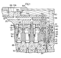
- Figure 1 shows part of a multi-cavity injection molding system having a number of heated nozzles 10, each seated in a well 12 in a cavity plate 14 and a support plate 16.
- the melt passage 18 branches in a conventional elongated manifold 20 to a number of sub-manifolds 22 according to the invention which are mounted between the manifold 20 and the nozzles 10.
- a manifold according to the invention could be mounted to receive melt directly from the molding machine rather than to act as a sub-manifold.
- the section of the right hand sub-manifold 22 is taken along line 1-1 in Figure 4 to show the melt passage 18 as it continues from the sub-manifold 22 through the central bore 24 of the nozzle 10.
- Each nozzle 10 has a rear face 26 which abuts against the sub-manifold 22 and a tapered nose portion 28 leading to a pointed tip 30 at the forward end.
- the pointed tip 30 is in alignment with a gate 32 extending through the cavity plate 14 to a cavity 34.
- the nozzle 10 is located in this position in the well 12 by a circumferential insulation bushing 36 sitting on a circumferential flange 38.
- the nozzle 10 also has a sealing and locating flange 40 which extends across an insulative air space 42 to abut against a cylindrical insulating ring 44, as described in the applicant's U.S. patent number 4,854,851 which issued August 8, 1989.
- Each nozzle 10 is heated by an electrical heating element 45 which extends from an external cold terminal 46 and has a portion 48 which extends into the nose portion 28 of the nozzle 10 as described in the applicant's U.S. patent number 4,865,535 which issued September 12, 1989.
- the cavity plate 14 is cooled by pumping cooling water through cooling conduits 50.
- Each nozzle 10 is secured to a sub-manifold 22 by bolts 52.
- the sub-manifolds 22 are, in turn, secured to the support plate 16 by bolts 54.
- the elongated manifold 20 is positioned against the sub-manifolds 22 by a clamp plate 56 and titanium pressure pads 58.
- the clamp plate 56 is held in position by bolts 60 extending into the support plate 16.
- each sub-manifold 22 is attached to the elongated manifold 20 by bolts 62.
- a locating collar 64 extends around a manifold extension 66 which is fastened by bolts 68 to the manifold 20.
- the manifold 20 is heated by an electrical heating element 70 which is cast into it as described in the applicant's U.S. patent number 4,688,622 which issued August 25, 1987.
- the elongated manifold 20 is made with plugs 72 as described in detail in the applicant's U.S. patent number 4,609,138 referred to above.
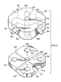
- a rear body portion 74 and a forward plate portion 76 are cast out of a suitable steel.
- the rear body portion 74 has a rear surface 78, a forward surface 80 and four outer surfaces 82. As seen in Figure 2, each of the outer surfaces 82 has a locating pin 84 extending outwardly therefrom.
- the forward surface 80 of the rear body portion 74 has a hollow locating portion 86 extending centrally therefrom. In this embodiment, the forward surface 80 also has four forwardly projecting collar portions 88.
- the rear body portion 74 is made by investment casting the steel on a removable ceramic mold which is shaped to provide a melt passage 90 having the critical shape shown in Figures 2 and 3.
- the melt passage 90 has a common inlet portion 92 which extends from a central inlet 94 on the rear surface 78.
- four outlet portions 96 branch outwardly from the common inlet portion 92.
- Each outlet portion 96 extends around a first smoothly curved bend 98, along a radial portion 100, and then around a second smoothly curved bend 102 to an outlet 103 through one of the collar portions 88.
- the shape of the melt passage 90 is critical to the successful operation of the injection molding system for some applications.
- the outlet portions 96 branch radially outward from the inlet portion 92 in more directions than two.
- the curved portions of the melt passage are not restricted to being in a single common plane. While there are four equally spaced outlet portions 96 in this embodiment, there can be three or more than four outlet portions for other mold configurations. It is important that the outlet portions be identical in length and size to avoid uneven pressure drop of the melt flowing through them.
- the bends 98,102 can be made very smoothly curved. This is extremely important for molding certain materials which are susceptible to stress at higher flow velocities.
- each outlet portion 96 is made to angle a substantial distance rearwardly as it extends outwardly from the first bend 98 to the second bend 102. This allows the overall thickness of the sub-manifold 22 to be reduced which can be very important for some applications.
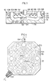
- the forward plate portion 76 is cast of steel to match the size of the rear body portion 74.
- the forward plate portion 76 has a central hole 104 therethrough to receive the central locating pin 86 of the rear body portion 74.
- the forward plate portion 76 also has four spaced holes 106 therethrough to receive the collar portions 88 which project forwardly from the rear body portion 74.
- the forward face 108 of the forward plate portion 76 also has a forwardly projecting outer rim 110 and four forwardly projecting partition portions 112 to form four equal sized recessed compartments 114. A number of spaced small ducts 116 extend from each of these compartments 114 through the forward plate portion 76.
- the forward surface 80 of the rear body portion 74 is made with a groove 118 which extends in a predetermined pattern, as seen in Figure 4.
- An electrical heating element 120 is wound in this groove 118 and extends to an external cold terminal 122.
- the heating element 120 has a conventional structure with a nickel-chromium resistance wire 124 extending centrally through a refractory powder electrical insulating material such as magnesium oxide inside a steel casing 126.
- the forward plate portion 76 is then mounted on the rear body portion 74 in the inverted position shown in Figure 3.
- An equal amount of a nickel alloy brazing powder is then poured into each compartment 114 and the assembly is heated in a vacuum furnace.
- the furnace is evacuated to a relatively high vacuum to remove substantially all of the oxygen.
- the vacuum is reduced by partially backfilling with an inert gas such as nitrogen or argon.
- an inert gas such as nitrogen or argon.
- the rear body portion 74 and the forward plate portion are integrally brazed together, with the heating element 120 integrally brazed in the groove 118. Brazing them in a vacuum provides a metallurgical bonding of the nickel alloy which improves the efficiency of the heat transfer from the heating element 120 to the surrounding steel.
- the sub-manifolds 22 are removed from the vacuum furnace and cooled, they are machined to remove the outer rim 110 and partition portions 112 to provide a smooth forward surface 128 with the central locating portion 86 extending therefrom. As seen in Figure 1, this locating portion 86 is received in a seat 130 in the support plate 16 to accurately locate the sub-manifold 22 relative thereto. Depending upon the mold configuration and the desired orientation of the sub-manifold 22, a selected three of the four outwardly projecting locating pins 84 are also machined off prior to assembly. As also seen in Figure 1, the remaining pin 84 is received in a slot 132 in the support plate 16 to rotationally locate the sub-manifold 22 relative thereto. The sub-manifolds are drilled to provide bolt holes 134 therethrough, as seen in Figure 4.
- Each outlet 103 from a sub-manifold 22 is aligned with the central melt bore 24 of a nozzle 10 through which the pressurized melt flows into a space 136 surrounding the nose portion 28, and then through the gate 32 to fill the cavity 34.
- the space 136 remains filled with melt, a portion of which solidifies adjacent the cooled cavity plate 14, and the sealing and locating flange 40 prevents it escaping into the insulative air space 42.
Landscapes
- Engineering & Computer Science (AREA)
- Manufacturing & Machinery (AREA)
- Mechanical Engineering (AREA)
- Moulds For Moulding Plastics Or The Like (AREA)
- Injection Moulding Of Plastics Or The Like (AREA)
Applications Claiming Priority (2)
| Application Number | Priority Date | Filing Date | Title |
|---|---|---|---|
| CA2017055 | 1990-05-17 | ||
| CA 2017055 CA2017055A1 (en) | 1990-05-17 | 1990-05-17 | Injection molding cast manifold |
Publications (2)
| Publication Number | Publication Date |
|---|---|
| EP0457166A2 true EP0457166A2 (de) | 1991-11-21 |
| EP0457166A3 EP0457166A3 (en) | 1992-05-06 |
Family
ID=4145011
Family Applications (1)
| Application Number | Title | Priority Date | Filing Date |
|---|---|---|---|
| EP19910107436 Withdrawn EP0457166A3 (en) | 1990-05-17 | 1991-05-07 | Injection molding cast manifold |
Country Status (5)
| Country | Link |
|---|---|
| EP (1) | EP0457166A3 (de) |
| JP (1) | JPH04232010A (de) |
| CN (1) | CN1056459A (de) |
| CA (1) | CA2017055A1 (de) |
| DE (1) | DE4114932A1 (de) |
Cited By (6)
| Publication number | Priority date | Publication date | Assignee | Title |
|---|---|---|---|---|
| EP0491332A2 (de) * | 1990-12-19 | 1992-06-24 | Mold-Masters Limited | Schmelzeverteilerblock für mehrere Formhöhlungen |
| US5227181A (en) * | 1990-12-19 | 1993-07-13 | Mold-Masters Limited | Multi-cavity melt distribution manifold |
| WO1996038284A1 (fr) * | 1995-05-30 | 1996-12-05 | Atek Developpement | Ensemble d'injection pour un moule d'injection de matiere plastique ainsi qu'un procede de realisation d'un tel ensemble |
| FR2734755A1 (fr) * | 1995-05-30 | 1996-12-06 | Atek Dev | Ensemble d'injection pour un moule d'injection de matiere plastique ainsi qu'un procede de realisation d'un tel ensemble |
| EP2205419A1 (de) * | 2007-11-03 | 2010-07-14 | MHT Mold & Hotrunner Technology AG | Angussadapter sowie angusssystem für einen angussadapter |
| CN105946184A (zh) * | 2016-06-24 | 2016-09-21 | 广州新晖汽车零部件有限公司 | 一种注塑模具的浇注系统 |
Families Citing this family (4)
| Publication number | Priority date | Publication date | Assignee | Title |
|---|---|---|---|---|
| US5142126A (en) * | 1991-07-08 | 1992-08-25 | Mold-Masters Limited | Injection molding manifold with integral heated inlet portion |
| DE19606806C2 (de) * | 1996-02-23 | 1998-01-22 | Kurt Dipl Ing Detering | Vorrichtung zum Thixoforming |
| DE29615042U1 (de) * | 1996-08-29 | 1996-10-24 | Schmale & Schulte Gmbh | System eines Mehrfachfertigungswerkzeuges für Zink- und Magnesiumdruckguß sowie Kunststoff-Spritzguß |
| JP4515075B2 (ja) * | 2003-11-07 | 2010-07-28 | 株式会社デンソー | 内燃機関用スロットル装置の射出成形方法 |
Citations (3)
| Publication number | Priority date | Publication date | Assignee | Title |
|---|---|---|---|---|
| US4256140A (en) * | 1979-12-06 | 1981-03-17 | The Continental Group, Inc. | Two-piece hot runner manifold |
| US4648546A (en) * | 1985-04-09 | 1987-03-10 | Gellert Jobst U | Composite plate method of manufacturing injection molding manifold |
| DE3906651A1 (de) * | 1989-03-02 | 1990-09-06 | Hans Schreck | Heisskanal fuer eine kunststoffspritzmaschine |
-
1990
- 1990-05-17 CA CA 2017055 patent/CA2017055A1/en not_active Abandoned
-
1991
- 1991-05-07 DE DE19914114932 patent/DE4114932A1/de not_active Withdrawn
- 1991-05-07 EP EP19910107436 patent/EP0457166A3/en not_active Withdrawn
- 1991-05-15 CN CN 91103010 patent/CN1056459A/zh active Pending
- 1991-05-17 JP JP14117591A patent/JPH04232010A/ja active Pending
Patent Citations (3)
| Publication number | Priority date | Publication date | Assignee | Title |
|---|---|---|---|---|
| US4256140A (en) * | 1979-12-06 | 1981-03-17 | The Continental Group, Inc. | Two-piece hot runner manifold |
| US4648546A (en) * | 1985-04-09 | 1987-03-10 | Gellert Jobst U | Composite plate method of manufacturing injection molding manifold |
| DE3906651A1 (de) * | 1989-03-02 | 1990-09-06 | Hans Schreck | Heisskanal fuer eine kunststoffspritzmaschine |
Cited By (10)
| Publication number | Priority date | Publication date | Assignee | Title |
|---|---|---|---|---|
| EP0491332A2 (de) * | 1990-12-19 | 1992-06-24 | Mold-Masters Limited | Schmelzeverteilerblock für mehrere Formhöhlungen |
| EP0491332A3 (en) * | 1990-12-19 | 1992-11-19 | Mold-Masters Limited | Multi-cavity melt distribution manifold |
| US5227181A (en) * | 1990-12-19 | 1993-07-13 | Mold-Masters Limited | Multi-cavity melt distribution manifold |
| WO1996038284A1 (fr) * | 1995-05-30 | 1996-12-05 | Atek Developpement | Ensemble d'injection pour un moule d'injection de matiere plastique ainsi qu'un procede de realisation d'un tel ensemble |
| FR2734755A1 (fr) * | 1995-05-30 | 1996-12-06 | Atek Dev | Ensemble d'injection pour un moule d'injection de matiere plastique ainsi qu'un procede de realisation d'un tel ensemble |
| FR2734756A1 (fr) * | 1995-05-30 | 1996-12-06 | Atek Dev | Ensemble d'injection pour un moule d'injection de matiere plastique ainsi qu'un procede de realisation d'un tel ensemble |
| US6079971A (en) * | 1995-05-30 | 2000-06-27 | L.M.R. | Injection assembly for a plastic injection mould and method for making the assembly |
| EP2205419A1 (de) * | 2007-11-03 | 2010-07-14 | MHT Mold & Hotrunner Technology AG | Angussadapter sowie angusssystem für einen angussadapter |
| CN105946184A (zh) * | 2016-06-24 | 2016-09-21 | 广州新晖汽车零部件有限公司 | 一种注塑模具的浇注系统 |
| CN105946184B (zh) * | 2016-06-24 | 2018-11-16 | 广州新晖汽车零部件有限公司 | 一种注塑模具的浇注系统 |
Also Published As
| Publication number | Publication date |
|---|---|
| EP0457166A3 (en) | 1992-05-06 |
| CN1056459A (zh) | 1991-11-27 |
| JPH04232010A (ja) | 1992-08-20 |
| DE4114932A1 (de) | 1991-11-21 |
| CA2017055A1 (en) | 1991-11-17 |
Similar Documents
| Publication | Publication Date | Title |
|---|---|---|
| US4945630A (en) | Method of making a selected size injection molding nozzle | |
| US5096411A (en) | Injection molding cast manifold | |
| US6017209A (en) | Injection molding cooled gate insert | |
| US4663811A (en) | Manufacturing method for selected gate configuration injection molding nozzles | |
| US6030202A (en) | Injection molding three portion gate and cavity insert | |
| US6176700B1 (en) | Injection molding cooled cavity insert | |
| US6009616A (en) | Method of making an injection molding nozzle with tip insert | |
| US5652003A (en) | Injection molding nozzle with radial vanes | |
| US5441197A (en) | Method of manufacturing injection molding manifold having a melt passage with an elbow | |
| US4820147A (en) | Injection molding elongated probe having integral heating element and locating means | |
| US5496168A (en) | Injection molding manifold having a heating element extending between the plates | |
| CA2030287C (en) | Injection molding apparatus having separate heating element in the cavity forming insert | |
| EP0457166A2 (de) | Gegossener Spritzgiessverteiler | |
| US5217730A (en) | Multi-cavity injection molding heated nozzle | |
| CA2138353C (en) | Method of manufacturing injection molding manifold having a melt passage with an elbow | |
| EP0855261B1 (de) | Spritzgiessvorrichtung mit gekühltem Kern | |
| US5935621A (en) | Injection molding apparatus having a cooled core | |
| US5142126A (en) | Injection molding manifold with integral heated inlet portion | |
| EP0518120B1 (de) | Spritzgussverteilerblock mit einem einheitlichen, beheizten Zuführteil | |
| USRE38265E1 (en) | Injection molding apparatus having a cooled core | |
| CA2032728A1 (en) | Injection molding probe with varying heat profile | |
| CA1314370C (en) | Injection molding system having fluid cooled inserts | |
| CA2064677C (en) | Multi-cavity injection molding heated nozzle | |
| CA2195907A1 (en) | Injection molding apparatus with cooled core |
Legal Events
| Date | Code | Title | Description |
|---|---|---|---|
| PUAI | Public reference made under article 153(3) epc to a published international application that has entered the european phase |
Free format text: ORIGINAL CODE: 0009012 |
|
| AK | Designated contracting states |
Kind code of ref document: A2 Designated state(s): AT BE CH DE DK ES FR GB GR IT LI LU NL SE |
|
| PUAL | Search report despatched |
Free format text: ORIGINAL CODE: 0009013 |
|
| AK | Designated contracting states |
Kind code of ref document: A3 Designated state(s): AT BE CH DE DK ES FR GB GR IT LI LU NL SE |
|
| STAA | Information on the status of an ep patent application or granted ep patent |
Free format text: STATUS: THE APPLICATION IS DEEMED TO BE WITHDRAWN |
|
| 18D | Application deemed to be withdrawn |
Effective date: 19921107 |