EP0457094A1 - Device for connecting a flat ventilation plate inside a container - Google Patents
Device for connecting a flat ventilation plate inside a container Download PDFInfo
- Publication number
- EP0457094A1 EP0457094A1 EP91106986A EP91106986A EP0457094A1 EP 0457094 A1 EP0457094 A1 EP 0457094A1 EP 91106986 A EP91106986 A EP 91106986A EP 91106986 A EP91106986 A EP 91106986A EP 0457094 A1 EP0457094 A1 EP 0457094A1
- Authority
- EP
- European Patent Office
- Prior art keywords
- aerator
- plate
- intermediate piece
- tank
- sleeve
- Prior art date
- Legal status (The legal status is an assumption and is not a legal conclusion. Google has not performed a legal analysis and makes no representation as to the accuracy of the status listed.)
- Granted
Links
Images

Classifications
-
- B—PERFORMING OPERATIONS; TRANSPORTING
- B65—CONVEYING; PACKING; STORING; HANDLING THIN OR FILAMENTARY MATERIAL
- B65D—CONTAINERS FOR STORAGE OR TRANSPORT OF ARTICLES OR MATERIALS, e.g. BAGS, BARRELS, BOTTLES, BOXES, CANS, CARTONS, CRATES, DRUMS, JARS, TANKS, HOPPERS, FORWARDING CONTAINERS; ACCESSORIES, CLOSURES, OR FITTINGS THEREFOR; PACKAGING ELEMENTS; PACKAGES
- B65D88/00—Large containers
- B65D88/74—Large containers having means for heating, cooling, aerating or other conditioning of contents
- B65D88/745—Large containers having means for heating, cooling, aerating or other conditioning of contents blowing or injecting heating, cooling or other conditioning fluid inside the container
-
- B—PERFORMING OPERATIONS; TRANSPORTING
- B01—PHYSICAL OR CHEMICAL PROCESSES OR APPARATUS IN GENERAL
- B01F—MIXING, e.g. DISSOLVING, EMULSIFYING OR DISPERSING
- B01F23/00—Mixing according to the phases to be mixed, e.g. dispersing or emulsifying
- B01F23/20—Mixing gases with liquids
- B01F23/23—Mixing gases with liquids by introducing gases into liquid media, e.g. for producing aerated liquids
- B01F23/231—Mixing gases with liquids by introducing gases into liquid media, e.g. for producing aerated liquids by bubbling
- B01F23/23105—Arrangement or manipulation of the gas bubbling devices
- B01F23/2311—Mounting the bubbling devices or the diffusers
- B01F23/23114—Mounting the bubbling devices or the diffusers characterised by the way in which the different elements of the bubbling installation are mounted
- B01F23/231143—Mounting the bubbling elements or diffusors, e.g. on conduits, using connecting elements; Connections therefor
-
- B—PERFORMING OPERATIONS; TRANSPORTING
- B01—PHYSICAL OR CHEMICAL PROCESSES OR APPARATUS IN GENERAL
- B01F—MIXING, e.g. DISSOLVING, EMULSIFYING OR DISPERSING
- B01F23/00—Mixing according to the phases to be mixed, e.g. dispersing or emulsifying
- B01F23/20—Mixing gases with liquids
- B01F23/23—Mixing gases with liquids by introducing gases into liquid media, e.g. for producing aerated liquids
- B01F23/231—Mixing gases with liquids by introducing gases into liquid media, e.g. for producing aerated liquids by bubbling
- B01F23/23105—Arrangement or manipulation of the gas bubbling devices
- B01F23/2312—Diffusers
- B01F23/23126—Diffusers characterised by the shape of the diffuser element
- B01F23/231261—Diffusers characterised by the shape of the diffuser element having a box- or block-shape, being in the form of aeration stones
-
- C—CHEMISTRY; METALLURGY
- C02—TREATMENT OF WATER, WASTE WATER, SEWAGE, OR SLUDGE
- C02F—TREATMENT OF WATER, WASTE WATER, SEWAGE, OR SLUDGE
- C02F3/00—Biological treatment of water, waste water, or sewage
- C02F3/02—Aerobic processes
- C02F3/12—Activated sludge processes
- C02F3/20—Activated sludge processes using diffusers
- C02F3/201—Perforated, resilient plastic diffusers, e.g. membranes, sheets, foils, tubes, hoses
-
- Y—GENERAL TAGGING OF NEW TECHNOLOGICAL DEVELOPMENTS; GENERAL TAGGING OF CROSS-SECTIONAL TECHNOLOGIES SPANNING OVER SEVERAL SECTIONS OF THE IPC; TECHNICAL SUBJECTS COVERED BY FORMER USPC CROSS-REFERENCE ART COLLECTIONS [XRACs] AND DIGESTS
- Y02—TECHNOLOGIES OR APPLICATIONS FOR MITIGATION OR ADAPTATION AGAINST CLIMATE CHANGE
- Y02W—CLIMATE CHANGE MITIGATION TECHNOLOGIES RELATED TO WASTEWATER TREATMENT OR WASTE MANAGEMENT
- Y02W10/00—Technologies for wastewater treatment
- Y02W10/10—Biological treatment of water, waste water, or sewage
Definitions
- the invention relates to a device for connecting a flat aerator plate to the bottom plate of the tank, which is provided with an internally threaded sleeve and is arranged in the middle of the surface of the back and is arranged inside a tank.
- Such aerator plates generally have the shape of an elongated rectangle and have on their upper side a multiplicity of holes or nozzles from which gas, for example air, bubbles for the aeration of liquids.
- the aerator plates are connected to the sturdy, installed, square-shaped aerator tubes with the top side with the nozzles facing upwards and also fastened.
- the sleeve is used for connection and fastening.
- an externally threaded nipple is provided in the upward-facing connecting wall of the aerator tube for each aerator plate, onto which the relevant aerator plate is screwed with its sleeve.
- the aerator plate must be rotated around the axis of the sleeve.
- enough space must be left free on both sides for each aerator plate so that the rotary movement can be carried out. This in turn hinders a tight arrangement of the aerator plates, which may be desirable.
- the object of the invention is to design a device of the type mentioned in such a way that the aerator plates can also be arranged very closely next to one another and closely next to the side walls and other internals within a tank.
- the invention is characterized in that a tubular intermediate piece is provided which has an annular projection in the longitudinal center and shoulders perpendicular to the longitudinal axis on both sides, that one end of the intermediate piece has a first external thread which fits into the internal thread of the sleeve, and that the other end of the Intermediate piece has a second external thread and fits through a smooth connection hole provided with a protrusion in the base plate, that the protrusion has a connecting sleeve, preferably a hose nipple, and that a nut is provided, which can be screwed onto the protrusion by tightening the base plate against the projection.
- the invention is preferably applicable to the arrangement of the aerator plates within a tank, but is not limited to this application.
- the aerator plate can remain in its later swivel position during assembly, so it does not require a free swivel space for assembly. This in turn makes it possible that the aerator plates can also be arranged in tight spaces without additional pivoting.
- the invention is also easy to implement. It does not require a threaded nipple in the tank bottom, a simple, smooth connection hole is sufficient. Only the intermediate piece is required in addition, a small part, the additional expenditure of which is achieved simply by the relief that can be achieved with the invention assembly is justified, quite apart from the expansion of the arrangement options.
- the desired seal is favored by the fact that a sealing ring is provided which is plugged onto the other end of the intermediate piece and is arranged between the projection of the intermediate piece and the base plate.
- the assembly is further facilitated if the projection of the intermediate piece is designed as a hexagon on the outside.
- the invention is advantageously applicable to an aerator device with a plurality of aerator plates, which are arranged in a common tank with devices according to the invention.
- an aerator plate can be arranged within the pivoting range of an adjacent aerator plate, the pivoting range being defined by the largest circle which the aerator plate in question describes when rotating about the axis of its sleeve.
- the application of the invention is not restricted to such aerator devices.
- a smooth connection hole 3 is provided in the horizontal base plate 1 of a liquid tank 2 which is only partially visible.
- the intermediate piece 4 is tubular and has in its longitudinal center an annular projection 5 which can be designed as an outside as a hexagon, but in the exemplary embodiment is round on the outside and can be gripped for assembly with a pipe wrench. Shoulders 8, 9 perpendicular to the longitudinal axis 7 are provided on both sides of the projection 5.
- One end 10 of the intermediate piece is provided with a first external thread 11. This first external thread 11 fits into the internal thread 12 of a sleeve 13 which is arranged in the center of the surface of the underside of the base plate 14 of an aerator plate, generally designated 18.
- the aerator plate 18 consists of two plane-parallel, spaced-apart rectangular plates - the base plate 14 and the cover plate 15 - and a peripheral edge 16, so that a cuboid box is formed.
- the sleeve 13 opens into the interior 17 of the aerator plate 18.
- aerator nozzles for example the aerator nozzles 19, 20, 21, are provided over the entire surface.
- Pressurized gas which flows from the intermediate piece 4 through the sleeve 13 into the interior 17 of the aerator plate 18, then flows upward from these aerator nozzles, for example into the liquid filled in the tank 2, which is to be aerated by the gas, for example.
- the interior 17 of the aerator plate 18, apart from the connection of the sleeve 13 and the aerator nozzles, is closed in a pressure-tight and gas-tight manner.
- the other end 25 of the intermediate piece 4 has a second external thread 26, fits with play through the connection hole 3 and protrudes from the base plate 1 with a projection 27.
- a sealing ring 28 made of elastic material.
- a nut 29 is screwed with an external hexagon and tightened so that the intermediate piece, sealed by the sealing ring 28, sits firmly in the base plate 1, the base plate 1 is thus clamped between the shoulder 9 and the nut 29.
- the outermost free end of the intermediate piece 4 is designed as a hose nipple 30. It is thus possible to connect a pressure gas hose to the hose nipple 30, through the pressure gas through the channel 31 of the intermediate piece, through the channel 32 of the sleeve, through an opening 33 in the base plate 14 into the interior 17 of the aerator plate 18 and from there through the aerator nozzles 19, 20, 21 ... flows into the liquid in tank 2.
- a threaded nipple can also be provided.
- the intermediate piece 4 is first screwed tight into the sleeve 13, then the end 25 of the intermediate piece 4 is inserted with the interposition of the sealing ring 28 into the connection hole 3 and the aerator plate is held in the angular orientation to the axis 7, which it is finally in assembled state. Then the nut 29 is screwed on and tightened. The expansion is reversed accordingly.
- the aerator plate 18 does not have to be rotated about its axis 7 neither during installation nor during removal.
- These aerator plates since they generally have an elongated, rectangular cross section, have a very large pivoting radius when rotated about their axis, as indicated for example by the dash-dot circle 40 for the aerator plate 18 in FIG. Since, according to the invention, the aerator plate does not have to be rotated during assembly and disassembly, a very close arrangement of the aerator plates next to one another, as is shown for example for the aerator plates 41, 42, 18 and 44 in FIG. 3, is possible.
- aerator plates are arranged at the same height so close to one another on the common base plate 1 within the common tank 2 that the aerator plate 42 protrudes into the swivel range of the adjacent aerator plate 18, which is shown by the dot-dash circle 40.
- the aerator plate 41 could not have been arranged as shown in FIG. 3 if pivoting movements of the aerator plate 41 about its axis were required for assembly.
Abstract
Description
Die Erfindung betrifft eine Vorrichtung zum Anschluß einer flachen, mit einem in der Flächenmitte der Rückseite angeordneten, mit Innengewinde versehenen Muffe ausgestatteten, innerhalb eines Tanks angeordneten Belüfterplatte an der Bodenplatte des Tanks.The invention relates to a device for connecting a flat aerator plate to the bottom plate of the tank, which is provided with an internally threaded sleeve and is arranged in the middle of the surface of the back and is arranged inside a tank.
Solche Belüfterplatten haben im allgemeinen die Form eines langgestreckten Rechtecks und weisen auf ihrer Oberseite eine Vielzahl von Löchern oder Düsen auf, aus denen zur Belüftung von Flüssigkeiten Gas, beispielsweise Luft, perlt. Die Belüfterplatten werden zu diesem Zweck mit der mit den Düsen ausgestatteten Oberseite nach oben weisend an stabilen, verlegten, vierkantigen Belüfterrohren angeschlossen und auch befestigt. Zum Anschluß und zur Befestigung dient die Muffe.Such aerator plates generally have the shape of an elongated rectangle and have on their upper side a multiplicity of holes or nozzles from which gas, for example air, bubbles for the aeration of liquids. For this purpose, the aerator plates are connected to the sturdy, installed, square-shaped aerator tubes with the top side with the nozzles facing upwards and also fastened. The sleeve is used for connection and fastening.
Bei einer bekannten Belüftungsanlage ist in der nach oben weisenden Anschlußwand des Belüfterrohrs für jede Belüfterplatte ein mit Außengewinde versehener Nippel vorgesehen, auf den die betreffende Belüfterplatte mit ihrer Muffe geschraubt wird. Dazu muß die Belüfterplatte um die Achse der Muffe gedreht werden. Das hat zur Folge, daß man für jede Belüfterplatte genügend Platz nach beiden Seiten freihalten muß, damit die Drehbewegung durchgeführt werden kann. Das wiederum behindert eine unter Umständen wünschenswerte enge Anordnung der Belüfterplatten.In a known ventilation system, an externally threaded nipple is provided in the upward-facing connecting wall of the aerator tube for each aerator plate, onto which the relevant aerator plate is screwed with its sleeve. To do this, the aerator plate must be rotated around the axis of the sleeve. As a result, enough space must be left free on both sides for each aerator plate so that the rotary movement can be carried out. This in turn hinders a tight arrangement of the aerator plates, which may be desirable.
Im Inneren eines Tanks ist die Notwendigkeit, die Belüfterplatte bei der Montage zu schwenken, zusätzlich besonders hinderlich wegen der den Schwenkbereich einschränkenden Tankwände und weiterer möglicher Tankeinbauten.Inside a tank, the need to swivel the aerator plate during assembly is particularly cumbersome because of the tank walls that restrict the swivel range and other possible tank internals.
Aufgabe der Erfindung ist es, eine Vorrichtung der eingangs genannten Art so auszugestalten, daß sich die Belüfterplatten auch sehr eng nebeneinander und eng neben den Seitenwänden und anderen Einbauten innerhalb eines Tanks anordnen lassen.The object of the invention is to design a device of the type mentioned in such a way that the aerator plates can also be arranged very closely next to one another and closely next to the side walls and other internals within a tank.
Die Erfindung ist dadurch gekennzeichnet, daß ein rohrförmiges Zwischenstück vorgesehen ist, das in der Längsmitte einen ringförmigen Vorsprung und beidseitig zur Längsachse senkrechte Schultern aufweist, daß das eine Ende des Zwischenstücks ein in das Innengewinde der Muffe passendes erstes Außengewinde aufweist, daß das andere Ende des Zwischenstücks ein zweites Außengewinde aufweist und durch ein in der Bodenplatte vorgesehenes, glattes Anschlußloch mit Überstand paßt, daß der Überstand eine Anschlußmuffe, vorzugsweise einen Schlauchnippel, aufweist und daß eine Mutter vorgesehen ist, die die Bodenplatte gegen den Vorsprung verspannend auf den Überstand aufschraubbar ist.The invention is characterized in that a tubular intermediate piece is provided which has an annular projection in the longitudinal center and shoulders perpendicular to the longitudinal axis on both sides, that one end of the intermediate piece has a first external thread which fits into the internal thread of the sleeve, and that the other end of the Intermediate piece has a second external thread and fits through a smooth connection hole provided with a protrusion in the base plate, that the protrusion has a connecting sleeve, preferably a hose nipple, and that a nut is provided, which can be screwed onto the protrusion by tightening the base plate against the projection.
Die Erfindung ist bevorzugt anwendbar bei der Anordnung der Belüfterplatten innerhalb eines Tanks, sie ist auf diese Anwendung aber nicht beschränkt.The invention is preferably applicable to the arrangement of the aerator plates within a tank, but is not limited to this application.
Nach der Erfindung kann während der Montage die Belüfterplatte in ihrer späteren Schwenkstellung verbleiben, benötigt also für die Montage keinen freien Schwenkraum. Das wiederum macht es möglich, daß die Belüfterplatten ohne zusätzlichen Schwenkbedarf auch in bedrängten Platzverhältnissen angeordnet werden können.According to the invention, the aerator plate can remain in its later swivel position during assembly, so it does not require a free swivel space for assembly. This in turn makes it possible that the aerator plates can also be arranged in tight spaces without additional pivoting.
Die Erfindung ist auch einfach zu verwirklichen. Sie erfordert im Tankboden keinen Gewindenippel, es genügt ein einfaches, glattes Anschlußloch. Es wird nur das Zwischenstück zusätzlich benötigt, ein Kleinteil, dessen Zusatzaufwand allein schon durch die mit der Erfindung erzielbare Erleichterung der Montage gerechtfertigt ist, ganz abgesehen von der Erweiterung der Anordnungsmöglichkeiten.The invention is also easy to implement. It does not require a threaded nipple in the tank bottom, a simple, smooth connection hole is sufficient. Only the intermediate piece is required in addition, a small part, the additional expenditure of which is achieved simply by the relief that can be achieved with the invention assembly is justified, quite apart from the expansion of the arrangement options.
Die angestrebte Dichtung wird dadurch begünstigt, daß ein Dichtungsring vorgesehen ist, der auf das andere Ende des Zwischenstücks gesteckt und zwischen dem Vorsprung des Zwischenstücks und der Bodenplatte angeordnet ist.The desired seal is favored by the fact that a sealing ring is provided which is plugged onto the other end of the intermediate piece and is arranged between the projection of the intermediate piece and the base plate.
Die Montage wird weiter erleichtert, wenn der Vorsprung des Zwischenstücks außen als Sechskant ausgebildet ist.The assembly is further facilitated if the projection of the intermediate piece is designed as a hexagon on the outside.
Die Erfindung ist vorteilhaft anwendbar bei einer Belüftereinrichtung mit mehreren Belüfterplatten, die mit Vorrichtungen nach der Erfindung in einem gemeinsamen Tank aufgereiht angeordnet sind. In einem solchen Fall kann eine Belüfterplatte innerhalb des Schwenkbereichs einer benachbarten Belüfterplatte angeordnet sein, wobei der Schwenkbereich definiert ist durch den größten Kreis, den die betreffende Belüfterplatte beim Drehen um die Achse ihrer Muffe beschreibt. Die Anwendung der Erfindung ist aber nicht auf solche Belüftereinrichtungen beschränkt.The invention is advantageously applicable to an aerator device with a plurality of aerator plates, which are arranged in a common tank with devices according to the invention. In such a case, an aerator plate can be arranged within the pivoting range of an adjacent aerator plate, the pivoting range being defined by the largest circle which the aerator plate in question describes when rotating about the axis of its sleeve. However, the application of the invention is not restricted to such aerator devices.
Die Erfindung wird nun anhand der beigefügten Zeichnung näher erläutert.The invention will now be explained in more detail with reference to the accompanying drawing.
In der Zeichnung zeigt:
- Figur 1
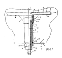
- im Teilquerschnitt eine Belüfterplatte, die innerhalb eines Tanks an den Tankboden angeschlossen ist,
- Figur 2
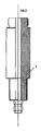
- das Zwischenstück aus Figur 1 im Teilschnitt und
- Figur 3
- in Draufsicht eine innerhalb eines Tanks angeordnete Belüftereinrichtung mit mehreren Belüfterplatten.
- Figure 1
- in partial cross-section an aerator plate which is connected to the tank bottom within a tank,
- Figure 2
- the intermediate piece of Figure 1 in partial section and
- Figure 3
- in plan view an aerator device arranged within a tank with several aerator plates.
In der horizontalen Bodenplatte 1 eines nur teilweise sichtbaren Flüssigkeitstanks 2 ist ein glattes Anschlußloch 3 vorgesehen. In diesem Anschlußloch 3 steckt ein Zwischenstück 4. Das Zwischenstück 4 ist rohrförmig und weist in seiner Längsmitte einen ringförmigen Vorsprung 5 auf, der als außen als Sechskant ausgebildet sein kann, im Ausführungsbeispiel aber außen rund ist und zur Montage mit einer Rohrzange gefaßt werden kann. Beidseitig des Vorsprungs 5 sind zur Längsachse 7 senkrechte Schultern 8, 9 vorgesehen. Das eine Ende 10 des Zwischenstücks ist mit einem ersten Außengewinde 11 versehen. Dieses erste Außengewinde 11 paßt in das Innengewinde 12 einer Muffe 13, die in der Flächenmitte der Unterseite der Bodenplatte 14 einer allgemein mit 18 bezeichneten Belüfterplatte angeordnet ist.A smooth connection hole 3 is provided in the horizontal base plate 1 of a liquid tank 2 which is only partially visible. In this connection hole 3 there is an
Die Belüfterplatte 18 besteht aus zwei planparallel mit Abstand zueinander angeordneten, rechteckigen Platten - der Bodenplatte 14 und der Deckplatte 15 - und einem umlaufenden Rand 16, so daß ein quaderförmiger Kasten entsteht. Die Muffe 13 mündet in das Innere 17 der Belüfterplatte 18. In der Deckplatte 15 sind auf die ganze Fläche verteilt Belüfterdüsen, zum Beispiel die Belüfterdüsen 19, 20, 21 vorgesehen. Druckgas, das aus dem Zwischenstück 4 durch die Muffe 13 in das Innere 17 der Belüfterplatte 18 strömt, strömt dann aus diesen Belüfterdüsen nach oben zum Beispiel in die in den Tank 2 eingefüllte Flüssigkeit, die durch das Gas beispielsweise belüftet werden soll. Das Innere 17 der Belüfterplatte 18 ist zu diesem Zweck, abgesehen von dem Anschluß der Muffe 13 und den Belüfterdüsen druck- und gasdicht abgeschlossen.The
Das andere Ende 25 des Zwischenstücks 4 weist ein zweites Außengewinde 26 auf, paßt mit Spiel durch das Anschlußloch 3 und ragt mit Überstand 27 aus der Bodenplatte 1 heraus. Zwischen der Schulter 9 und der Bodenplatte 1 liegt ein Dichtungsring 28 aus elastischem Material. Auf das Außengewinde 26 ist eine Mutter 29 mit äußerem Sechskant aufgeschraubt und festgezogen, so daß das Zwischenstück, abgedichtet durch den Dichtungsring 28, fest in der Bodenplatte 1 sitzt, die Bodenplatte 1 also zwischen der Schulter 9 und der Mutter 29 verspannt ist.The
Das äußerste freie Ende des Zwischenstücks 4 ist als Schlauchnippel 30 ausgebildet. So ist es möglich, an den Schlauchnippel 30 einen Druckgasschlauch anzuschließen, durch den Druckgas durch den Kanal 31 des Zwischenstücks, durch den Kanal 32 der Muffe, durch einen Durchbruch 33 der Bodenplatte 14 in das Innere 17 der Belüfterplatte 18 und von da durch die Belüfterdüsen 19, 20, 21 ... in die im Tank 2 vorhandene Flüssigkeit strömt. Anstelle des Schlauchnippel 30 kann auch ein Gewindenippel vorgesehen sein.The outermost free end of the
Zur Montage der Belüfterplatte 18 wird zunächst das Zwischenstück 4 stramm in die Muffe 13 geschraubt, dann wird das Ende 25 des Zwischenstücks 4 unter Zwischenlage des Dichtungsrings 28 in das Anschlußloch 3 gesteckt und die Belüfterplatte in der Winkelorientierung zur Achse 7 gehalten, die sie endgültig im montierten Zustand einnehmen soll. Dann wird die Mutter 29 aufgeschraubt und festgezogen. Der Ausbau erfolgt entsprechend umgekehrt.To assemble the
Bemerkenswert ist, daß weder beim Einbau noch beim Ausbau die Belüfterplatte 18 nicht um ihre Achse 7 gedreht werden muß. Diese Belüfterplatten haben, da sie im allgemeinen einen langgestreckten, rechteckigen Querschnitt haben, beim Drehen um ihre Achse, wie beispielsweise für die Belüfterplatte 18 in Figur 3 durch den strichpunktierten Kreis 40 angedeutet, einen sehr großen Schwenkradius. Da nach der Erfindung bei der Montage und Demontage die Belüfterplatte nicht gedreht werden muß, ist eine sehr enge Anordnung der Belüfterplatten nebeneinander, wie es beispielsweise für die Belüfterplatten 41, 42, 18 und 44 in Figur 3 dargestellt ist, möglich. Diese Belüfterplatten sind auf gleicher Höhe so dicht nebeneinander an der gemeinsamen Bodenplatte 1 innerhalb des gemeinsamen Tanks 2 angeordnet, daß die Belüfterplatte 42 in den durch die strichpunktierten Kreis 40 dargestellten Schwenkbereich der benachbarten Belüfterplatte 18 ragt. Die Belüfterplatte 41 hätte angesichts ihrer dichten Anordnung neben der Wand 45 des Tanks 2 nicht so angeordnet werden können wie in Figur 3 dargestellt, wenn zur Montage Schwenkbewegungen der Belüfterplatte 41 um ihre Achse erforderlich wären.It is noteworthy that the
Die in Figur 3 gezeichnete enge Anordnung wird erst durch die nach der Erfindung vorgesehene Anschlußvorrichtung möglich.The close arrangement shown in FIG. 3 is only possible through the connection device provided according to the invention.
Claims (5)
daß ein rohrförmiges Zwischenstück ( 4 ) vorgesehen ist, das in der Längsmitte einen ringförmigen Vorsprung ( 5 ) und beidseitig zur Längsachse ( 7 ) senkrechte Schultern ( 8, 9 ) aufweist,
daß das eine Ende ( 10 ) des Zwischenstücks ein in das Innengewinde ( 12 ) der Muffe ( 13 ) passendes erstes Außengewinde ( 11 ) aufweist,
daß das andere Ende ( 25 ) des Zwischenstücks ein zweites Außengewinde ( 26 ) aufweist und durch ein in der Bodenplatte ( 1 ) vorgesehenes, glattes Anschlußloch ( 3 ) mit Überstand ( 27 ) paßt,
daß der Überstand eine Anschlußmuffe ( 30 ) aufweist und
daß eine Mutter ( 29 ) vorgesehen ist, die die Bodenplatte gegen den Vorsprung ( 5 ) verspannend auf den Überstand aufschraubbar ist.Device for connecting a flat aerator plate to the base plate of the tank, which is provided with a sleeve which is arranged in the middle of the surface of the back, is provided with an internal thread, and is arranged within a tank,
that a tubular intermediate piece (4) is provided which has an annular projection (5) in the longitudinal center and shoulders (8, 9) perpendicular to the longitudinal axis (7) on both sides,
that one end (10) of the intermediate piece has a first external thread (11) which fits into the internal thread (12) of the sleeve (13),
that the other end (25) of the intermediate piece has a second external thread (26) and fits through a smooth connection hole (3) with a projection (27) provided in the base plate (1),
that the supernatant has a connecting sleeve (30) and
that a nut (29) is provided which can be screwed onto the protrusion by bracing the base plate against the projection (5).
daß ein Dichtungsring ( 28 ) vorgesehen ist, der auf das andere Ende ( 25 ) des Zwischenstücks ( 4 ) gesteckt und zwischen dem Vorsprung ( 5 ) des Zwischenstücks und der Bodenplatte ( 1 ) angeordnet ist.Device according to claim 1, characterized in
that a sealing ring (28) is provided which is placed on the other end (25) of the intermediate piece (4) and is arranged between the projection (5) of the intermediate piece and the base plate (1).
daß der Vorsprung ( 5 ) des Zwischenstücks ( 4 ) außen als Sechskant ausgebildet ist.Device according to claim 1 or 2, characterized in that
that the projection (5) of the intermediate piece (4) is formed on the outside as a hexagon.
daß die Anschlußmuffe ( 30 ) als Schlauchnippel oder als Gewindenippel ausgebildet ist.Device according to one of the preceding claims, characterized in that
that the connecting sleeve (30) is designed as a hose nipple or as a threaded nipple.
daß eine Belüfterplatte ( 42 ) innerhalb des Schwenkbereichs einer benachbarten Belüfterplatte ( 18 ) angeordnet ist, wobei der Schwenkbereich ( 40 ) definiert ist durch den größten Kreis, den die betreffende Belüfterplatte beim Drehen um die Achse ( 7 ) ihrer Muffe beschreibt.Aerator device with a plurality of aerator plates, which are arranged in a common tank with devices according to one of the preceding claims, characterized in that
that an aerator plate (42) is arranged within the pivoting range of an adjacent aerator plate (18), the pivoting range (40) being defined by the largest circle which the aerator plate in question describes when rotating about the axis (7) of its sleeve.
Applications Claiming Priority (2)
| Application Number | Priority Date | Filing Date | Title |
|---|---|---|---|
| DE9005422U | 1990-05-12 | ||
| DE9005422U DE9005422U1 (en) | 1990-05-12 | 1990-05-12 |
Publications (2)
| Publication Number | Publication Date |
|---|---|
| EP0457094A1 true EP0457094A1 (en) | 1991-11-21 |
| EP0457094B1 EP0457094B1 (en) | 1994-07-20 |
Family
ID=6853754
Family Applications (1)
| Application Number | Title | Priority Date | Filing Date |
|---|---|---|---|
| EP91106986A Expired - Lifetime EP0457094B1 (en) | 1990-05-12 | 1991-04-30 | Device for connecting a flat ventilation plate inside a container |
Country Status (3)
| Country | Link |
|---|---|
| EP (1) | EP0457094B1 (en) |
| AT (1) | ATE108696T1 (en) |
| DE (2) | DE9005422U1 (en) |
Families Citing this family (1)
| Publication number | Priority date | Publication date | Assignee | Title |
|---|---|---|---|---|
| DE9005422U1 (en) * | 1990-05-12 | 1990-07-19 | Egner, Siegfried, Dipl.-Ing., 6962 Adelsheim, De |
Citations (3)
| Publication number | Priority date | Publication date | Assignee | Title |
|---|---|---|---|---|
| GB824376A (en) * | 1956-12-19 | 1959-11-25 | Distillers Co Yeast Ltd | Gas liquid contacting means |
| GB2073602A (en) * | 1980-03-28 | 1981-10-21 | Farrer Activated Sludge Ltd W | Diffuser for aeration and agitation of liquid |
| DE9005422U1 (en) * | 1990-05-12 | 1990-07-19 | Egner, Siegfried, Dipl.-Ing., 6962 Adelsheim, De |
-
1990
- 1990-05-12 DE DE9005422U patent/DE9005422U1/de not_active Expired - Lifetime
-
1991
- 1991-04-30 AT AT91106986T patent/ATE108696T1/en active
- 1991-04-30 EP EP91106986A patent/EP0457094B1/en not_active Expired - Lifetime
- 1991-04-30 DE DE59102224T patent/DE59102224D1/en not_active Expired - Fee Related
Patent Citations (3)
| Publication number | Priority date | Publication date | Assignee | Title |
|---|---|---|---|---|
| GB824376A (en) * | 1956-12-19 | 1959-11-25 | Distillers Co Yeast Ltd | Gas liquid contacting means |
| GB2073602A (en) * | 1980-03-28 | 1981-10-21 | Farrer Activated Sludge Ltd W | Diffuser for aeration and agitation of liquid |
| DE9005422U1 (en) * | 1990-05-12 | 1990-07-19 | Egner, Siegfried, Dipl.-Ing., 6962 Adelsheim, De |
Also Published As
| Publication number | Publication date |
|---|---|
| DE59102224D1 (en) | 1994-08-25 |
| DE9005422U1 (en) | 1990-07-19 |
| ATE108696T1 (en) | 1994-08-15 |
| EP0457094B1 (en) | 1994-07-20 |
Similar Documents
| Publication | Publication Date | Title |
|---|---|---|
| DE3636882C1 (en) | Device for the fine-bubble introduction of a gas into a liquid | |
| CH671812A5 (en) | ||
| DE2313983A1 (en) | COUPLING DEVICE THAT CAN BE SWITCHED INTO A FLUID LINE FOR ACCEPTING AT LEAST ONE INFLUENCING DEVICE FOR THE FLUID | |
| DE1958112C3 (en) | ||
| DE1936782B2 (en) | Housing for a heat exchanger | |
| DE1922268A1 (en) | Filter system for separating suspended matter from an air or gas stream | |
| EP0234466B1 (en) | Diffuser for liquids, especially for oxygenation in clarification plants | |
| EP0482332B1 (en) | Process for injecting compressed air into a liquid | |
| EP0457094B1 (en) | Device for connecting a flat ventilation plate inside a container | |
| DE2335915C3 (en) | Device for holding and connecting devices connected in series for controlling and / or conditioning fluids | |
| DE19816322C2 (en) | Water meter connection and water meter unit | |
| DE4031164A1 (en) | Adaptor for connecting pipes to pump - includes system for aligning adaptor with pump housing | |
| EP0457095B1 (en) | Connection device of a plain ventilating plate | |
| DE69820506T2 (en) | Method for connecting floating bodies and the totality of floating bodies connected in this way | |
| DE3809016A1 (en) | Arrangement for introducing gas into liquids | |
| DE4447339C1 (en) | Ventilation system for a sewage biological filter | |
| DE4033814C2 (en) | ||
| DE2847968C3 (en) | Distribution or collection facility | |
| DE3812417C2 (en) | ||
| DE4020754A1 (en) | Heat exchanger for two liq. mediums - incorporates lip seal with flexible sealing lip | |
| DE102004018229B3 (en) | Fluid distribution device for assembly at a fluid supply device with a streaming direction parallel to a supply hole useful for water distribution systems | |
| EP0332157B1 (en) | Arrangement for joining a distribution device to a fluid supply conduit | |
| DE2941607A1 (en) | Reverse blasts of cleaning air for dust filter - are delivered from diaphragm valve fitted at top of storage unit | |
| DE3830688A1 (en) | Pressure filter | |
| DE1756046A1 (en) | Battery tank for liquids, especially for heating oil |
Legal Events
| Date | Code | Title | Description |
|---|---|---|---|
| PUAI | Public reference made under article 153(3) epc to a published international application that has entered the european phase |
Free format text: ORIGINAL CODE: 0009012 |
|
| AK | Designated contracting states |
Kind code of ref document: A1 Designated state(s): AT CH DE FR GB IT LI |
|
| 17P | Request for examination filed |
Effective date: 19911121 |
|
| 17Q | First examination report despatched |
Effective date: 19930706 |
|
| GRAA | (expected) grant |
Free format text: ORIGINAL CODE: 0009210 |
|
| AK | Designated contracting states |
Kind code of ref document: B1 Designated state(s): AT CH DE FR GB IT LI |
|
| REF | Corresponds to: |
Ref document number: 108696 Country of ref document: AT Date of ref document: 19940815 Kind code of ref document: T |
|
| REF | Corresponds to: |
Ref document number: 59102224 Country of ref document: DE Date of ref document: 19940825 |
|
| ITF | It: translation for a ep patent filed |
Owner name: DE DOMINICIS & MAYER S.R.L. |
|
| GBT | Gb: translation of ep patent filed (gb section 77(6)(a)/1977) |
Effective date: 19940906 |
|
| ET | Fr: translation filed | ||
| PGFP | Annual fee paid to national office [announced via postgrant information from national office to epo] |
Ref country code: GB Payment date: 19950411 Year of fee payment: 5 |
|
| PGFP | Annual fee paid to national office [announced via postgrant information from national office to epo] |
Ref country code: FR Payment date: 19950413 Year of fee payment: 5 |
|
| PGFP | Annual fee paid to national office [announced via postgrant information from national office to epo] |
Ref country code: AT Payment date: 19950420 Year of fee payment: 5 |
|
| PGFP | Annual fee paid to national office [announced via postgrant information from national office to epo] |
Ref country code: DE Payment date: 19950421 Year of fee payment: 5 |
|
| PGFP | Annual fee paid to national office [announced via postgrant information from national office to epo] |
Ref country code: CH Payment date: 19950519 Year of fee payment: 5 |
|
| PLBE | No opposition filed within time limit |
Free format text: ORIGINAL CODE: 0009261 |
|
| STAA | Information on the status of an ep patent application or granted ep patent |
Free format text: STATUS: NO OPPOSITION FILED WITHIN TIME LIMIT |
|
| 26N | No opposition filed | ||
| PG25 | Lapsed in a contracting state [announced via postgrant information from national office to epo] |
Ref country code: LI Effective date: 19960430 Ref country code: GB Effective date: 19960430 Ref country code: CH Effective date: 19960430 Ref country code: AT Effective date: 19960430 |
|
| REG | Reference to a national code |
Ref country code: CH Ref legal event code: PL |
|
| GBPC | Gb: european patent ceased through non-payment of renewal fee |
Effective date: 19960430 |
|
| PG25 | Lapsed in a contracting state [announced via postgrant information from national office to epo] |
Ref country code: FR Effective date: 19961227 |
|
| PG25 | Lapsed in a contracting state [announced via postgrant information from national office to epo] |
Ref country code: DE Effective date: 19970101 |
|
| REG | Reference to a national code |
Ref country code: FR Ref legal event code: ST |
|
| PG25 | Lapsed in a contracting state [announced via postgrant information from national office to epo] |
Ref country code: IT Free format text: LAPSE BECAUSE OF NON-PAYMENT OF DUE FEES;WARNING: LAPSES OF ITALIAN PATENTS WITH EFFECTIVE DATE BEFORE 2007 MAY HAVE OCCURRED AT ANY TIME BEFORE 2007. THE CORRECT EFFECTIVE DATE MAY BE DIFFERENT FROM THE ONE RECORDED. Effective date: 20050430 |