EP0457034B1 - Folding laundry drying rack - Google Patents
Folding laundry drying rack Download PDFInfo
- Publication number
- EP0457034B1 EP0457034B1 EP91105877A EP91105877A EP0457034B1 EP 0457034 B1 EP0457034 B1 EP 0457034B1 EP 91105877 A EP91105877 A EP 91105877A EP 91105877 A EP91105877 A EP 91105877A EP 0457034 B1 EP0457034 B1 EP 0457034B1
- Authority
- EP
- European Patent Office
- Prior art keywords
- laundry
- rod
- rods
- partial
- stand according
- Prior art date
- Legal status (The legal status is an assumption and is not a legal conclusion. Google has not performed a legal analysis and makes no representation as to the accuracy of the status listed.)
- Expired - Lifetime
Links
Images

Classifications
-
- D—TEXTILES; PAPER
- D06—TREATMENT OF TEXTILES OR THE LIKE; LAUNDERING; FLEXIBLE MATERIALS NOT OTHERWISE PROVIDED FOR
- D06F—LAUNDERING, DRYING, IRONING, PRESSING OR FOLDING TEXTILE ARTICLES
- D06F57/00—Supporting means, other than simple clothes-lines, for linen or garments to be dried or aired
- D06F57/08—Folding stands
Definitions
- the invention relates to a clothes horse according to the preamble of the first claim.
- Clothes racks in which the laundry is suspended on ropes or rods of an essentially horizontal drying rack are known in various designs.
- a clothes horse with a horizontally lying drying rack is known, which is supported on two intersecting supports. Two cross bars and a number of laundry bars that connect the cross bars together form the fixed drying rack.
- the supports have extension bars on the drying grate side, by means of which the height of the drying grate can be adjusted.
- a clothes horse which has a drying rack arranged on two intersecting supports, the cross bars of which are also connected to one another by clothes bars which are fastened to sleeves correspondingly pushed onto the cross bars and are thus displaceable in the direction of the cross bars .
- FR-A-1 272 258 describes a collapsible clothes horse with two supports which can be placed on the floor, which can be folded in and a fixed drying rack which has parallel laundry ropes or laundry bars attached to crossbars and a longitudinal bar which runs parallel to the laundry ropes or laundry bars, at the ends of which the Supports are pivoted and the cross bars are arranged.
- the above-described laundry racks have the disadvantage that the length of the laundry bars cannot be changed, so that items of laundry which are longer than the length of the laundry bars can only be hung up unfavorably and thus require a longer drying time.
- the invention is therefore based on the object of further developing a drying rack of the type described at the outset in such a way that even relatively large items of laundry can be hung up properly.
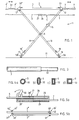
- the clothes horse 1 shown in FIGS. 1 and 2 has a drying grate 2, which is essentially composed of a longitudinal bar 3, two cross bars 4 and laundry bars 5, each laundry bar being composed of two partial bars 6, 7.
- a drying grate 2 which is essentially composed of a longitudinal bar 3, two cross bars 4 and laundry bars 5, each laundry bar being composed of two partial bars 6, 7.
- the laundry rods 5 are shown offset from the longitudinal rod 3 for better visibility. In reality, the laundry bars 5 are at approximately the same height as the longitudinal bar 3 and the transverse bars 4.
- the longitudinal bar 3 is supported on the floor 11 by means of two supports 9, 10 which intersect in a first joint piece 8. So that the clothes horse can be folded up, the supports 9, 10 are by means of transverse joints 12, 12 'with the longitudinal bar 3 connected, wherein in one of the supports 9 or 10 a further joint piece 15 is provided, by means of which the folding of the respective support and thus the complete folding of the supports 9, 10 and the application of the same to the drying rack 1 is made possible.
- the supports 9, 10 have telescopic legs 16, 17 that can be pulled out and pushed in again, by means of which height adjustment of the drying grate 1 is possible.
- the telescopic legs 16, 17 are fixed in their desired position by clamping elements 18, 18 ', for example by eccentric levers.
- the partial rod 6 is held in the upper bore 28, 28 ′ of the coupling block 26, while the partial rod 7 penetrates the bore 29 of the coupling block 26 and is firmly anchored in the bore 29 ′ of the coupling block 27 (not shown).
- the part rod 6 penetrates the bore 28 'of the coupling block 27 and is additionally provided with an eccentric lever 30 with which the part rod 6 and thus the coupling block 26 can be fixed in its position relative to the coupling block 27.
- the telescopic rods 32 can also be fixed, for which purpose corresponding clamping elements 33, for example at the ends of the longitudinal rod 3, as shown schematically in FIG. 1 and FIG. Clamping elements 33 or the like designed as eccentric levers are provided.
- 3 shows a section of the longitudinal rod 3 with the telescopic rod 32 arranged therein.
- FIGS. 4a, 4b, 4c and 4d corresponding variants of the tubular longitudinal rod 3 and of the telescopic rod 32 which is designed analogously to the longitudinal rod inner cross section are shown in the profile cross section.
- the length of the drying rack 1 is correspondingly increased in the longitudinal direction, so that large items of laundry can be hung up without problems.
- the clamping elements 18, 18 'are loosened the height of the drying rack 1 can also be raised by pulling out the telescopic legs 16, 17 and thus the standing length of the drying rack can be increased. This simultaneously ensures the required stability of the clothes horse 1 even when the telescopic rods 32 are extended.
- crossbar 4 is shown as an embodiment on one side in the normal position and in the extended position.
- the cross bars 4, 4 'are provided with corresponding extension bars 35, 36 which are also telescopically extendable and can be pushed together again.
- laundry rods 5 'are likewise provided and arranged accordingly, which are connected to one another by a telescopic rod, not shown.
- the extension bars 35, 36 can be designed in accordance with the design according to DE-B-2 286 265 or as a simple bar on which the laundry bars 5 are slidably arranged.
- the partial rods 6 ", 7" which essentially correspond to the partial rods 6 and 7, can also be designed as a tube, so that the coupling blocks 26 ', 27', as shown in FIG. 5b, are to be designed accordingly.
- the coupling blocks 26 ', 27' are provided with a end piece 40, 40 'bent to the partial rods 6 ", 7", which are widened to form a tab 41, 41' with a bore 42, 42 '.
- the coupling blocks 26 ', 27' can be firmly inserted with their end piece 40, 40 'into the bore of one sub-rod, the other sub-rod extending through the bore.
- the coupling blocks 26 ', 27' are shown in a not fully extended position.
- the coupling blocks 26 ', 27' do not lie snugly against one another, but are separated from one another by a distance (see also FIG. 2, in which only the crossbar 4 of one is pulled out Page is shown).
- the partial rods 6 ′′, 7 lie one above the other and form a reinforcement to prevent them from sagging when hanging up laundry.
- the reinforcement can be further improved by equipping one of the coupling blocks, as shown in FIG the corresponding coupling block is fixed in order to avoid displacement of the coupling blocks.
- FIG. 6 shows in view and FIG. 7 the joint piece 15 shown in section along the line VII-VII, which is correspondingly arranged on the support 9 (FIG. 1).
- the joint piece 15 essentially comprises two half-shells 50 and 51, which are connected by a connecting element, not shown, e.g. are held together by a screw with a nut.
- a pawl 53 loaded by a spring 52 is pivotably mounted with a pivot axis 54, which is arranged in a corresponding recess 55 in the other half-shell 51.
- the pawl 53 can be released from the notch-shaped recess 55 by a handle 56 protruding from the two half-shells 50, 51 for collapsing the clothes horse.
- the two half-shells 50, 51 form a housing with nozzles 60 and 60 ′ arranged opposite one another, each of which, as shown in FIG. 1, are operatively connected to the associated section of the support 9.
- the drying rack 1 described can be varied in that not only one longitudinal bar 3, but two and more longitudinal bars 3 are provided. Accordingly, the extendable cross bars 4,4 'can be provided with two or more telescopic bars.
- the partial rods 6, 7 can be made of different materials, e.g. B. made of steel, aluminum or reinforced plastic. However, it is also possible to use corresponding rope elements with coupling blocks instead of the partial rods 6, 7. If the one cross bar 4 or both cross bars 4 and 4 'are extended, they can be pushed together again. However, this option is not available when using a rope element.
- the cross bars 4, 4 'must be pulled out accordingly, but folding onto the undrawn surface of the drying rack 1 is possible. Since the partial rods 6, 7 are at least partially superimposed or stretched, the diameters of the partial rods 6, 7 can be relatively small, i.e. in the order of magnitude of 1 mm to 4 mm or larger.
- the bottom ends of the supports 9 and 10 or the ends of the telescopic legs 16, 17 can be provided with castors 58, 58 '.
- the supports 9 and 10 or the telescopic legs 16 and 17 are provided on the bottom side with a transverse foot (not shown), on the ends of which the rollers 58, 58 'can also be arranged.
Abstract
Description
Die Erfindung betrifft einen Wäscheständer gemäss dem Oberbegriff des ersten Patentanspruchs.The invention relates to a clothes horse according to the preamble of the first claim.
Wäscheständer, bei denen die Wäsche auf Seilen oder Stäben eines im wesentlichen horizontal liegenden Trocknungsrostes aufgehängt wird, sind in verschiedenen Ausführungen bekannt.Clothes racks in which the laundry is suspended on ropes or rods of an essentially horizontal drying rack are known in various designs.
Aus der DE-A-2234238 ist ein Wäscheständer mit einem horizontal liegenden Trocknungsrost bekannt, der an zwei sich kreuzenden Stützen abgestützt ist. Zwei Querstäbe und eine Anzahl Wäschestäbe, welche die Querstäbe miteinander verbinden, bilden den festen Trocknungsrost. Die Stützen weisen trocknungsrostseitig Verlängerungsstäbe auf, mittels welcher der Trocknungsrost höheneinstellbar ist.From DE-A-2234238 a clothes horse with a horizontally lying drying rack is known, which is supported on two intersecting supports. Two cross bars and a number of laundry bars that connect the cross bars together form the fixed drying rack. The supports have extension bars on the drying grate side, by means of which the height of the drying grate can be adjusted.
Aus der aus EP-A-0285913 ist ein Wäscheständer bekannt, welcher einen auf zwei sich kreuzenden Stützen angeordneten Trocknungsrost aufweist, dessen Querstäbe ebenfalls durch Wäschestäbe miteinander verbunden sind, die an entsprechend auf die Querstäbe geschobenen Hülsen befestigt und damit in Richtung der Querstäbe verschiebbar sind.From EP-A-0285913 a clothes horse is known which has a drying rack arranged on two intersecting supports, the cross bars of which are also connected to one another by clothes bars which are fastened to sleeves correspondingly pushed onto the cross bars and are thus displaceable in the direction of the cross bars .
Die FR-A-1 272 258 beschreibt einen zusammenklappbaren Wäscheständer mit zwei am Boden aufsetzbaren, einklappbaren Stützen und einem festen Trocknungsrost, welcher an Querstäben befestigte, parallele Wäscheseile oder Wäschestäbe und einen zu den Wäscheseilen oder Wäschestäben parallel verlaufenden Längsstab aufweist, an dessen Enden die Stützen schwenkbar angelenkt und die Querstäbe angeordnet sind.FR-A-1 272 258 describes a collapsible clothes horse with two supports which can be placed on the floor, which can be folded in and a fixed drying rack which has parallel laundry ropes or laundry bars attached to crossbars and a longitudinal bar which runs parallel to the laundry ropes or laundry bars, at the ends of which the Supports are pivoted and the cross bars are arranged.
Bei den vorstehend beschriebenen Wäscheständern besteht der Nachteil, dass die Länge der Wäschestäbe nicht geändert werden kann, so dass Wäschestücke, welche grösser als die Länge der Wäschestäbe sind, nur ungünstig aufgehängt werden können und somit eine längere Trocknungszeit benötigen.The above-described laundry racks have the disadvantage that the length of the laundry bars cannot be changed, so that items of laundry which are longer than the length of the laundry bars can only be hung up unfavorably and thus require a longer drying time.
Der Erfindung liegt somit die Aufgabe zugrunde, einen Wäscheständer der eingangs beschriebenen Art so weiter auszugestalten, dass auch relativ grosse Wäschestücke einwandfrei aufgehängt werden können.The invention is therefore based on the object of further developing a drying rack of the type described at the outset in such a way that even relatively large items of laundry can be hung up properly.
Diese Aufgabe wird gemäss der Erfindung durch die Merkmale des kennzeichnenden Teils des ersten Patentanspruchs gelöst.This object is achieved according to the invention by the features of the characterizing part of the first claim.
Da die einzelnen Wäscheseile oder Wäschestäbe aus zwei Teilen bestehen, wird erreicht, dass der eine Querstab oder auch beide Querstäbe so weit ausgezogen werden können, dass auch grosse Wäschestücke, die sonst nicht einfach aufgehängt werden könnten, problemlos aufgehängt werden können.Since the individual laundry ropes or laundry sticks consist of two parts, one of the cross bars or both cross bars can be pulled out to such an extent that even large items of laundry which otherwise could not simply be hung up can be hung up without problems.
Ein Ausführungsbeispiel der Erfindung ist in der Zeichnung dargestellt und nachfolgend beschrieben. Es zeigt:
- Fig.1
- einen in Seitenansicht dargestellten Wäscheständer mit einem in Richtung der Wäscheseile oder Wäschestäbe verlängerbaren Trocknungsrost;
- Fig.2
- das in Draufsicht dargestellte Trocknungsrost für den Wäscheständer gemäss Fig. 1;
- Fig.3
- einen im Detail dargestellten Längsstab für den Wäscheständer gemäss Fig. 1;
- Fig.4
- verschiedene, mit a);b);c) und d) bezeichnete Varianten des im Profilquerschnitt dargestellten und etwa teleskopartig ausgebildeten Längsstabes für den Wäscheständer gemäss Fig.1;
- Fig.5a
- ein in Schnittansicht dargestelltes Kupplungsstück für den Wäscheständer gemäss Fig.1;
- Fig.5b
- eine Variante eines Kupplungsstücks für den Wäscheständer gemäss Fig.1;
- Fig.6
- ein in Ansicht dargestelltes Gelenkstück für die Stützen zum Zusammenklappen des Wäscheständers; und
- Fig.7
- das in Schnittansicht dargestellte Gelenkstück gemäss der Linie VII-VII in Fig.6.
- Fig. 1
- a clothes rack shown in side view with a drying grate extendable in the direction of the laundry ropes or clothes rails;
- Fig. 2
- the drying rack shown in plan view for the clothes horse according to FIG. 1;
- Fig. 3
- a longitudinal rod shown in detail for the clothes horse according to FIG. 1;
- Fig. 4
- Various variants, designated a); b); c) and d), of the longitudinal bar for the clothes horse according to FIG.
- Fig.5a
- a sectional view of the coupling piece for the clothes horse according to Figure 1;
- Fig. 5b
- a variant of a coupling piece for the clothes horse according to Figure 1;
- Fig. 6
- a joint shown in view for the supports for folding the clothes rack; and
- Fig. 7
- the joint shown in the sectional view along the line VII-VII in Figure 6.
Der in Fig.1 und 2 dargestellte Wäscheständer 1 weist einen Trocknungsrost 2 auf, der im wesentlichen aus einem Längsstab 3, zwei Querstäben 4 und Wäschestäben 5 zusammengesetzt ist, wobei jeder Wäschestab aus zwei Teilstäben 6,7 zusammengesetzt ist. In Fig.1 sind die Wäschestäbe 5 mit Abstand zum Längsstab 3 zwecks besserer Erkennbarkeit versetzt angeordnet dargestellt. In Wirklichkeit liegen die Wäschestäbe 5 auf etwa derselben Höhe wie der Längsstab 3 und die Querstäbe 4.The clothes horse 1 shown in FIGS. 1 and 2 has a drying
Der Längsstab 3 ist mittels zwei sich in einem ersten Gelenkstück 8 kreuzenden Stützen 9,10 am Boden 11 abgestützt. Damit der Wäscheständer zusammengeklappt werden kann, sind die Stützen 9,10 mittels Quergelenke 12,12' mit dem Längsstab 3 verbunden, wobei in einer der Stützen 9 oder 10 ein weiteres Gelenkstück 15 vorgesehen ist, durch welches das Zusammenlegen der betreffenden Stütze und damit das vollständige Zusammenklappen der Stützen 9,10 und das Anlegen derselben an den Trocknungsrost 1 ermöglicht wird.The
Bodenseitig weisen die Stützen 9,10 auszieh- und wieder einschiebbare Teleskopbeine 16,17 auf, mittels welcher eine Höhenverstellung des Trocknungsrostes 1 möglich ist. Die Teleskopbeine 16,17 werden in der gewünschten Lage durch Klemmelemente 18,18', beispielsweise durch Exzenterhebel, in ihrer Lage fixiert.On the bottom side, the supports 9, 10 have
Jeweils zwei miteinander fluchtende Teilstäbe 6,7 sind mittels Kupplungsklötze 26,27 miteinander an ihren Enden verbunden. Die spezielle Ausbildung der Verbindung ist aus Fig.5a ersichtlich. Die Kupplungsklötze 26,27 sind je mit zwei Bohrungen 28,28' und 29,29' versehen. In den einen Bohrungen 28, 28' ist das eine Ende des Teilstabes 6 fest verankert, während der Teilstab 7 in den anderen Bohrungen 29,29' angeordnet ist.In each case two
In Fig.5a ist der Teilstab 6 in der oberen Bohrung 28,28' des Kupplungsklotzes 26 festgehalten, während der Teilstab 7 die Bohrung 29 des Kupplungsklotzes 26 durchdringt und in der Bohrung 29' des Kupplungsklotzes 27 fest verankert ist (nicht dargestellt). Entsprechend durchdringt der Teilstab 6 die Bohrung 28' des Kupplungsklotzes 27 und ist zusätzlich mit einem Exzenterhebel 30 versehen, mit welchem der Teilstab 6 und damit der Kupplungsklotz 26 in seiner Lage gegenüber dem Kupplungsklotz 27 fixiert werden kann. Diese besondere Ausbildung und Lagerung der Enden der Teilstäbe 6,7 wird im Zusammenhang mit der Ausziehbarkeit der Querstäbe 4 näher beschrieben.In FIG. 5 a, the
Aus Fig. 2 ist ersichtlich, dass der auf der rechten Figurenseite liegende Querstab 4 mittels eines Teleskopstabes oder Teleskoprohres 32 relativ zum Längsstab 3 ausziehbar ist. In gleicher Weise ist der auf der linken Figurenseite dargestellte Querstab 4' relativ zum Längsstab 3 ausziehbar. Werden beide Querstäbe 4,4' relativ zum Längsstab 3 vollständig ausgezogen, treffen sich jeweils die Kupplungsklötze 26,27 zweier gegenüberliegender Teilstäbe 6,7 in der in Fig.5a dargestellten Lage und liegen aneinander derart an, dass auch bei Belasten der Teilstäbe 6,7 keine Verlängerung und damit kein Durchhängen der Wäschestäbe 5 auftreten kann. Durch Klemmen mit dem Exzenterhebel 30 kann zudem die Lage der Kupplungsklötze 26,27 zueinander fixiert werden.From Fig. 2 it can be seen that the
Es ist zweckmässig, dass auch die Teleskopstäbe 32 fixierbar sind, wozu an den Enden des Längsstabes 3, wie in Fig.1 und Fig.2 schematisch dargestellt, entsprechende Klemmelemente 33, z.B. als Exzenterhebel ausgebildete Klemmelemente 33 oder dergleichen vorgesehen sind. In Fig.3 ist ein Teilstück des Längsstabes 3 mit dem darin angeordneten Teleskopstab 32 dargestellt.It is expedient that the
In den Figuren 4a,4b,4c und 4d sind im Profilquerschnitt entsprechende Varianten des rohrförmigen Längsstabes 3 sowie des entsprechend analog dem Längsstab-Innenquerschnitt ausgebildeten Teleskopstabes 32 dargestellt.In FIGS. 4a, 4b, 4c and 4d, corresponding variants of the tubular
Durch die Verlängerung des Trocknungsrostes durch Ausziehen der an den Teleskopstäben 32 befestigten Querstäbe 4 wird die Ausdehnung des Trocknungsrostes 1 in Längsrichtung entsprechend vergrössert, so dass grosse Wäschestücke problemlos aufgehängt werden können. Bei gelösten Klemmelementen 18,18' kann durch Herausziehen der Teleskopbeine 16,17 zudem die Höhe des Trocknungsrostes 1 angehoben und somit die Standlänge des Wäscheständers vergrössert werden. Hiermit wird gleichzeitig die erforderliche Standfestigkeit des Wäscheständers 1 auch bei ausgezogenen Teleskopstäben 32 gewährleistet.By extending the drying rack by pulling out the cross bars 4 attached to the
In Fig.2 ist als Ausführungsbeispiel der Querstab 4 auf der einen Seite in der Normalstellung sowie in der ausgezogenen Stellung dargestellt.In Figure 2, the
Weiterhin ist aus Fig.2 ersichtlich, dass es möglich ist, den Trocknungsrost 1 auch in seiner Breitenausdehnung zu vergrössern. Hierzu sind die Querstäbe 4,4' mit entsprechenden Verlängerungsstäben 35,36 versehen, die ebenfalls teleskopartig ausziehbar und wieder zusammenschiebbar ausgebildet sind. Zwischen den im Abstand zueinander angeordneten Verlängerungsstäben 35,36 sind ebenfalls Wäschestäben 5' vorgesehen und entsprechend angeordnet, welche durch einen nicht dargestellten Teleskopstab miteinander verbunden sind. Die Wäschestäbe 5' sind gleich ausgebildet wie die Wäschestäbe 5 und sind mit Teilstäben 6',7' und mit Kupplungsklötzen 26',27' versehen.It can also be seen from FIG. 2 that it is possible to enlarge the width of the drying grate 1. For this purpose, the cross bars 4, 4 'are provided with corresponding extension bars 35, 36 which are also telescopically extendable and can be pushed together again. Between the
Die Verlängerungsstäbe 35,36 können entsprechend der Ausführung gemäss der DE-B-2 286 265 oder aber als einfacher Stab ausgebildet sein, auf welchem die Wäschestäbe 5 verschiebbar angeordnet sind.The extension bars 35, 36 can be designed in accordance with the design according to DE-B-2 286 265 or as a simple bar on which the laundry bars 5 are slidably arranged.
Die Teilstäbe 6",7", welche im wesentlichen den Teilstäben 6 und 7 entsprechen, können auch als Rohr ausgebildet sein, so dass die Kupplungsklötze 26',27', wie in Fig.5b dargestellt, entsprechend auszubilden sind.The
Die Kupplungsklötze 26',27' sind mit einem zu den Teilstäben 6",7" abgebogenen Schlussstück 40,40' versehen, welche zu einem Lappen 41,41' mit einer Bohrung 42,42' verbreitert sind. Die Kupplungsklötze 26',27' können mit ihrem Schlussstück 40,40' in die Bohrung des einen Teilstabes fest eingesetzt werden, wobei sich durch die Bohrung der andere Teilstab ausstreckt.The coupling blocks 26 ', 27' are provided with a
In Fig.5b sind die Kupplungsklötze 26',27' in einer nicht voll ausgezogenen Stellung dargestellt. In diesem Fall liegen die Kupplungsklötze 26',27' nicht satt aneinander, sondern sind durch einen Abstand voneinander getrennt (siehe auch Fig.2, in welcher nur das Ausziehen des Querstabes 4 der einen Seite dargestellt ist). In diesem Bereich liegen die Teilstäbe 6",7 übereinander und bilden eine Verstärkung gegen das Durchbiegen beim Wäscheaufhängen. Die Verstärkung kann noch dadurch verbessert werden, dass einer der Kupplungsklötze, wie in Fig.5a dargestellt, mit dem Exzenterhebel 30 ausgerüstet ist, mittels welchem der entsprechende Kupplungsklotz fixiert wird, um somit auch ein Verschieben der Kupplungsklötze zu vermeiden.5b, the coupling blocks 26 ', 27' are shown in a not fully extended position. In this case, the coupling blocks 26 ', 27' do not lie snugly against one another, but are separated from one another by a distance (see also FIG. 2, in which only the
Fig.6 zeigt in Ansicht und Fig.7 das gemäss der Linie VII-VII im Schnitt dargestellte Gelenkstück 15, welches entsprechend an der Stütze 9 (Fig.1) angeordnet ist. Das Gelenkstück 15 umfasst im wesentlichen zwei Halbschalen 50 und 51, welche durch ein nicht dargestelltes Verbindungselement, z.B. durch eine Schraube mit Mutter, zusammengehalten sind.FIG. 6 shows in view and FIG. 7 the
In der einen Halbschale 50 ist eine durch eine Feder 52 belastete Klinke 53 mit einer Schwenkachse 54 schwenkbar gelagert, welche in einer entsprechenden Ausnehmung 55 der anderen Halbschale 51 angeordnet ist. Die Klinke 53 kann durch eine aus den beiden Halbschalen 50,51 herausragenden Handhabe 56 zum Zusammenklappen des Wäscheständers aus der rastenartig ausgebildeten Ausnehmung 55 gelöst werden.In one half-
Die beiden Halbschalen 50,51 bilden ein Gehäuse mit gegenüberliegend angeordneten Stutzen 60 und 60', welche jeweils, wie in Fig.1 dargestellt, mit dem zugeordneten Teilstück der Stütze 9 wirkverbunden sind.The two half-
Der beschriebene Wäscheständer 1 kann dadurch variiert werden, dass nicht nur ein Längsstab 3, sondern zwei und mehr Längsstäbe 3 vorgesehen sind. Dementsprechend können die ausziehbaren Querstäbe 4,4' mit zwei oder mehreren Teleskopstäben versehen sein.The drying rack 1 described can be varied in that not only one
Es kann auch nur ein ausziehbarer Querstab 4 auf einer Seite des Trocknungsrostes 1 angeordnet werden. In diesem Falle ist der zweite Querstab 4' auf der gegenüberliegenden Seite fest mit dem Längsstab 3 verbunden.It is also possible to arrange only one
Die Teilstäbe 6,7 können aus verschiedenen Materialien hergestellt sein, z. B. aus Stahl, Aluminium oder verstärktem Kunststoff. Es ist aber auch möglich, anstelle der Teilstäbe 6,7 entsprechende Seilelemente mit Kupplungsklötzen zu verwenden. Ist der eine Querstab 4 oder sind beide Querstäbe 4 und 4' ausgezogen, können diese zwar wieder zusammengeschoben werden. Bei der Verwendung eines Seilelements ist diese Möglichkeit jedoch nicht gegeben.The
Zum Aufhängen der Wäsche müssen die Querstäbe 4,4' entsprechend herausgezogen werden, das Zusammenklappen auf die nicht ausgezogene Fläche des Trocknungsrostes 1 ist jedoch möglich. Da die Teilstäbe 6,7 mindestens teilweise übereinanderliegen oder gespannt sind, können die Durchmesser der Teilstäbe 6,7 verhältnismässig klein, d.h. in der Grössenordnung von 1mm bis 4 mm oder auch grösser gewählt werden.To hang up the laundry, the cross bars 4, 4 'must be pulled out accordingly, but folding onto the undrawn surface of the drying rack 1 is possible. Since the
Die bodenseitigen Enden der Stützen 9 und 10 oder die Enden der Teleskopbeine 16,17 können mit Fahrrollen 58,58' versehen sein. Zur Erreichung einer optimalen Standfestigkeit sind die Stützen 9 und 10 oder die Teleskopbeine 16 und 17 bodenseitig mit einem querliegenden Fuss (nicht dargestellt) versehen, an dessen Enden auch die Rollen 58,58' angeordnet werden können.The bottom ends of the
Claims (9)
- Laundry stand (1) having a drying frame (2), which has parallel laundry cables or laundry rods (5) fastened to transverse rods (4, 4'), is provided with two supports (9, 10) which can be placed on the ground, and has at least one longitudinal rod (3), which extends in a manner such that it is parallel to the laundry cables or laundry rods (5) and at the ends of which the supports (9, 10) are rotatably hinged and the transverse rods (4, 4') are arranged, characterised in that one laundry cable or laundry rod (5) respectively comprises two partial cables or partial rods (6; 7), which can be shifted with respect to each other, are arranged in a manner such that they are parallel to each other and are partially close together, partially overlapping each other in terms of length, and which at their one end are respectively fastened to one of the transverse rods (4; 4') and at their other end are respectively connected to a coupling portion (26; 27), which has a bore (29; 28') for shiftably guiding the partial cable or partial rod (7; 6) which is allocated to the respective partial cable or partial rod (6; 7), with at least one of the transverse rods (4, 4') being fastened to a telescopic rod (32), which is guided on the longitudinal rod (3) and can be pulled in and out, and being arranged in a manner such that it can be moved by said telescopic rod relative to the longitudinal rod (3), so that the laundry cables or laundry rods (5) can be pulled in and out together with the at least one transverse rod (4, 4').
- Laundry stand according to claim 1,
characterised in that the longitudinal rod (3) is a hollow tube in which there is guided a telescopic rod (32) to which the transverse rods (4, 4') are securely connected. - Laundry stand according to claim 2,
characterised in that the cross-section of the longitudinal rod (3) and of the telescopic rod (32) is square, rectangular, circular or oval. - Laundry stand according to claim 1,
characterised in that in the case of one or two fully pulled out transverse rods (4, 4'), the coupling blocks (26, 27) for preventing the cable parts or rod parts (6, 7) from sagging rest closely against each other. - Laundry stand according to claim 1,
characterised in that one of the two coupling blocks (26, 27) is provided with a gripping cam (30). - Laundry stand according to claim 1,
characterised in that on their lower end the supports (9, 10) have telescopic legs (16, 17) which can be pulled out and pushed in again and with which the level of the drying frame (1) can be vertically adjusted, and in that the position of said telescopic legs can be fixed in a positionally stable manner by gripping elements (18, 18') which are arranged on the lower end region of the supports (9, 10). - Laundry stand according to claim 1,
characterised in that the one of the supports (9) is provided with a lockable joint piece (15) on the portion which faces towards the drying frame (1). - Laundry stand according to claim 7,
characterised in that the joint piece (15) comprises two half shells (50, 51), and in that rotatably mounted in the one half shell (50) there is a spring-loaded catch (53), which protrudes into a recess (55) of the other half shell (51) when the support (9) is stretched out. - Laundry stand according to claim 1,
characterised in that provided at both ends of the longitudinal rod (3) there is a respective transverse rod (4, 4') which can be pulled out and in.
Applications Claiming Priority (2)
| Application Number | Priority Date | Filing Date | Title |
|---|---|---|---|
| CH130690 | 1990-04-18 | ||
| CH1306/90 | 1990-04-18 |
Publications (2)
| Publication Number | Publication Date |
|---|---|
| EP0457034A1 EP0457034A1 (en) | 1991-11-21 |
| EP0457034B1 true EP0457034B1 (en) | 1996-03-13 |
Family
ID=4207361
Family Applications (1)
| Application Number | Title | Priority Date | Filing Date |
|---|---|---|---|
| EP91105877A Expired - Lifetime EP0457034B1 (en) | 1990-04-18 | 1991-04-12 | Folding laundry drying rack |
Country Status (3)
| Country | Link |
|---|---|
| EP (1) | EP0457034B1 (en) |
| AT (1) | ATE135422T1 (en) |
| DE (1) | DE59107526D1 (en) |
Cited By (2)
| Publication number | Priority date | Publication date | Assignee | Title |
|---|---|---|---|---|
| WO2012108692A2 (en) * | 2011-02-08 | 2012-08-16 | Park Leejin | Laundry rack |
| KR20180138287A (en) * | 2017-06-21 | 2018-12-31 | 박범수 | Foldable Hanger For Wash |
Families Citing this family (7)
| Publication number | Priority date | Publication date | Assignee | Title |
|---|---|---|---|---|
| CH688053A5 (en) | 1994-07-19 | 1997-04-30 | Walter Steiner | Apparatus for drying Waeschestuecken. |
| IT238333Y1 (en) * | 1997-06-04 | 2000-10-16 | Garden S R L | DRAWER CLOTHES RACK WITH EXTENSIBLE EXTENSIONS EXTENDABLE FROM THE MAIN GRID |
| EP1008686A1 (en) * | 1998-11-24 | 2000-06-14 | Zumbühl & Co. Handelsagentur | Clothes drying rack |
| DE102004040128B4 (en) * | 2004-08-18 | 2008-03-27 | Leifheit Ag | clothes horse |
| ITMI20060215U1 (en) * | 2006-06-13 | 2007-12-14 | Garden S R L | CLOTHES STAND WITH TELESCOPIC WINGS |
| CN108505298A (en) * | 2018-04-23 | 2018-09-07 | 史普芹 | A kind of windproof reinforcing member and wind-proof clothes hanger |
| DE102019111624A1 (en) * | 2019-05-06 | 2020-11-12 | Veith GbR (vertretungsberechtigter Gesellschafter: Thomas Veith, 42551 Velbert) | Clothes horse |
Family Cites Families (5)
| Publication number | Priority date | Publication date | Assignee | Title |
|---|---|---|---|---|
| FR1272258A (en) * | 1960-10-26 | 1961-09-22 | Folding clothes dryer for balconies, terraces or other jobs | |
| US3335873A (en) * | 1965-10-13 | 1967-08-15 | Harold M Lowe | Clothesline rack |
| DE2234238A1 (en) * | 1972-07-12 | 1974-01-31 | Leifheit International | DRYING RACK FOR LAUNDRY |
| DE8604207U1 (en) * | 1986-02-17 | 1986-04-03 | Wolf, Günter, 8500 Nürnberg | Frame for airing or drying clothes |
| DE8905090U1 (en) * | 1989-04-22 | 1989-08-10 | Frz Metallwarenfabrik Friedrich Ruschitzka, 6921 Zuzenhausen, De |
-
1991
- 1991-04-12 DE DE59107526T patent/DE59107526D1/en not_active Expired - Fee Related
- 1991-04-12 EP EP91105877A patent/EP0457034B1/en not_active Expired - Lifetime
- 1991-04-12 AT AT91105877T patent/ATE135422T1/en not_active IP Right Cessation
Cited By (3)
| Publication number | Priority date | Publication date | Assignee | Title |
|---|---|---|---|---|
| WO2012108692A2 (en) * | 2011-02-08 | 2012-08-16 | Park Leejin | Laundry rack |
| WO2012108692A3 (en) * | 2011-02-08 | 2012-12-20 | Park Leejin | Laundry rack |
| KR20180138287A (en) * | 2017-06-21 | 2018-12-31 | 박범수 | Foldable Hanger For Wash |
Also Published As
| Publication number | Publication date |
|---|---|
| ATE135422T1 (en) | 1996-03-15 |
| EP0457034A1 (en) | 1991-11-21 |
| DE59107526D1 (en) | 1996-04-18 |
Similar Documents
| Publication | Publication Date | Title |
|---|---|---|
| DE2003769C3 (en) | Collapsible crane | |
| WO1981002322A1 (en) | Ladder | |
| EP0457034B1 (en) | Folding laundry drying rack | |
| EP0175816A2 (en) | Collapsible cot for children | |
| AT393608B (en) | FOR GYMNASTIC PURPOSES CONVERTIBLE INTO A RING WALL | |
| DE202019104799U1 (en) | Construction of a height-adjustable table frame | |
| DE610132C (en) | Folding furniture, for example a deck chair | |
| DE10161319B4 (en) | Drying rack structure | |
| DE2023011C3 (en) | ||
| DE202004011846U1 (en) | A collapsable frame with extensible end frames for drying washing including a main frame built up from tubes with longitudinal parallel side elements and transverse side elements useful for drying clothes | |
| EP0931871B1 (en) | Clothes drying rack | |
| DE1460827A1 (en) | Clothes dryer | |
| DE60010832T2 (en) | Table style which is provided with at least one foldable foot or base frame | |
| DE2903781C3 (en) | Folding step | |
| EP0528065B1 (en) | Trolley | |
| DE2234235A1 (en) | DRYING RACK FOR LAUNDRY | |
| DE10046687A1 (en) | Laundry drying stand has frame-like holder with lines or drying rods | |
| EP1245716B1 (en) | Ironing device | |
| DE3703274A1 (en) | DEVICE FOR DRYING AND DEPLOYING LAUNDRY | |
| DE2801924A1 (en) | FOLDING CHILDREN'S TRICYCLE | |
| WO1994017705A1 (en) | Clothes rack | |
| CH685302A5 (en) | Wall mounted extending laundry dryer | |
| DE2127778C3 (en) | Sales racks for carpets, Oekken or the like | |
| DE202021100420U1 (en) | Laundry drying rack | |
| DE19737368A1 (en) | Tent pole unit and clamping device therefor |
Legal Events
| Date | Code | Title | Description |
|---|---|---|---|
| PUAI | Public reference made under article 153(3) epc to a published international application that has entered the european phase |
Free format text: ORIGINAL CODE: 0009012 |
|
| AK | Designated contracting states |
Kind code of ref document: A1 Designated state(s): AT BE CH DE DK ES FR GB GR IT LI LU NL SE |
|
| 17P | Request for examination filed |
Effective date: 19920423 |
|
| 17Q | First examination report despatched |
Effective date: 19940221 |
|
| GRAH | Despatch of communication of intention to grant a patent |
Free format text: ORIGINAL CODE: EPIDOS IGRA |
|
| GRAA | (expected) grant |
Free format text: ORIGINAL CODE: 0009210 |
|
| AK | Designated contracting states |
Kind code of ref document: B1 Designated state(s): AT BE CH DE DK ES FR GB GR IT LI LU NL SE |
|
| PG25 | Lapsed in a contracting state [announced via postgrant information from national office to epo] |
Ref country code: BE Effective date: 19960313 Ref country code: DK Effective date: 19960313 Ref country code: FR Effective date: 19960313 Ref country code: GB Effective date: 19960313 Ref country code: GR Free format text: LAPSE BECAUSE OF FAILURE TO SUBMIT A TRANSLATION OF THE DESCRIPTION OR TO PAY THE FEE WITHIN THE PRESCRIBED TIME-LIMIT Effective date: 19960313 Ref country code: ES Free format text: THE PATENT HAS BEEN ANNULLED BY A DECISION OF A NATIONAL AUTHORITY Effective date: 19960313 |
|
| REF | Corresponds to: |
Ref document number: 135422 Country of ref document: AT Date of ref document: 19960315 Kind code of ref document: T |
|
| REF | Corresponds to: |
Ref document number: 59107526 Country of ref document: DE Date of ref document: 19960418 |
|
| PG25 | Lapsed in a contracting state [announced via postgrant information from national office to epo] |
Ref country code: LU Free format text: LAPSE BECAUSE OF NON-PAYMENT OF DUE FEES Effective date: 19960430 |
|
| ITF | It: translation for a ep patent filed |
Owner name: BARZANO' E ZANARDO MILANO S.P.A. |
|
| REG | Reference to a national code |
Ref country code: CH Ref legal event code: NV Representative=s name: R. A. EGLI & CO. PATENTANWAELTE |
|
| PG25 | Lapsed in a contracting state [announced via postgrant information from national office to epo] |
Ref country code: SE Effective date: 19960613 |
|
| EN | Fr: translation not filed | ||
| GBV | Gb: ep patent (uk) treated as always having been void in accordance with gb section 77(7)/1977 [no translation filed] |
Effective date: 19960313 |
|
| PLBE | No opposition filed within time limit |
Free format text: ORIGINAL CODE: 0009261 |
|
| STAA | Information on the status of an ep patent application or granted ep patent |
Free format text: STATUS: NO OPPOSITION FILED WITHIN TIME LIMIT |
|
| 26N | No opposition filed | ||
| PGFP | Annual fee paid to national office [announced via postgrant information from national office to epo] |
Ref country code: NL Payment date: 20070413 Year of fee payment: 17 |
|
| PGFP | Annual fee paid to national office [announced via postgrant information from national office to epo] |
Ref country code: DE Payment date: 20080418 Year of fee payment: 18 |
|
| PGFP | Annual fee paid to national office [announced via postgrant information from national office to epo] |
Ref country code: AT Payment date: 20080415 Year of fee payment: 18 |
|
| PGFP | Annual fee paid to national office [announced via postgrant information from national office to epo] |
Ref country code: IT Payment date: 20080426 Year of fee payment: 18 |
|
| NLV4 | Nl: lapsed or anulled due to non-payment of the annual fee |
Effective date: 20081101 |
|
| PG25 | Lapsed in a contracting state [announced via postgrant information from national office to epo] |
Ref country code: NL Free format text: LAPSE BECAUSE OF NON-PAYMENT OF DUE FEES Effective date: 20081101 |
|
| PG25 | Lapsed in a contracting state [announced via postgrant information from national office to epo] |
Ref country code: DE Free format text: LAPSE BECAUSE OF NON-PAYMENT OF DUE FEES Effective date: 20091103 Ref country code: AT Free format text: LAPSE BECAUSE OF NON-PAYMENT OF DUE FEES Effective date: 20090412 |
|
| PGFP | Annual fee paid to national office [announced via postgrant information from national office to epo] |
Ref country code: CH Payment date: 20100727 Year of fee payment: 20 |
|
| PG25 | Lapsed in a contracting state [announced via postgrant information from national office to epo] |
Ref country code: IT Free format text: LAPSE BECAUSE OF NON-PAYMENT OF DUE FEES Effective date: 20090412 |
|
| REG | Reference to a national code |
Ref country code: CH Ref legal event code: PL |