EP0456899A2 - Fibre optic overhead cable for long suspension lengths - Google Patents
Fibre optic overhead cable for long suspension lengths Download PDFInfo
- Publication number
- EP0456899A2 EP0456899A2 EP90123833A EP90123833A EP0456899A2 EP 0456899 A2 EP0456899 A2 EP 0456899A2 EP 90123833 A EP90123833 A EP 90123833A EP 90123833 A EP90123833 A EP 90123833A EP 0456899 A2 EP0456899 A2 EP 0456899A2
- Authority
- EP
- European Patent Office
- Prior art keywords
- layer
- stranding
- plastic
- cable according
- elements
- Prior art date
- Legal status (The legal status is an assumption and is not a legal conclusion. Google has not performed a legal analysis and makes no representation as to the accuracy of the status listed.)
- Granted
Links
Images

Classifications
-
- G—PHYSICS
- G02—OPTICS
- G02B—OPTICAL ELEMENTS, SYSTEMS OR APPARATUS
- G02B6/00—Light guides; Structural details of arrangements comprising light guides and other optical elements, e.g. couplings
- G02B6/44—Mechanical structures for providing tensile strength and external protection for fibres, e.g. optical transmission cables
- G02B6/4401—Optical cables
- G02B6/4415—Cables for special applications
- G02B6/4416—Heterogeneous cables
- G02B6/4422—Heterogeneous cables of the overhead type
Landscapes
- Physics & Mathematics (AREA)
- General Physics & Mathematics (AREA)
- Optics & Photonics (AREA)
- Insulated Conductors (AREA)
- Communication Cables (AREA)
- Electric Cable Installation (AREA)
- Macromonomer-Based Addition Polymer (AREA)
- Nitrogen And Oxygen Or Sulfur-Condensed Heterocyclic Ring Systems (AREA)
- Paints Or Removers (AREA)
- Light Guides In General And Applications Therefor (AREA)
- Rigid Pipes And Flexible Pipes (AREA)
Abstract
Description
Die Erfindung betrifft ein Lichtwellenleiterluftkabel, bestehend aus einem Zentralelement aus einem Material hoher Festigkeit, einer um das Zentralelement herumgeseilten ersten Lage mit zumindest einer Hohl- und/oder Bündelader, einer konzentrisch zur ersten Lage angeordneten zweiten Lage aus zugfesten Einzelelementen, sowie einem Kunststoffmantel.The invention relates to an optical fiber air cable, consisting of a central element made of a high-strength material, a first layer roped around the central element with at least one hollow and / or loose tube, a second layer of tensile-resistant individual elements arranged concentrically to the first layer, and a plastic jacket.
Es sind Lichtwellenleiterluftkabel bekannt geworden, die eine metallische Armierung aufweisen, welche von den konventionellen Fernmelde-Luftkabeln her bekannt ist.Optical fiber air cables have become known which have a metallic reinforcement, which is known from the conventional telecommunication air cables.
Wegen der Gefahr der Beeinträchtigung metallhaltiger Luftkabel durch elektrische Felder haben sich metallfreie Lichtwellenleiterluftkabel durchgesetzt. Probleme bestehen bei den metallfreien Lichtwellenleiterluftkabeln jedoch darin, die nationalen und internationalen Normen bezüglich der Zusatzlasten durch Eis und Wind zu erfüllen.Because of the risk of metal cables containing electrical cables being adversely affected by electrical fields, metal-free fiber optic cables have prevailed. However, problems with the metal-free fiber optic air cables lie in meeting the national and international standards regarding the additional loads caused by ice and wind.
Da bei den Lichtwellenleiterluftkabeln keine elektrische Speiseenergie mitgeführt werden kann, muß die Übertragungsstrecke möglichst weit regeneratorfrei arbeiten, d. h., die Glasfaser darf nur eine geringe Dämpfung aufweisen und es sollen möglichst wenig Spleiße vorhanden sein, d. h., große Einzellängen der Kabel sind erforderlich.Since no electrical feed energy can be carried with the optical fiber air cables, the transmission path must work as far as possible without regenerators, i.e. the glass fiber must have only a low attenuation and there should be as few splices as possible, i.e. large individual lengths of the cables are required.
Aus AEG-Kabel Technische Mitteilungen Heft 1/1984 ist ein Lichtwellenleiterluftkabel bekannt, welches aus einem zentralen Stauchelement, einer Lage aus Hohladern, die um das Stauchelement herumgeseilt sind, einer Lage aus Armierungsstäben aus glasfaserverstärktem Kunststoff sowie einem Außenmantel aus Polyethylen besteht. Dieses Kabel hat einen Außendurchmesser von 15,6 mm, ein Gewicht von ca. 230 kg/km und eine maximale Spannweite von 700 m. Wird über der Armierungslage aus glasfaserverstärktem Kunststoff eine weitere gleiche Armierungslage aufgebracht, steigen zwar der Außendurchmesser auf 19,6 mm und das Gewicht auf ca. 370 kg/km, jedoch steigt auch die maximale Spannweite auf ca. 1000 m.From AEG-Kabel Technische Mitteilungen
Der vorliegenden Erfindung liegt die Aufgabe zugrunde, das Lichtwellenleiterluftkabel dahingehend zu verbessern, daß hohe Abspannkräfte auch bei höheren Temperaturen von z. B. + 60° C und mehr über den Kabelmantel auf die Zugentlastungselemente übertragen werden können. Eine weitere Aufgabe besteht darin, daß bei allen Betriebszuständen, d. h. unter hoher Eislast, bei starkem Wind die Lichtwellenleiter spannungsfrei bleiben.The present invention has for its object to improve the fiber optic cable so that high guy forces even at higher temperatures such. B. + 60 ° C and more can be transmitted to the strain relief elements via the cable jacket. Another object is that in all operating conditions, i. H. under high ice loads, in strong winds, the optical fibers remain voltage-free.
Diese Aufgabe wird durch die im Kennzeichen des Anspruchs 1 erfaßten Merkmale gelöst. Durch die Verseilung der Hohl- bzw. Bündelader entsteht eine Überlänge des Lichtwellenleiters bzw. der Glasfaser. Eine übermäßige Dehnung des Lichtwellenleiterluftkabels wird durch die formschlüssige Verankerung aller Zugentlastungselemente im Kabelmantel vermieden. Der neuartige Mantelaufbau läßt auch hohe Querkräfte zu, die an den Abspannpunkten erforderlich sind. Die Flachprofile bestehen vorteilhafterweise aus Rechteckprofilen.This object is achieved by the features recorded in the characterizing part of
Nach einer besonders vorteilhaften Weiterbildung der Erfindung ist das Zentralelement ein Strang aus glasfaserverstärktem Kunststoff. Ein solcher Strang weist bei relativ geringem spezifischen Gewicht eine hohe Zug- und Stauchfestigkeit und darüberhinaus eine hohe Querkraftbeständigkeit auf.According to a particularly advantageous development of the invention, the central element is a strand made of glass fiber reinforced plastic. Such a strand has a high tensile and with a relatively low specific weight Resistance to compression and also a high resistance to shear forces.
Die erste Lage enthält zweckmäßigerweise neben den Hohl- und/oder Bündeladern sogenannte Beiläufe und/oder Zugentlastungselemente. Beiläufe bestehen u.a. aus Polyethylen und haben die Aufgabe, die Verseillage auszufüllen. Sie haben aus diesem Grund den gleichen Außendurchmesser wie die Hohl- und/oder Bündelader. Man kann jedoch die Beiläufe durch Zugentlastungselemente ersetzen, welche die gleichen Abmessungen aufweisen. Die Zugentlastungselemente bestehen aus einer Vielzahl von Fasern aus Polyaramid, die entweder innerhalb einer Kunststoffhülle oder in einer Kunststoffmatrix angeordnet sind. Das Einbetten der Fasern in einer Kunststoffmatrix führt zu einer hohen Querdruckstabilität der Zugentlastungselemente.The first layer expediently contains so-called inlets and / or strain relief elements in addition to the hollow and / or loose tubes. Incidental items include made of polyethylene and have the task of filling the stranded layer. For this reason, they have the same outer diameter as the hollow and / or loose tube. However, the inlets can be replaced by strain relief elements that have the same dimensions. The strain relief elements consist of a multitude of fibers made of polyaramide, which are arranged either within a plastic cover or in a plastic matrix. Embedding the fibers in a plastic matrix leads to a high lateral pressure stability of the strain relief elements.
Für besondere Armierungsfälle hat sich eine Kabelkonstruktion als geeignet erwiesen, bei der zwischen der ersten und der zweiten Lage eine weitere geschlossene Verseillage aus Zugentlastungselementen angeordnet ist. Diese Zugentlastungselemente können aus glasfaserverstärktem Kunststoff bestehen, was aber zu einer etwas "steifen" Kabelkonstruktion führt. Vorteilhafter erscheint deshalb eine Ausbildung der Zugentlastungselemente aus Polyaramidfasern, wie vorher beschrieben. Bei dieser Kabelkonstruktion sind in der ersten Verseillage neben Hohl- und/oder Bündeladern Beiläufe aus Polyethylen vorgesehen.For special reinforcement cases, a cable construction has proven to be suitable, in which a further closed stranding layer of strain relief elements is arranged between the first and the second layer. These strain relief elements can consist of glass fiber reinforced plastic, but this leads to a somewhat "stiff" cable construction. It therefore appears more advantageous to form the strain relief elements from polyaramid fibers, as described above. In the case of this cable construction, in addition to hollow and / or loose tubes, polyethylene inlays are provided in the first stranding position.
Jede Verseillage ist mit entgegengesetzter Schlagrichtung in der darunter angeordneten Verseillage aufgebracht. Dies ist zwar aus der konventionellen Kabeltechnik an sich bekannt, führt jedoch bei der hier in Rede stehenden Kabelkonstruktion zu einer stabilen Anordnung der Armierungslagen.Each stranded layer is applied in the opposite direction in the stranded layer below. Although this is known per se from conventional cable technology, it leads to a stable arrangement of the reinforcement layers in the cable construction in question.
Die erste Verseillage kann mit wechselnder Schlagrichtung (SZ-Verseilung) auf das Zentralelement aufgebracht sein. Durch kreuzweise verlaufende Polyaramidfäden wird die SZ-Verseillage auf dem Zentralelement festgelegt.The first stranding layer can be applied to the central element with changing direction of lay (SZ stranding). The SZ stranding layer is fixed on the central element by means of crosswise polyaramid threads.
Soll das Lichtwellenleiterkabel nach der Lehre der Erfindung bei Hochspannungsleitungen über 110 KV bzw. im Einführungsbereich in Umspannwerken eingesetzt werden, wo aufgrund der geringen Abstände zu den Phasenseilen sehr hohe Feldstärken zu erwarten sind, ist es vorteilhaft, daß der Kunststoffaußenmantel koronafest bzw. kriechstromfest ist. Solche Werkstoffe sind für Luftkabel an sich bekannt.If the fiber optic cable according to the teaching of the invention is to be used in high-voltage lines above 110 KV or in the entry area in substations, where very high field strengths are to be expected due to the short distances to the phase cables, it is advantageous that the plastic outer sheath is corona-proof or leak-proof. Such materials are known per se for aerial cables.
Die Erfindung betrifft weiterhin ein Verfahren zur Herstellung eines Lichtwellenleiterluftkabels, bei dem auf ein Zentralelement eine erste Lage mit zumindest einer Hohl- und /oder Bündelader aufgeseilt, zumindest eine zweite Lage aus Zugentlastungselementen aufgeseilt, und anschließend ein Außenmantel extrudiert wird. Dieses Verfahren zeichnet sich dadurch aus, daß die zweite Lage aus Flachelementen mit Abstand zueinander aufgeseilt wird und der Außenmantel mit einem so hohen Druck extrudiert wird, daß das Kunststoffmaterial des Außenmantels die Verseilzwickel der unter der Lage aus Flachelementen gelegenen Verseillage sowie die Lücken zwischen den Flachelementen vollständig ausfüllt. Die Flachelemente sind nahezu vollständig in dem Kunststoffmaterial des Außenmantels eingebettet. Dadurch wird eine extrem hohe Querdruckstabilität erreicht.The invention further relates to a method for producing an optical waveguide air cable, in which a first layer with at least one hollow and / or loose tube is roped onto a central element, at least one second layer is roped out of strain relief elements, and an outer jacket is then extruded. This method is characterized in that the second layer of flat elements is roped at a distance from one another and the outer jacket is extruded with such a high pressure that the plastic material of the outer jacket the gusset gussets of the stranding layer located under the layer of flat elements and the gaps between the flat elements completely filled out. The flat elements are almost completely embedded in the plastic material of the outer jacket. As a result, extremely high lateral pressure stability is achieved.
Die Erfindung ist anhand der in den Figuren 1 und 2 sowie eines Diagramms näher erläutert.The invention is explained in more detail on the basis of FIGS. 1 and 2 and a diagram.
Die Figur 1 zeigt ein Lichtwellenleiterluftkabel 1, welches aus einem Zentralelement 2 aus glasfaserverstärktem Kunststoff oder aus Polyaramid, einer um das Zentralelement 2 herumgeseilten ersten Lage 3, aus einer Bündelader 4 und mehreren Zugentlastungselementen aus im wesentlichen Polyaramid besteht. Die Bündelader 4 besteht, wie an sich bekannt, aus mehreren Lichtwellenleitern 4a, die in einem gemeinsamen Kunststoffschlauch 4b angeordnet sind. Die Zugentlastungselemente 5 bestehen aus sogenannten Rovings aus Polyaramidfasern 5a, die zu einem Bündel zusammengefaßt von einem Kunststoffmantel 5b umhüllt sind.FIG. 1 shows an optical
Auf der ersten Verseillage 3 ist eine zweite Verseillage 6 aufgeseilt, die aus Flachelementen bzw. Flachprofilen 7 aus glasfaserverstärktem Kunststoff aufgebaut ist. Die zweite Verseillage ist mit entgegengesetzter Schlagrichtung zur ersten Verseillage 3 aufgebracht. Die Flachelemente 7 weisen einen Abstand zueinander auf, der es ermöglicht, daß bei der Extrusion des Kunststoffaußenmantels 8 Kunststoffmantelmaterial zwischen den Flachelementen 7 hindurchtreten und die Verseilzwickel 8a der ersten Verseillage 3 ausfüllen kann, so daß die Flachelemente nahezu vollständig in dem Kunststoffmantelmaterial eingebettet sind.A
Die Figur 2 zeigt ein weiteres Ausführungsbeispiel eines Lichtwellenleiterluftkabels 11 nach der Lehre der Erfindung. Um das Zentralelement 12, welches wie das Zentralelement 2 aufgebaut ist, ist eine erste Verseillage 13 aus drei Bündeladern 14 und drei Beiläufen 15 aus Kunststoff angeordnet. Die Beiläufe 15 können auch als Polyaramidstränge ausgebildet sein. Auf die erste Verseillage 13 ist im Gegenschlag eine Verseillage 19 aus einer Vielzahl von Zugentlastungselementen 19a aufgeseilt, die im wesentlichen wie die Zugentlastungselemente 5, nach Figur 1 aufgebaut sind. Diese Verseillage 19 ist dicht, d. h., die einzelnen Zugentlastungselemente 19a stehen weitestgehend in Berührung miteinander. Dadurch entsteht eine Schutzhülle, die die empfindlichen Hohladern 14 gegen Querkräfte schützt. Über der Verseillage 19 liegt eine Verseillage 16, die, wie in Figur 1, in gleicher Weise aus zueinander beabstandeten Flachelementen 17 besteht, so daß auch hier bei der Extrusion des Kunststoffaußenmantels 18 Kunststoffmaterial in die Zwickelräume 18a eindringen und diese ausfüllen kann.FIG. 2 shows a further exemplary embodiment of an optical
Die Zugentlastungselemente 5 bzw. 19a können auch aus einer Vielzahl von Polyaramidfasern bestehen, die in einer gemeinsamen Kunststoffmatrix befindlich sind. Eine solche Ausgestaltung gewährleistet gleichermaßen hohe Längzugals auch hohe Querstauchbeständigkeit. Die Abmessungen der Aufbauelemente sind beispielsweise:

Das Material des Außenmantels 8 bzw. 18 ist zweckmäßigerweise ein Polyethylen hoher Dichte, dem zur Erhöhung der Koronafestigkeit bzw. Kriechstromfestigkeit, wie an sich bekannt, Stoffe zugegeben werden. Auch kann der Außenmantel 8 bzw. 18 zweischichtig ausgebildet sein, d. h., ein Innenmantel aus reinem Polyethylen, der die Zwickel 8a bzw. 18a ausfüllt und die Flachelemente 7 bzw. 17 einbettet, und ein dünner Außenmantel aus koronafestem Polyethylen.The material of the
Die erste Verseillage 13 ist bevorzugt mit wechselnder Schlagrichtung (SZ-Verseilung) auf das Zentralelement 12 aufgeseilt. Die daraus resultierenden Vorteile sind dem Kabelfachmann bekannt. Zur Festlegung der Umkehrpunkte der Verseilrichtung ist vorgesehen, daß auf die erste Verseillage 13 in nicht dargestellter Weise eine kreuzweise Bewicklung aus Polyaramidfäden aufgebracht ist.The
Insbesondere das in Figur 2 dargestellte Kabel ist für hohe Anforderungsprofile geeignet, wie z. B. hohe Eislast (mehr als 10 N/m), hohe Kabelspannfeldlänge (500 m und größer), etc. Darüberhinaus bietet es weitestgehend Schutz gegen Schrotkugeln.In particular, the cable shown in Figure 2 is suitable for high requirement profiles, such as. B. high ice load (more than 10 N / m), high cable span length (500 m and larger), etc. In addition, it offers the greatest possible protection against shot pellets.
Das erfindungsgemäße Kabel weist eine hohe, genau definierte Faserdehnungsreserve von bis zu ca. 1 % auf und ermöglicht kleinere Faserkrümmungen. Die Stauchstabilität ist bedingt durch das GFK-Zentralelement und die verseilten GFK-Flachelemente sehr hoch. Die Zugentlastungselemente sind im Kabelmantelaufbau formschlüssig verankert. Dies ist die Folge der Extrusion des Kabelmantels mit hohem Druck.The cable according to the invention has a high, precisely defined fiber expansion reserve of up to approx. 1% and enables smaller fiber curvatures. The compression stability is very high due to the GRP central element and the stranded GRP flat elements. The strain relief elements are positively anchored in the cable jacket structure. This is the result of extruding the cable jacket at high pressure.
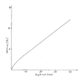
Das Zugkraft/Dehnungsdiagramm eines Kabels nach Figur 2 zeigt bei Raumtemperatur eine relativ geringe Dehnung von 12 o/oo bei einer Zugkraft von 40 KN. Bei der Versuchsdurchführung wurde die Last stetig bis auf 40 KN erhöht, dort ca. 18 min beibehalten und die Last stetig bis auf 0 verringert. Nach Entlastung verblieb eine geringe bleibende Dehnung von ca. 0,5 o/oo.The tensile force / elongation diagram of a cable according to FIG. 2 shows a relatively low elongation of 12 o / oo at a room temperature at 40 KN. When carrying out the test, the load was continuously increased to 40 KN, maintained there for about 18 minutes and the load was continuously reduced to 0. After relief, there was a slight permanent stretch of about 0.5 o / oo.
Versuche bei 60° C zeigten bis 40 KN gegenüber den Werten bei Raumtemperatur ein identisches Zug/Dehnungsverhalten. Durchgeführte Zugversuche bis 70 KN führten selbst nach 7 min Standzeit zu keinem Kabelbruch.Experiments at 60 ° C showed an identical tensile / elongation behavior up to 40 KN compared to the values at room temperature. Tensile tests carried out up to 70 KN did not lead to a cable break even after 7 minutes of inactivity.
Claims (11)
Applications Claiming Priority (2)
| Application Number | Priority Date | Filing Date | Title |
|---|---|---|---|
| DE4015568 | 1990-05-15 | ||
| DE4015568A DE4015568A1 (en) | 1990-05-15 | 1990-05-15 | FO AIR CABLE FOR LARGE CLAMPING LENGTHS |
Publications (3)
| Publication Number | Publication Date |
|---|---|
| EP0456899A2 true EP0456899A2 (en) | 1991-11-21 |
| EP0456899A3 EP0456899A3 (en) | 1993-05-26 |
| EP0456899B1 EP0456899B1 (en) | 1996-10-09 |
Family
ID=6406443
Family Applications (1)
| Application Number | Title | Priority Date | Filing Date |
|---|---|---|---|
| EP90123833A Expired - Lifetime EP0456899B1 (en) | 1990-05-15 | 1990-12-11 | Fibre optic overhead cable for long suspension lengths |
Country Status (8)
| Country | Link |
|---|---|
| EP (1) | EP0456899B1 (en) |
| JP (1) | JP2865898B2 (en) |
| AT (1) | ATE144052T1 (en) |
| DE (2) | DE4015568A1 (en) |
| DK (1) | DK0456899T3 (en) |
| ES (1) | ES2095232T3 (en) |
| FI (1) | FI912340A (en) |
| GR (1) | GR3021584T3 (en) |
Cited By (1)
| Publication number | Priority date | Publication date | Assignee | Title |
|---|---|---|---|---|
| CN111292883A (en) * | 2020-02-17 | 2020-06-16 | 中天科技海缆有限公司 | Light-duty nonmetal armor submarine cable |
Families Citing this family (4)
| Publication number | Priority date | Publication date | Assignee | Title |
|---|---|---|---|---|
| DE10129558A1 (en) * | 2001-04-21 | 2002-10-24 | Nexans France Sa | Optical strand with one or more optical fibers is provided with a plastic cover which carries a reinforcement consisting of at least one helically wound wire or high-strength plastic thread useful or data transmission lines |
| DE202015002585U1 (en) | 2015-04-07 | 2015-07-23 | Brugg Kabel Ag | Cable for connection of above-ground connection points |
| EP3226255A1 (en) | 2016-04-01 | 2017-10-04 | Brugg Kabel AG | Cable for connecting connection points above ground |
| CN112987214B (en) * | 2021-04-13 | 2023-04-07 | 浙江东通光网物联科技有限公司 | Low manufacturing cost optical cable |
Citations (4)
| Publication number | Priority date | Publication date | Assignee | Title |
|---|---|---|---|---|
| EP0221243A2 (en) * | 1985-10-31 | 1987-05-13 | KABEL RHEYDT Aktiengesellschaft | Light wave guide aerial cable |
| EP0228132A2 (en) * | 1985-12-21 | 1987-07-08 | Philips Patentverwaltung GmbH | Method of manufacture of an optical cable |
| EP0261675A2 (en) * | 1986-09-26 | 1988-03-30 | Kabelmetal Electro GmbH | Optical cable |
| WO1990006530A1 (en) * | 1988-12-05 | 1990-06-14 | Kupferdraht-Isolierwerk Ag Wildegg | Self-supporting optical cable |
-
1990
- 1990-05-15 DE DE4015568A patent/DE4015568A1/en not_active Withdrawn
- 1990-12-11 DE DE59010534T patent/DE59010534D1/en not_active Expired - Fee Related
- 1990-12-11 DK DK90123833.7T patent/DK0456899T3/da active
- 1990-12-11 EP EP90123833A patent/EP0456899B1/en not_active Expired - Lifetime
- 1990-12-11 ES ES90123833T patent/ES2095232T3/en not_active Expired - Lifetime
- 1990-12-11 AT AT90123833T patent/ATE144052T1/en not_active IP Right Cessation
-
1991
- 1991-05-14 FI FI912340A patent/FI912340A/en unknown
- 1991-05-14 JP JP3109291A patent/JP2865898B2/en not_active Expired - Lifetime
-
1996
- 1996-11-07 GR GR960402958T patent/GR3021584T3/en unknown
Patent Citations (4)
| Publication number | Priority date | Publication date | Assignee | Title |
|---|---|---|---|---|
| EP0221243A2 (en) * | 1985-10-31 | 1987-05-13 | KABEL RHEYDT Aktiengesellschaft | Light wave guide aerial cable |
| EP0228132A2 (en) * | 1985-12-21 | 1987-07-08 | Philips Patentverwaltung GmbH | Method of manufacture of an optical cable |
| EP0261675A2 (en) * | 1986-09-26 | 1988-03-30 | Kabelmetal Electro GmbH | Optical cable |
| WO1990006530A1 (en) * | 1988-12-05 | 1990-06-14 | Kupferdraht-Isolierwerk Ag Wildegg | Self-supporting optical cable |
Cited By (1)
| Publication number | Priority date | Publication date | Assignee | Title |
|---|---|---|---|---|
| CN111292883A (en) * | 2020-02-17 | 2020-06-16 | 中天科技海缆有限公司 | Light-duty nonmetal armor submarine cable |
Also Published As
| Publication number | Publication date |
|---|---|
| ES2095232T3 (en) | 1997-02-16 |
| EP0456899A3 (en) | 1993-05-26 |
| DK0456899T3 (en) | 1997-03-17 |
| GR3021584T3 (en) | 1997-02-28 |
| ATE144052T1 (en) | 1996-10-15 |
| JP2865898B2 (en) | 1999-03-08 |
| FI912340A0 (en) | 1991-05-14 |
| DE4015568A1 (en) | 1991-11-21 |
| EP0456899B1 (en) | 1996-10-09 |
| JPH04229507A (en) | 1992-08-19 |
| FI912340A (en) | 1991-11-16 |
| DE59010534D1 (en) | 1996-11-14 |
Similar Documents
| Publication | Publication Date | Title |
|---|---|---|
| EP0126509B1 (en) | Optical cable element or cable, and method of making it | |
| EP0054784B1 (en) | Overhead cable with tension members | |
| DE69837579T2 (en) | Fiber optic cable combination | |
| EP0874262A2 (en) | Optical cable and method of manufacturing an optical cable | |
| DE2355855A1 (en) | OPTICAL CABLE | |
| EP0268286A2 (en) | Tensile strength cable | |
| DE2724155A1 (en) | MESSAGE CABLES WITH FIBER OPTIC FIBER WAVE GUIDES | |
| DE3108381A1 (en) | OPTICAL CABLE | |
| DE3118172A1 (en) | Longitudinally watertight optical communication cable | |
| EP0072594B1 (en) | Optical telecommunication cable | |
| EP0042996B1 (en) | Integral optical communication cable | |
| EP0840331A1 (en) | Flexible line | |
| EP0456899B1 (en) | Fibre optic overhead cable for long suspension lengths | |
| DE3127901A1 (en) | Optical telecommunication cable having an optical fibre and a tension-proof secondary coating | |
| DE2512830B2 (en) | Optical fiber television camera cable | |
| DE3446766A1 (en) | Line wire for high-voltage overhead lines | |
| EP0211107B1 (en) | Non-metallic waveguide cable with a cable core | |
| DE3606589C2 (en) | ||
| EP0477416B1 (en) | Optical cable | |
| EP1037082A1 (en) | Dielectrical optical cable | |
| EP0677759A1 (en) | Optical cable with stain and compression resistant bundels | |
| DE3515662C2 (en) | Optical cable | |
| EP0425915B1 (en) | Optical cable | |
| DE3319370A1 (en) | Optical aerial cable having a tubular support element | |
| DE4337997A1 (en) | Metal-free self-supporting optical-fibre overhead cable (aerial cable) |
Legal Events
| Date | Code | Title | Description |
|---|---|---|---|
| PUAI | Public reference made under article 153(3) epc to a published international application that has entered the european phase |
Free format text: ORIGINAL CODE: 0009012 |
|
| AK | Designated contracting states |
Kind code of ref document: A2 Designated state(s): AT BE CH DE DK ES FR GB GR IT LI NL SE |
|
| PUAL | Search report despatched |
Free format text: ORIGINAL CODE: 0009013 |
|
| AK | Designated contracting states |
Kind code of ref document: A3 Designated state(s): AT BE CH DE DK ES FR GB GR IT LI NL SE |
|
| 17P | Request for examination filed |
Effective date: 19930422 |
|
| 17Q | First examination report despatched |
Effective date: 19950908 |
|
| GRAG | Despatch of communication of intention to grant |
Free format text: ORIGINAL CODE: EPIDOS AGRA |
|
| GRAH | Despatch of communication of intention to grant a patent |
Free format text: ORIGINAL CODE: EPIDOS IGRA |
|
| GRAH | Despatch of communication of intention to grant a patent |
Free format text: ORIGINAL CODE: EPIDOS IGRA |
|
| GRAA | (expected) grant |
Free format text: ORIGINAL CODE: 0009210 |
|
| AK | Designated contracting states |
Kind code of ref document: B1 Designated state(s): AT BE CH DE DK ES FR GB GR IT LI NL SE |
|
| REF | Corresponds to: |
Ref document number: 144052 Country of ref document: AT Date of ref document: 19961015 Kind code of ref document: T |
|
| REG | Reference to a national code |
Ref country code: CH Ref legal event code: NV Representative=s name: PATENTANWAELTE GEORG ROEMPLER UND ALDO ROEMPLER |
|
| ITF | It: translation for a ep patent filed |
Owner name: BARZANO' E ZANARDO ROMA S.P.A. |
|
| REF | Corresponds to: |
Ref document number: 59010534 Country of ref document: DE Date of ref document: 19961114 |
|
| GBT | Gb: translation of ep patent filed (gb section 77(6)(a)/1977) |
Effective date: 19961030 |
|
| REG | Reference to a national code |
Ref country code: GR Ref legal event code: FG4A Free format text: 3021584 |
|
| ET | Fr: translation filed | ||
| REG | Reference to a national code |
Ref country code: ES Ref legal event code: FG2A Ref document number: 2095232 Country of ref document: ES Kind code of ref document: T3 |
|
| REG | Reference to a national code |
Ref country code: DK Ref legal event code: T3 |
|
| PLBE | No opposition filed within time limit |
Free format text: ORIGINAL CODE: 0009261 |
|
| STAA | Information on the status of an ep patent application or granted ep patent |
Free format text: STATUS: NO OPPOSITION FILED WITHIN TIME LIMIT |
|
| 26N | No opposition filed | ||
| PGFP | Annual fee paid to national office [announced via postgrant information from national office to epo] |
Ref country code: GB Payment date: 20001115 Year of fee payment: 11 |
|
| PGFP | Annual fee paid to national office [announced via postgrant information from national office to epo] |
Ref country code: CH Payment date: 20001120 Year of fee payment: 11 |
|
| PGFP | Annual fee paid to national office [announced via postgrant information from national office to epo] |
Ref country code: NL Payment date: 20001121 Year of fee payment: 11 |
|
| PGFP | Annual fee paid to national office [announced via postgrant information from national office to epo] |
Ref country code: AT Payment date: 20001122 Year of fee payment: 11 |
|
| PGFP | Annual fee paid to national office [announced via postgrant information from national office to epo] |
Ref country code: GR Payment date: 20001129 Year of fee payment: 11 |
|
| PGFP | Annual fee paid to national office [announced via postgrant information from national office to epo] |
Ref country code: BE Payment date: 20001130 Year of fee payment: 11 |
|
| PGFP | Annual fee paid to national office [announced via postgrant information from national office to epo] |
Ref country code: DK Payment date: 20001201 Year of fee payment: 11 |
|
| PGFP | Annual fee paid to national office [announced via postgrant information from national office to epo] |
Ref country code: SE Payment date: 20001204 Year of fee payment: 11 Ref country code: FR Payment date: 20001204 Year of fee payment: 11 |
|
| PGFP | Annual fee paid to national office [announced via postgrant information from national office to epo] |
Ref country code: DE Payment date: 20001213 Year of fee payment: 11 |
|
| PGFP | Annual fee paid to national office [announced via postgrant information from national office to epo] |
Ref country code: ES Payment date: 20001218 Year of fee payment: 11 |
|
| PG25 | Lapsed in a contracting state [announced via postgrant information from national office to epo] |
Ref country code: GB Free format text: LAPSE BECAUSE OF NON-PAYMENT OF DUE FEES Effective date: 20011211 Ref country code: DK Free format text: LAPSE BECAUSE OF NON-PAYMENT OF DUE FEES Effective date: 20011211 Ref country code: AT Free format text: LAPSE BECAUSE OF NON-PAYMENT OF DUE FEES Effective date: 20011211 |
|
| PG25 | Lapsed in a contracting state [announced via postgrant information from national office to epo] |
Ref country code: SE Free format text: LAPSE BECAUSE OF NON-PAYMENT OF DUE FEES Effective date: 20011212 |
|
| PG25 | Lapsed in a contracting state [announced via postgrant information from national office to epo] |
Ref country code: LI Free format text: LAPSE BECAUSE OF NON-PAYMENT OF DUE FEES Effective date: 20011231 Ref country code: GR Free format text: LAPSE BECAUSE OF NON-PAYMENT OF DUE FEES Effective date: 20011231 Ref country code: CH Free format text: LAPSE BECAUSE OF NON-PAYMENT OF DUE FEES Effective date: 20011231 Ref country code: BE Free format text: LAPSE BECAUSE OF NON-PAYMENT OF DUE FEES Effective date: 20011231 |
|
| REG | Reference to a national code |
Ref country code: GB Ref legal event code: IF02 |
|
| BERE | Be: lapsed |
Owner name: KABELMETAL ELECTRO G.M.B.H. Effective date: 20011231 |
|
| PG25 | Lapsed in a contracting state [announced via postgrant information from national office to epo] |
Ref country code: NL Free format text: LAPSE BECAUSE OF NON-PAYMENT OF DUE FEES Effective date: 20020701 |
|
| PG25 | Lapsed in a contracting state [announced via postgrant information from national office to epo] |
Ref country code: DE Free format text: LAPSE BECAUSE OF NON-PAYMENT OF DUE FEES Effective date: 20020702 |
|
| EUG | Se: european patent has lapsed |
Ref document number: 90123833.7 |
|
| GBPC | Gb: european patent ceased through non-payment of renewal fee |
Effective date: 20011211 |
|
| REG | Reference to a national code |
Ref country code: CH Ref legal event code: PL |
|
| PG25 | Lapsed in a contracting state [announced via postgrant information from national office to epo] |
Ref country code: FR Free format text: LAPSE BECAUSE OF NON-PAYMENT OF DUE FEES Effective date: 20020830 |
|
| NLV4 | Nl: lapsed or anulled due to non-payment of the annual fee |
Effective date: 20020701 |
|
| REG | Reference to a national code |
Ref country code: DK Ref legal event code: EBP |
|
| REG | Reference to a national code |
Ref country code: FR Ref legal event code: ST |
|
| PG25 | Lapsed in a contracting state [announced via postgrant information from national office to epo] |
Ref country code: ES Free format text: LAPSE BECAUSE OF NON-PAYMENT OF DUE FEES Effective date: 20021212 |
|
| REG | Reference to a national code |
Ref country code: ES Ref legal event code: FD2A Effective date: 20030113 |
|
| PG25 | Lapsed in a contracting state [announced via postgrant information from national office to epo] |
Ref country code: IT Free format text: LAPSE BECAUSE OF NON-PAYMENT OF DUE FEES;WARNING: LAPSES OF ITALIAN PATENTS WITH EFFECTIVE DATE BEFORE 2007 MAY HAVE OCCURRED AT ANY TIME BEFORE 2007. THE CORRECT EFFECTIVE DATE MAY BE DIFFERENT FROM THE ONE RECORDED. Effective date: 20051211 |