EP0456868A1 - Error compensation device for an induction type electricity meter - Google Patents
Error compensation device for an induction type electricity meter Download PDFInfo
- Publication number
- EP0456868A1 EP0456868A1 EP90109385A EP90109385A EP0456868A1 EP 0456868 A1 EP0456868 A1 EP 0456868A1 EP 90109385 A EP90109385 A EP 90109385A EP 90109385 A EP90109385 A EP 90109385A EP 0456868 A1 EP0456868 A1 EP 0456868A1
- Authority
- EP
- European Patent Office
- Prior art keywords
- current
- compensation
- dependent
- electricity meter
- error
- Prior art date
- Legal status (The legal status is an assumption and is not a legal conclusion. Google has not performed a legal analysis and makes no representation as to the accuracy of the status listed.)
- Withdrawn
Links
Images


Classifications
-
- G—PHYSICS
- G01—MEASURING; TESTING
- G01R—MEASURING ELECTRIC VARIABLES; MEASURING MAGNETIC VARIABLES
- G01R11/00—Electromechanical arrangements for measuring time integral of electric power or current, e.g. of consumption
- G01R11/02—Constructional details
- G01R11/17—Compensating for errors; Adjusting or regulating means therefor
- G01R11/23—Compensating for errors caused by friction, e.g. adjustment in the light load range
-
- G—PHYSICS
- G01—MEASURING; TESTING
- G01R—MEASURING ELECTRIC VARIABLES; MEASURING MAGNETIC VARIABLES
- G01R11/00—Electromechanical arrangements for measuring time integral of electric power or current, e.g. of consumption
- G01R11/02—Constructional details
- G01R11/17—Compensating for errors; Adjusting or regulating means therefor
- G01R11/21—Compensating for errors caused by damping effects of the current, e.g. adjustment in the overload range
-
- G—PHYSICS
- G01—MEASURING; TESTING
- G01R—MEASURING ELECTRIC VARIABLES; MEASURING MAGNETIC VARIABLES
- G01R21/00—Arrangements for measuring electric power or power factor
- G01R21/133—Arrangements for measuring electric power or power factor by using digital technique
-
- G—PHYSICS
- G01—MEASURING; TESTING
- G01R—MEASURING ELECTRIC VARIABLES; MEASURING MAGNETIC VARIABLES
- G01R35/00—Testing or calibrating of apparatus covered by the other groups of this subclass
- G01R35/04—Testing or calibrating of apparatus covered by the other groups of this subclass of instruments for measuring time integral of power or current
Definitions
- the invention relates to an error compensation arrangement for an electricity meter according to the induction principle according to the preamble of claim 1.
- Electricity meters of this type are described, for example, in the textbook “Fundamentals of Meter Technology", Julius Springer-Verlag, Berlin, 1930, pages 136 to 197. These meters have a so-called voltage iron with a voltage coil to which the mains voltage is applied, and a so-called current iron with a current coil through which the load current flows. Both coils are arranged on an iron core with an air gap and act on a rotatable, magnetically braked rotor disc, which dips into the air gaps of the voltage and current iron and whose magnetic fluxes exert a torque on the disc so that it has a removal capacity dependent speed rotates about its axis of rotation. The speed is determined by a counter and immediately shows the electrical work corresponding to the extraction capacity in kWh.
- each electricity meter of the type described above has a characteristic error, the size of which is determined by the bearing friction of the rotor disk at low load current and by the size of the so-called current damping with increasing load current.
- the invention has for its object the load current-dependent occurring in an electricity meter of the type mentioned Compensate for errors as completely as possible.
- the meter-specific error curve is represented in the form of load current-dependent error values and is transformed with the aid of a control unit into load current-dependent control variables which compensate for the torque exerted on the rotor disk in an error-dependent manner via a compensation circuit.
- the error curve correction according to claim 2 can be simplified in such a way that the auxiliary windings are connected via a multiphase rectifier system to a direct current circuit which serves as a compensation circuit.
- the compensation with digital means is effected by a microcomputer as a control device, in whose memory the error curve of the counter in question is stored in digital form.
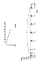
- the typical error curve 1 of an electricity meter according to the induction principle (Ferraris meter) shown in FIG. 1 shows the percentage error F as a function of the percentage load current I of the nominal current I N. From this it can be seen that the percentage error only reaches zero in three points. In the area of load currents I ⁇ I N, the error curve is essentially caused by the friction of the rotor disk of the meter and, in the case of larger load currents, by the so-called current damping, which is essentially proportional to the square of the load current. The current damping is noticeable at load currents from approximately 50% of the nominal current upwards and leads to an increase in the percentage error up to a value of the load current of approximately 300% of the nominal current and then decreases continuously.
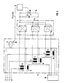
- the position of this error curve in relation to the zero error straight line can be determined by a circuit arrangement shown in FIG. 2 move parallel.
- the voltage irons 2, 3, 4 of a schematically illustrated three-phase electricity meter 5 are provided with auxiliary windings 6, 7, 8.
- Each of these auxiliary windings is connected to a multi-phase rectifier arrangement 9, the output-side DC circuit of which is closed as a compensation circuit via an adjustable electrical load in the form of a load resistor 10 and a smoothing capacitor 11 connected in parallel therewith.
- the size of the burden resistor 10 can be set by a control unit 12 as a function of the load current I drawn from the three-phase network RST by a consumer 16 via the current iron 13, 14, 15 of the electricity meter 5.
- a group of error curves F1, F2, F3, F4 with different electrical burdens or compensation current quantities I K is shown as a parameter.
- the error curve F 1 corresponds to the error curve 1 from FIG. 1. From this it can be seen that the error curves experience a parallel shift when choosing compensation currents I K of different sizes. It follows from this that a corresponding error in the size of the compensation current can be used to determine a zero error point for each individual value of the load current I.
- a prerequisite for such complete error compensation is that the compensation current quantities are correctly assigned to the error curve F.
- an embodiment in digital technology is more expedient.
- a microcomputer is suitable for this purpose, in the memory of which the compensation current values assigned to the relevant load current values are entered and stored in the form of software. This makes it possible to make do with a single hardware configuration, the function of which can be specified individually for each meter using software. The accuracy depends on the density of the compensation values.
- the control of the compensation current I K can then be done in different ways, for example by directly varying the size of the load resistor 10 or, as shown in FIG. 6, with a constant load resistor 19 using an electronic switch 20, the load resistor 19 by starting pulses of different lengths , depending on the size of the control pulse frequency P / s pulse pause duration in the fault circuit.
- a particularly inexpensive embodiment is obtained when an electronic tariff device is assigned to the electricity meter based on the induction principle.
- This usually has a microcomputer that can be used for the prescribed purpose.
Abstract
Description
Die Erfindung betrifft eine Fehlerkompensationsanordnung für einen Elektrizitätszähler nach dem Induktionsprinzip entsprechend dem Oberbegriff des Patentanspruches 1.The invention relates to an error compensation arrangement for an electricity meter according to the induction principle according to the preamble of
Elektrizitätszähler dieser Art sind beispielsweise in dem Lehrbuch "Grundzüge der Zählertechnik", Julius Springer-Verlag, Berlin, 1930, Seiten 136 bis 197, beschrieben. Diese Zähler besitzen ein sogenanntes Spannungseisen mit einer Spannungsspule, an der die Netzspannung anliegt, und ein sogenanntes Stromeisen mit einer Stromspule, die vom Laststrom durchflossen ist. Beide Spulen sind auf je einem Eisenkern mit Luftspalt angeordnet und wirken auf eine drehbare, magnetisch gebremste Läuferscheibe ein, die in die Luftspalte der Spannungs- und Stromeisen eintaucht und deren magnetische Flüsse ein Drehmoment auf die Scheibe ausüben, so daß diese mit einer von der Entnahmeleistung abhängigen Drehzahl um ihre Drehachse rotiert. Die Drehzahl wird von einem Zählwerk ermittelt und zeigt unmittelbar die der Entnahmeleistung entsprechende elektrische Arbeit in kWh an.Electricity meters of this type are described, for example, in the textbook "Fundamentals of Meter Technology", Julius Springer-Verlag, Berlin, 1930, pages 136 to 197. These meters have a so-called voltage iron with a voltage coil to which the mains voltage is applied, and a so-called current iron with a current coil through which the load current flows. Both coils are arranged on an iron core with an air gap and act on a rotatable, magnetically braked rotor disc, which dips into the air gaps of the voltage and current iron and whose magnetic fluxes exert a torque on the disc so that it has a removal capacity dependent speed rotates about its axis of rotation. The speed is determined by a counter and immediately shows the electrical work corresponding to the extraction capacity in kWh.
Nun ist jeder Elektrizitätszähler der vorbeschriebenen Art mit einem charakteristischen Fehler behaftet, dessen Größe bei geringem Laststrom von der Lagerreibung der Läuferscheibe und mit steigendem Laststrom von der Größe der sogenannten Stromdämpfung bestimmt wird. Diese wesentlichen Fehlerquellen haben zur Folge, daß sich ein laststromabhängiger Fehlerverlauf einstellt, der sich mit den bisher bekannten Mitteln zwar minimieren, aber nicht vollständig beseitigen läßt.Now, each electricity meter of the type described above has a characteristic error, the size of which is determined by the bearing friction of the rotor disk at low load current and by the size of the so-called current damping with increasing load current. These essential sources of error have the result that a load-current-dependent error curve is set which can be minimized with the previously known means, but cannot be completely eliminated.
Der Erfindung liegt die Aufgabe zugrunde, den bei einem Elektrizitätszähler der eingangs erwähnten Art auftretenden, laststromabhängigen Fehler möglichst vollständig zu kompensieren.The invention has for its object the load current-dependent occurring in an electricity meter of the type mentioned Compensate for errors as completely as possible.
Diese Aufgabe wird durch die im Patentanspruch 1 angegebene Erfindung dadurch gelöst, daß die zählerspezifische Fehlerkurve in Form von laststromabhängigen Fehlerwerten dargestellt und mit Hilfe eines Steuergerätes in laststromabhängige Steuergrößen transformiert wird, die über einen Kompensationsstromkreis das auf die Läuferscheibe ausgeübte Drehmoment fehlerabhängig kompensieren.This object is achieved by the invention specified in
Bei einem Mehrphasenzähler, beispielsweise einem Drehstromzähler, läßt sich die Fehlerkurvenkorrektur gemäß Patentanspruch 2 in der Weise vereinfachen, daß die Hilfswicklungen über ein Mehrphasen-Gleichrichtersystem auf einen Gleichstromkreis geschaltet sind, der als Kompensationsstromkreis dient.In the case of a multiphase counter, for example a three-phase counter, the error curve correction according to
In einer Weiterbildung nach Patentanspruch 3 wird die Kompensation mit digitalen Mitteln von einem Mikrocomputer als Steuergerät bewirkt, in dessen Speicher die Fehlerkurve des betreffenden Zählers in digitaler Form abgelegt wird. Dadurch besteht die Möglichkeit, ein Steuergerät in einheitlicher Hardware als Chip für alle Arten von Elektrizitätszählern nach dem Induktionsprinzip einzusetzen und die Individualisierung durch Softwareanpassung vorzunehmen.In a further development according to
Bei einem Elektrizitätszähler mit kombinierten elektronischen Tarifgerät ergibt sich eine besonders einfache und kostensparende Möglichkeit gemäß Patentanspruch 5 dadurch, daß der im Tarifgerät bereits vorhandene Mikrocomputer für die Fehlerkorrektur mitbenutzt wird.In the case of an electricity meter with a combined electronic tariff device, there is a particularly simple and cost-saving possibility according to
Weitere vorteilhafte Aus- und Weiterbildungen sind in den übrigen Unteransprüchen gekennzeichnet.Further advantageous training and further education are characterized in the remaining claims.
Anhand von Ausführungsbeispielen wird die Erfindung im folgenden näher erläutert. Darin zeigen:
- Fig. 1
- die typische Fehlerkurve eines Elektrizitätszählers nach dem Induktionsprinzip,
- Fig. 2
- ein Prinzipschaltbild einer Schaltungsanordnung zur Kompensation dieses Fehlers,
- Fig. 3
- in Abhängigkeit von der Höhe des Bürdenwiderstandes des Kompensationsstromkreises parallel verschobene Fehlerkurven,
- Fig. 4
- ein Funktionsdiagramm zur Darstellung der Abhängigkeit der Fehlerkompensation von der Höhe des Kompensationsstromes,
- Fig. 5
- eine Fehlerkurve eines Elektrizitätszählers nach dem Induktionsprinzip ohne und mit Fehlerkompensation, und
- Fig. 6
- das Prinzipschaltbild eines Kompensationsstromkreises mit konstantem Bürdenwiderstand.
- Fig. 1
- the typical error curve of an electricity meter based on the induction principle,
- Fig. 2
- 1 shows a basic circuit diagram of a circuit arrangement for compensating this error,
- Fig. 3
- error curves shifted in parallel depending on the level of the load resistance of the compensation circuit,
- Fig. 4
- 1 shows a functional diagram to show the dependency of the error compensation on the level of the compensation current,
- Fig. 5
- an error curve of an electricity meter based on the induction principle with and without error compensation, and
- Fig. 6
- the basic circuit diagram of a compensation circuit with constant load resistance.
Die in Fig. 1 dargestellte typische Fehlerkurve 1 eines Elektrizitätszählers nach dem Induktionsprinzip (Ferrariszähler) zeigt den prozentualen Fehler F in Abhängigkeit vom prozentualen Laststrom I des Nennstromes IN. Daraus ist zu erkennen, daß der prozentuale Fehler nur in drei Punkten den Nullwert erreicht. Die Fehlerkurve wird im Bereich von Lastströmen I << IN im wesentlichen von der Reibung der Läuferscheibe des Zählers und bei größeren Lastströmen von der sogenannten Stromdämpfung verursacht, die im wesentlichen proportional ist dem Quadrat des Laststromes. Die Stromdämpfung macht sich bei Laststromstärken von etwa 50% des Nennstromes an aufwärts bemerkbar und führt zu einem Anstieg des prozentualen Fehlers bis zu einem Wert des Laststromes von etwa 300% des Nennstromes und fällt dann kontinuierlich ab.The
Die Lage dieser Fehlerkurve in bezug auf die Null-Fehler-Gerade läßt sich durch eine in Fig. 2 dargestellte Schaltungsanordnung parallelverschieben. Dazu werden die Spannungseisen 2, 3, 4 eines schematisch dargestellten Drehstrom-Elektrizitätszählers 5 mit Hilfswicklungen 6, 7, 8 versehen. Jede dieser Hilfswicklungen ist an einer Mehrphasen-Gleichrichteranordnung 9 angeschlossen, deren ausgangsseitiger Gleichstromkreis als Kompensationsstromkreis über eine einstellbare elektrische Bürde in Form eines Bürdenwiderstandes 10 und einen dazu parallelgeschalteten Glättungskondensator 11 geschlossen ist. Die Größe des Bürdenwiderstandes 10 ist von einem Steuergerät 12 in Abhängigkeit von dem über die Stromeisen 13, 14, 15 des Elektrizitätszählers 5 von einem Verbraucher 16 aus dem Drehstromnetz RST entnommenen Laststromes I einstellbar. Die Drehzahl der Läuferscheibe 17 des Elektrizitätszählers 5 ist bei konstanter Netzspannung proportional zum Laststrom I und wird von einer Drehzahlmeßeinrichtung 18, wie sie beispielsweise aus der DE-A-34 36 909 bekannt ist, ermittelt und dem Steuergerät 12 als laststromabhängige Steuerimpulsfrequenz P/s = f(I) zugeführt.The position of this error curve in relation to the zero error straight line can be determined by a circuit arrangement shown in FIG. 2 move parallel. For this purpose, the
In Fig. 3 ist eine Schar von Fehlerkurven F₁, F₂, F₃, F₄ mit unterschiedlichen elektrischen Bürden bzw. Kompensationsstromgrößen IK als Parameter dargestellt. Dabei entspricht die Fehlerkurve F₁ der Fehlerkurve 1 aus Fig. 1. Daraus ist zu erkennen, daß die Fehlerkurven bei der Wahl unterschiedlich großer Kompensationsströme IK eine Parallelverschiebung erfahren. Daraus ergibt sich, daß durch eine entsprechende Wahl der Größe des Kompensationsstromes für jeden einzelnen Wert des Laststromes I ein Null-Fehler-Punkt ermittelt werden kann.In Fig. 3 a group of error curves F₁, F₂, F₃, F₄ with different electrical burdens or compensation current quantities I K is shown as a parameter. The
In Fig. 4 ist anhand der Abhängigkeit des prozentualen Fehlers F vom Kompensationsstrom IK in mA gezeigt, wie hoch der jeweilige Kompensationsstrom sein muß, um bestimmte Fehlergrößen exakt zu kompensieren. Bei richtiger Wahl des Kompensationsstromes ergibt sich die im Diagramm der Fig. 5 dargestellte vollständige Fehlerkompensation, bei der alle angekreuzten, auf der gestrichelt dargestellten Fehlerkurve liegenden Stromwerte des Laststromes I als Punkte auf der Null-Fehler-Geraden liegen.4 shows, based on the dependency of the percentage error F on the compensation current I K in mA, how high the respective compensation current must be in order to exactly compensate for certain error quantities. If the compensation current is selected correctly, the result is the complete error compensation shown in the diagram in FIG. 5, in which all the current values of the load current I which are checked and lie on the dashed curve are shown as points on the zero-error line.
Voraussetzung für eine solche vollständige Fehlerkompensation ist, daß die Kompensationsstromgrößen in richtiger Weise der Fehlerkurve F zugeordnet werden. Dazu bedarf es zunächst der genauen Ermittlung der individuellen Fehlerkurve eines Zählers und der Einspeicherung der dazu passenden Kompensationsstromgrößen in das Steuergerät 12. Dieses kann mit analogen Mitteln geschehen. Zweckmäßiger ist jedoch eine Ausführungsform in Digitaltechnik. Dazu bietet sich ein Mikrocomputer an, in dessen Speicher die den betreffenden Laststromwerten zugeordneten Kompensationsstromwerte in Form von Software eingegeben und abgespeichert werden. Dadurch besteht die Möglichkeit, mit einer einzigen Hardwarekonfiguration auszukommen, deren Funktion per Software zählerindividuell vorgegeben werden kann. Dabei hängt die Genauigkeit von der Dichte der Kompensationswerte ab.A prerequisite for such complete error compensation is that the compensation current quantities are correctly assigned to the error curve F. To do this, it is first necessary to precisely determine the individual error curve of a counter and to store the appropriate compensation current quantities in the
Die Steuerung des Kompensationsstromes IK kann dann auf unterschiedliche Weise beispielweise dadurch geschehen, daß die Größe des Bürdenwiderstandes 10 unmittelbar variiert wird oder, wie in Fig. 6 dargestellt, bei konstantem Bürdenwiderstand 19 mit Hilfe eines elektronischen Schalters 20 der Bürdenwiderstand 19 durch Einschaltimpulse unterschiedlich langer, von der Größe der Steuerimpulsfrequenz P/s abhängiger Impuls-Pausen-Dauer in den Fehlerstromkreis eingeschaltet wird.The control of the compensation current I K can then be done in different ways, for example by directly varying the size of the
Eine besonders kostengünstige Ausführungsform ergibt sich dann, wenn dem Elektrizitätszähler nach dem Induktionsprinzip ein elektronisches Tarifgerät zugeordnet ist. Dieses besitzt üblicherweise einen Mikrocomputer, der für den vorgeschriebenen Zweck mitbenutzt werden kann.A particularly inexpensive embodiment is obtained when an electronic tariff device is assigned to the electricity meter based on the induction principle. This usually has a microcomputer that can be used for the prescribed purpose.
Claims (7)
Priority Applications (2)
| Application Number | Priority Date | Filing Date | Title |
|---|---|---|---|
| EP90109385A EP0456868A1 (en) | 1990-05-17 | 1990-05-17 | Error compensation device for an induction type electricity meter |
| KR1019910007910A KR910020446A (en) | 1990-05-17 | 1991-05-16 | Error Compensator of Power Meter According to Induction Principle |
Applications Claiming Priority (1)
| Application Number | Priority Date | Filing Date | Title |
|---|---|---|---|
| EP90109385A EP0456868A1 (en) | 1990-05-17 | 1990-05-17 | Error compensation device for an induction type electricity meter |
Publications (1)
| Publication Number | Publication Date |
|---|---|
| EP0456868A1 true EP0456868A1 (en) | 1991-11-21 |
Family
ID=8203994
Family Applications (1)
| Application Number | Title | Priority Date | Filing Date |
|---|---|---|---|
| EP90109385A Withdrawn EP0456868A1 (en) | 1990-05-17 | 1990-05-17 | Error compensation device for an induction type electricity meter |
Country Status (2)
| Country | Link |
|---|---|
| EP (1) | EP0456868A1 (en) |
| KR (1) | KR910020446A (en) |
Cited By (3)
| Publication number | Priority date | Publication date | Assignee | Title |
|---|---|---|---|---|
| RU2474834C1 (en) * | 2011-09-09 | 2013-02-10 | Олег Фёдорович Меньших | Circuit to control sensitivity of three-phase electronic devices for power metering |
| CN108152782A (en) * | 2017-12-05 | 2018-06-12 | 国家电网公司 | A kind of test method of massive quantity power supply and measurement electric energy meter more positive coefficient |
| CN110568397A (en) * | 2019-08-12 | 2019-12-13 | 浙江恒业电子有限公司 | Electric energy meter correction method and system based on MCU software |
Citations (4)
| Publication number | Priority date | Publication date | Assignee | Title |
|---|---|---|---|---|
| US2412070A (en) * | 1944-03-18 | 1946-12-03 | Walter C Wagner | Secondary meter for primary energy |
| DE2461259A1 (en) * | 1974-12-23 | 1976-07-01 | Siemens Ag | Electronic counter using photoelectrics - has modulated light emitting diode as light source |
| DE3514371A1 (en) * | 1985-05-28 | 1986-10-23 | Mitsubishi Denki K.K., Tokio/Tokyo | Electronic energy meter for electrical energy |
| WO1990000740A1 (en) * | 1988-07-15 | 1990-01-25 | Sangamo Weston, Inc. | Adjustment circuit and method for solid-state electricity meter |
-
1990
- 1990-05-17 EP EP90109385A patent/EP0456868A1/en not_active Withdrawn
-
1991
- 1991-05-16 KR KR1019910007910A patent/KR910020446A/en not_active Application Discontinuation
Patent Citations (4)
| Publication number | Priority date | Publication date | Assignee | Title |
|---|---|---|---|---|
| US2412070A (en) * | 1944-03-18 | 1946-12-03 | Walter C Wagner | Secondary meter for primary energy |
| DE2461259A1 (en) * | 1974-12-23 | 1976-07-01 | Siemens Ag | Electronic counter using photoelectrics - has modulated light emitting diode as light source |
| DE3514371A1 (en) * | 1985-05-28 | 1986-10-23 | Mitsubishi Denki K.K., Tokio/Tokyo | Electronic energy meter for electrical energy |
| WO1990000740A1 (en) * | 1988-07-15 | 1990-01-25 | Sangamo Weston, Inc. | Adjustment circuit and method for solid-state electricity meter |
Non-Patent Citations (2)
| Title |
|---|
| IEEE TRANSACTIONS ON POWER DELIVERY, Band PWRD-2, Nr. 4, Oktober 1987, Seiten 1018-1024; E. SO: "A current-comparator-based wattmeter for high voltage power measurements at very low power factors" * |
| JOURNAL OF PHYSICS E-SCIENTIFIC INSTRUMENTS, Band 14, Nr. 7, Juli 1981, Seiten 777-782; H.M.J.M. DORTMANS: "Application of microprocessors" * |
Cited By (3)
| Publication number | Priority date | Publication date | Assignee | Title |
|---|---|---|---|---|
| RU2474834C1 (en) * | 2011-09-09 | 2013-02-10 | Олег Фёдорович Меньших | Circuit to control sensitivity of three-phase electronic devices for power metering |
| CN108152782A (en) * | 2017-12-05 | 2018-06-12 | 国家电网公司 | A kind of test method of massive quantity power supply and measurement electric energy meter more positive coefficient |
| CN110568397A (en) * | 2019-08-12 | 2019-12-13 | 浙江恒业电子有限公司 | Electric energy meter correction method and system based on MCU software |
Also Published As
| Publication number | Publication date |
|---|---|
| KR910020446A (en) | 1991-12-20 |
Similar Documents
| Publication | Publication Date | Title |
|---|---|---|
| DE2821225C2 (en) | ||
| DE2658321C2 (en) | Control arrangement for a brushless DC motor | |
| DE3736303C2 (en) | ||
| DE2348667B2 (en) | Electronic kWh counter | |
| DE10337282B4 (en) | Measuring device unit with a magnetic pointer position detector | |
| EP0453518B1 (en) | Current transformer arrangement for three-wire three-phase systems, especially to detect the actual current for controlled dc consumers powered via current rectifiers | |
| DE2635965C3 (en) | Circuit arrangement and method for forming an electrical quantity which is proportional to a flux component in a rotating field machine | |
| EP0456868A1 (en) | Error compensation device for an induction type electricity meter | |
| DE3527801A1 (en) | METHOD AND CIRCUIT FOR MEASURING THE ACTIVE CURRENT AND THE BLIND CURRENT IN AN ELECTRIC AC SYSTEM | |
| DE3625011C2 (en) | ||
| DE3826551C2 (en) | Device for power factor measurement | |
| DE3203257A1 (en) | DEVICE FOR DETERMINING THE COMMON FREQUENCY OF TWO INDEPENDENTLY VARIABLE ALTERNATIVES, ESPECIALLY IN A TURNTABLE MACHINE | |
| EP1460438A1 (en) | Modular electricity meter | |
| DE974154C (en) | Converter for preferably small direct current quantities based on magnetic amplifiers | |
| DE527676C (en) | Device for measuring electrical quantities and their sums at a remote location using alternating current | |
| US2901701A (en) | Power metering system | |
| DE2620992C2 (en) | Device for the machine voltage-synchronized ignition of the inverter valves of a converter motor | |
| DE663256C (en) | Arrangement for regulating and keeping constant counting stations or other measuring devices supplied electrical quantities | |
| DE2260441B2 (en) | ANALOG-DIGITAL CONVERTER | |
| DE701520C (en) | Device for determining the phase position of the negative sequence vector corresponding to an asymmetrical load | |
| DE1638523B2 (en) | PROCEDURE FOR ADJUSTING THE VOLTAGE DELIVERED BY AN AC GENERATOR WITH PERMANENT MAGNETIC RUNNER | |
| DE322500C (en) | ||
| DE146212C (en) | ||
| EP4293894A2 (en) | Method and device for determining an initial rotor position of a three-phase electric motor | |
| DE942754C (en) | Arrangement for speed control of a direct current motor fed by an alternating current source via a rectifier |
Legal Events
| Date | Code | Title | Description |
|---|---|---|---|
| PUAI | Public reference made under article 153(3) epc to a published international application that has entered the european phase |
Free format text: ORIGINAL CODE: 0009012 |
|
| 17P | Request for examination filed |
Effective date: 19901205 |
|
| AK | Designated contracting states |
Kind code of ref document: A1 Designated state(s): AT CH DE DK FR GB IT LI SE |
|
| STAA | Information on the status of an ep patent application or granted ep patent |
Free format text: STATUS: THE APPLICATION IS DEEMED TO BE WITHDRAWN |
|
| 18D | Application deemed to be withdrawn |
Effective date: 19931201 |