EP0456866A1 - Blow mold - Google Patents
Blow mold Download PDFInfo
- Publication number
- EP0456866A1 EP0456866A1 EP90109370A EP90109370A EP0456866A1 EP 0456866 A1 EP0456866 A1 EP 0456866A1 EP 90109370 A EP90109370 A EP 90109370A EP 90109370 A EP90109370 A EP 90109370A EP 0456866 A1 EP0456866 A1 EP 0456866A1
- Authority
- EP
- European Patent Office
- Prior art keywords
- mold
- control
- drive
- mold halves
- pivot shaft
- Prior art date
- Legal status (The legal status is an assumption and is not a legal conclusion. Google has not performed a legal analysis and makes no representation as to the accuracy of the status listed.)
- Granted
Links
Images


Classifications
-
- B—PERFORMING OPERATIONS; TRANSPORTING
- B29—WORKING OF PLASTICS; WORKING OF SUBSTANCES IN A PLASTIC STATE IN GENERAL
- B29C—SHAPING OR JOINING OF PLASTICS; SHAPING OF MATERIAL IN A PLASTIC STATE, NOT OTHERWISE PROVIDED FOR; AFTER-TREATMENT OF THE SHAPED PRODUCTS, e.g. REPAIRING
- B29C33/00—Moulds or cores; Details thereof or accessories therefor
- B29C33/20—Opening, closing or clamping
- B29C33/26—Opening, closing or clamping by pivotal movement
-
- B—PERFORMING OPERATIONS; TRANSPORTING
- B29—WORKING OF PLASTICS; WORKING OF SUBSTANCES IN A PLASTIC STATE IN GENERAL
- B29C—SHAPING OR JOINING OF PLASTICS; SHAPING OF MATERIAL IN A PLASTIC STATE, NOT OTHERWISE PROVIDED FOR; AFTER-TREATMENT OF THE SHAPED PRODUCTS, e.g. REPAIRING
- B29C33/00—Moulds or cores; Details thereof or accessories therefor
- B29C33/20—Opening, closing or clamping
- B29C33/202—Clamping means operating on closed or nearly closed mould parts, the clamping means being independently movable of the opening or closing means
-
- B—PERFORMING OPERATIONS; TRANSPORTING
- B29—WORKING OF PLASTICS; WORKING OF SUBSTANCES IN A PLASTIC STATE IN GENERAL
- B29C—SHAPING OR JOINING OF PLASTICS; SHAPING OF MATERIAL IN A PLASTIC STATE, NOT OTHERWISE PROVIDED FOR; AFTER-TREATMENT OF THE SHAPED PRODUCTS, e.g. REPAIRING
- B29C49/00—Blow-moulding, i.e. blowing a preform or parison to a desired shape within a mould; Apparatus therefor
- B29C49/42—Component parts, details or accessories; Auxiliary operations
- B29C49/56—Opening, closing or clamping means
- B29C2049/566—Locking means
- B29C2049/5661—Mechanical
Definitions
- the present invention relates to a blow mold comprising two mold halves pivotable about a common pivot axis and adapted to form an internal chamber for making a bottle and means for locking the mold halves relative to each other in their closed position.
- Stretch blow molding machines utilizing such a blow mold are disclosed, for example, in West Germany Patent No. 3,336,071 or Japanese Laid-Open Patent Application No. 101137/1989. Since the two mold halves of such a blow mold are opened and closed in a pivotal motion, they can be rapidly closed after a preform has been inserted into the interior of the blow mold and rapidly opened after a blow molded article has been formed. This is very advantageous in that the cycle of blow molding can be shortened.
- the speed of operation in the stretch blow molding machines thus accomplished depends exclusively on the speed of each of the moving steps, that is, a step at which the mold halves are moved toward each other and locked relative to each other to close the blow mold and another step at which the mold halves are unlocked from each other and moved away from each other to open the blow mold.
- This object is accomplished, in accordance with the present invention, by providing a mold drive/control mechanism which receives a driving power transmitted from a single power source to control the pivotal closing and subsequent locking motions of the first and second mold halves and also to control the unlocking and subsequent pivotal opening motions of the first and second mold halves.
- the mold drive/control mechanism can control the pivotal motion of the mold halves and the locking/unlocking motion of the locking member in a predetermined positive timing and yet in a smooth and rapid manner.
- the control process for the interrelated motions of the mold halves in the blow mold can be performed in an optimum sequence without creation of undesirable combination of various motions or interference between the components being moved.
- this mold drive/control mechanism comprises: a control slider reciprocated by means of a drive; a mold motion controlling cam formed on the camming face of said control slider; a lock/unlock controlling cam formed on the camming face of the control slider; a mold drive cam follower driven by the mold motion controlling cam to produce an actuating force for pivotally moving first and second mold halves into their closed and opened positions; and a lock/unlock drive cam follower driven by said lock/unlock controlling cam to produce an actuating force for moving locking member into their locking and unlocking directions, whereby a mechanical engagement can be performed to provide a positive operation.
- the mold drive/control mechanism can be made compact by that the camming face of said control slider on which the mold motion controlling cam is formed is positioned concetrically about a pivot shaft.
- the mold motion control cam consists of first and second cam portions for pivotally moving the first and second mold halves, respectively.
- the first and second cam portions are so arranged that they are positioned to have a minimum spacing therebetween when the first and second mold halves are pivotally moved to their opened position and that there is provided a maximum spacing between the first and second cam portions when the first and second mold halves are brought into contact with each other.
- a lock/unlock drive mechanism for the locking member which comprises a lever adapted to be pivoted following the movement of the lock/unlock drive cam follower, When the pivoted lever engages, at its distal end, with said locking member, the latter can be slidably moved in its locking and unlocking directions, respectively.
- a bottom mold may be provided at one end of the pivot shaft for the first and second mold halves so as to form a portion of the internal chamber in the blow mold.
- the bottom mold is preferably connected with a bottom mold drive/control mechanism adapted to receive a driving power from said power source such that the bottom mold can be vertically moved along said pivot shaft.
- the movability of the bottom mold increases the number of types of hollow articles which can be molded by the blow mold according to the present invention.
- the bottom mold may be used to form a hollow article having a bottom wall which extends inwardly convexly into the internal chamber of the blow mold.
- the bottom mold has a raised portion for forming the inwardly and convexly extending bottom wall in the hollow article.
- the bottom mold drive/control mechanism comprises: a slider block reciprocatable with the control slider; a drive cam formed on the slider block; a control cylinder reversibly rotated by the reciprocation of the slider block and having a cam follower driven by the drive cam; a bottom mold drive/control cam formed on the camming face of the control cylinder; and a bottom mold driving lever having a pivot point at its middle between the opposite ends and having a cam follower formed thereon at one end and driven by the bottom mold drive/control cam with the opposite end being vertically movable with the bottom mold.
- the bottom mold can be automatically centered under the action of the pressure faces engaging with each other when the internal chamber is defined by the first and second mold halves together with the bottom mold.
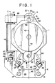
- Figure 1 is a plan view of a blow mold constructed in accordance with one embodiment of the present invention, showing the blow mold in its closed position.
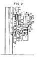
- Figure 2 is a side view of the blow mold in its closed position.
- Figure 3 is a side view of the blow mold in its opened position.
- Figure 4 is a plan view of the blow mold in its opened position.
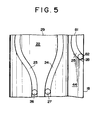
- Figure 5 is an exploded view of the camming face of a control slider as viewed from the direction of arrow I in Figure 1.
- Figure 6 is a cross-sectional view taken along a line II-II in Figure 1.
- Figure 7 is a cross-sectional view taken along a line III-III in Figure 1.
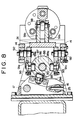
- Figure 8 is a cross-sectional view taken along a line IV-IV in Figure 2.
- Figure 9 is an exploded view of a control cylinder.
- a blow mold constructed in accordance with the present invention, which generally comprises a first mold half 1, a second mold half 2 and a bottom mold 3. As shown in Figure 2, the bottom mold 3 extends into the interior of the blow mold beyond the lower ends 4 of the first and second mold halves 1 and 2.
- the mold halves 1 and 2 are pivotably supported on a common pivot shaft 5 such that the mold halves can be pivoted toward and away from each other.
- locking means 6 for locking the first and second mold halves 1 and 2 relative to each other, the locking means 6 being located at a position diametrically opposite to the pivot shaft 5.
- the first and second mold halves 1 and 2 defines an internal chamber 7 therebetween, which is used to form a hollow article 8 from a preform (not shown) in the stretch blow molding process.
- the internal chamber 7 has a central axis 9 extending in the vertical direction, to which the pivot shaft 5 extends parallel.
- the bottom mold 3 is supported by guide bars 10 and 11 such that the bottom mold 3 can be moved axially along the central axis 9 of the internal chamber 7.
- the guide bars 10 and 11 extend substantially parallel to the central axis 9 and movably supported by a third bracket 12.
- the third bracket 12 is fixedly mounted on a stationary column 13 which also fixedly supports two other brackets 14 and 15 spaced axially away from each other.
- These brackets 12, 14 and 15 longitudinally movably support two parallel tie rods 16 and 17 spaced away from each other and extending parallel to the pivot shaft 5.
- the tie rods 16 and 17 fixedly support a control slider 18 which is in turn connected with a hydraulic piston 20 through a piston rod 19.
- the hydraulic piston 20 is slidably received within a hydraulic cylinder 21 which is fixedly mounted on the first bracket 15.
- the pivot shaft 5 is spanned between and journalled at its opposite ends by the first and second brackets 15 and 14.
- the control slider 18 coaxially surrounds the pivot shaft 5 and movable between the brackets 14 and 15.
- the control slider 18 includes a camming face 22 formed therein at the inner wall facing to the pivot shaft 5.
- the camming face 22 is formed with three control cams (camming grooves) 23, 24 and 25 extending along the length of the control slider 18.
- Each of the control cams 23, 24 or 25 rotatably supports the corresponding one of driven rollers 26, 27 and 28.
- control cams 23 and 24 are spaced apart from each other with the maximum spacing at the end face 29 of the control slider 18 closer to the first bracket 15 while the control cams 23 and 24 are spaced apart from each other with the minimum spacing at the end face 30 of the control slider 18 opposite to the end face 29 thereof.
- Each of the control cams 23 and 24 is formed to be of a gently elongated S-shaped configuration between the end faces 29 and 30 of the control slider 18.
- Each of the driven rollers 26 and 27 is slidably guided within the respective one of the S-shaped control cams 23 and 24 as the control slider 18 moves on and along the tie rods 16 and 17.
- the driven rollers 26 and 27 are laterally moved toward each other as the control slider 18 moves away from the first bracket 15 toward the second bracket 14. As the control slider 18 moves in the opposite direction, the driven rollers 26 and 27 are moved away from each other.
- each of the driven rollers 26 and 27 is rotatably supported by one of shafts 31 and 32 which in turn mounted on driven bodies 35 and 36 through bolt means 33 and 34, respectively.
- Each of the driven bodies 35 and 36 is an L-shaped member as shown by 38 in Figure 2, its shorter leg 39 being connected with the corresponding one of the driven rollers 26 and 27 through the bolt means 33 or 34.
- the longer leg 40 of each of the L-shaped driven bodies 35 and 36 is mounted on the outer wall 41 of the corresponding one of the first and second mold halves 1 and 2.
- the movement of the driven rollers 26 and 27 is transmitted to the first and second mold halves 1 and 2 through the driven bodies 35 and 36, such that the first and second mold halves 1 and 2 are pivotably moved about the pivot shaft 5 depending on the direction of movement of the driven rollers 26 and 27.
- the control cams 23 and 24 are shaped as follows: When the driven rollers 26 and 27 are on the side of the end face 29 of the control slider 18 (in the state shown in Figure 2), the first and second mold halves 1 and 2 are urged against each other at their boundary faces 42 and 43.
- the first and second mold halves 1 and 2 are separated away from each other to completely open the internal chamber 7 as shown in Figure 4.
- the middle portion of each of the control cams 23 and 24 is configured in accordance with the desired motion of the first and second mold halves 1 and 2.
- the first and second mold halves 1 and 2 must be maintained at its close state until a hollow article 8 is completely formed into the desired and final configuration within the internal chamber 7 of the blow mold.
- the first and second mold halves 1 and 2 should be moved apart from each other as fast as possible such that the finished hollow article 8 is removed out of the internal chamber 7 and then a new preform is received in the internal chamber 7.
- the third control cam 25 extends longitudinally along the side face 44 continuing to the camming face 22 of the control slider 18.
- the side face 44 also extends substantially perpendicular to each of the end faces 29 and 30 of the control slider 18.
- a plane including the side face 44 extends substantially perpendicular to a central plane 45 including the opposed boundary faces 42 and 43 of the first and second mold halves 1 and 2.
- the central plane 45 passes through the central axis 9.
- the driven roller 28 guided by the control cam 25 pivotably supports a connecting lever 46 which is in turn fixedly connected to a pivot shaft 47 at one end.
- the pivot shaft 47 extends through the marginal region 48 defined by the first and second mold halves 1 and 2 and supports a swingable lever 49 at the end of the pivot shaft 47 remote from the control slider 18.
- the swingable lever 49 extends toward the locking means 6 in the direction substantially perpendicular to the pivot shaft 47 and includes an outer end 50 remote from the pivot shaft 47, which end 50 is configured into a hook as shown by 51 in Figure 1.
- the hook-shaped end 50 engages a locking rod 52 in the locking mean.
- the second mold half 2 includes a pair of ring members 58 spaced longitudinally away from each other on the side of the second mold half 2 opposite to the pivot shaft 5.
- the first mold half 1 includes a pair of cut-out ring members 57 longitudinally spaced away from each other on the side of the first mold half 1 opposite to the pivot shaft 5, these cut-out ring members 57 acting as locked members.
- Each of the ring members 58 is formed with an aperture 56 of circular cross-section while each of the cut-out ring members 57 includes an aperture 55 of circular cross-section formed with an arcuate cut-out 55a as shown in Figure 4.
- the locking rod 52 has a circular cross-section corresponding to the cross-section in the apertures 55 and 56 and vertically slidably extends through the aperture 56 of the second mold half 2.
- the locking rod 52 includes cylindrical sections 59, 60, 61 and 62 and a connecting member 63 or 64 between each adjacent cylindrical sections 59, 60 or 61, 62, each of the connecting members 63 and 64 having a non-cylindrical section 65 or 66.
- each cut-out ring members 57 has a dimension corresponding to the the non-cylindrical sections 65.
- the locking rod 52 will be received in the cut-out ring members 57 within the range defined by the non-cylindrical sections 65 and 66.
- the cut-outs 55a are formed within a range 77 in which the end of the first mold half 1 remote from the pivot shaft 5 connects to the cut-out ring members 57 (see Figure 7).
- a connecting member 67 which has a connecting portion 68 having its external diameter smaller than those of the cylindrical sections 60 an 61.
- the external diameter of the connecting portion 68 is enough to support a driven roller 69 which is rotatably supported by the end 50 of the swingable lever 49.
- the driven roller 69 is on one hand in contact with an end face 71 bounding the cylindrical section 60 at the roller face 70 of the driven roller 69 and on the other hand in contact with a driven member 72.
- the driven member 72 bounds the connecting member 68 on the side opposite to the end face 71.
- Each of the cut-out ring members 57 is of U-shaped configuration and comprises two legs 78 and 79 and a coupling iron 80 connecting the legs with each other.
- the legs 78 and 79 of each of the cut-out ring members 57 are aligned with the upper and lower end faces of the corresponding ring member 58. Since these legs 78 and 79 are connected with each other through the coupling iron 80, each of the cut-out ring members 57 is increased in strength. Therefore, the cut-out ring members 57 can be prevented from being deformed even if the locking rod 52 is passed through the apertures 56 and 55 in the ring and cut-out ring members 58 and 57.
- the cylindrical sections 59, 60, 61 and 62 of the locking rod 52 extend through the region defined by the apertures 55 formed through the legs 78 and 79.
- the cylindrical sections 59, 60, 61 and 62 extend beyond the region defined by the legs 78 and 79 in the direction toward the apertures 56 of the ring members 58 inserted between the legs 78 and 79 in such an extent that the cylindrical sections 59, 60, 61 and 62 rigidly pass through the apertures 56 and 55.
- the swingable lever 49 is pivoted to move the locking rod 52 toward the bottom mold 3 along the longitudinal axis 73 of the locking rod 52 under the action of the driven roller 69.
- the cylindrical sections 59, 60, 61 and 62 will be located only within the region represented by the apertures 56 of the ring members 58.
- the locking rod 52 can be removed out of the cut-out ring members 57 in the presence of the non-cylindrical sections 65 and 66.
- the connecting members 63 and 64 on which the non-cylindrical sections 65 and 66 are formed are positioned in the region represented by two legs 79 on the respective cut-out ring members 57.
- the locking rod 52 can be separated out of the upper legs 78 while the driven member 72 on the locking rod 52 is positioned within the region defined by the lower legs 78.
- the locking means 6 is actuated into its lock position if the swingable lever 49 is in one of its two pivoted positions and into its unlock position if the swingable lever 49 is in the other pivoted position.
- the pivotal movement of the swingable lever 49 is caused by the movement of the driven roller 28 within the control cam 25 while twisting the pivot shaft 47.
- This movement of the swingable lever 49 is controlled by the S-shaped control cam 25 from the unlock position of the locking means 6 within the range of the end face 29 to the lock position of the same below the end face 29.
- the driven roller 28 is moved from the start position 81 at the end face 29 to the end position 82, as shown in Figure 5.
- the vertical movement of the bottom mold 3 also is controlled by means of the control slider 18.
- an elevator member 84 as slider block is fixedly mounted on the vertical movable tie rods 16 and 17, as shown in Figure 8.
- the driven roller 85 is rotatably mounted on the elevator member 84.
- a shaft 87 is located between the second bracket 14 and the third bracket 12 and rotatably supports a control cylinder 86 which has an outer wall of cylindrical configuration 88 formed with two control cams 89a, 89b and a cam follower 90, all of them being machined into groove configruation, as shown in Figures 8 and 9.
- the cam follower 90 is engaged by the driven roller 85 which is rotatable relative to the elevator member 84.
- the driven roller acts as a drive cam to drive the cam follower 90 which in turn reversibly rotates the control cylinder 86.
- control cam 89a and 89b When the control cylinder 86 is rotated on the shaft 87 by the movement of the elevator member 84, the control cam 89a and 89b cause a two-armed lever 91 to pivot for vertically moving the bottom mold 3.
- the control cams 89a and 89b are so shaped that they are adapted accurately to the desired movement of the bottom mold 3.
- the two-armed lever 91 is fixedly mounted on pivot shafts 92 which are rotatably supported by the second bracket 14.
- the two-armed lever 91 comprises a first pair of arm sections 91a extending adjacent the opposite sides of the control cylinder 88 and a second pair of arm sections 91b extending toward the outer bottom wall of the bottom mold 3.
- the pivot shafts 92 are fixedly mounted on the first pair of arm sections 91a at their proximal ends.
- the distal ends of the first pair of arm sections 91a rotatably support driven rollers 93 which engage in the control cams 89a and 89b on the control cylinder 88, respectively.
- a driven roller 98 is rotatably supported between the second pair of arm sections 91b at their distal ends.
- the driven roller 98 is located between two blocks 95 and 96 which are fixedly mounted on the guide bars 10 and 11 vertically movable together with the bottom mold 3 and spaced vertically apart from each other. Between the two blocks 95 and 96, there is provided a member (not shown) contacting the driven roller 98 at its upper and lower sides. Thus, the driven roller 98 will move the bottom mold 3 toward or away from the first and second mold halves 1 and 2, depending on the pivotal movement of the two-armed lever 91. The bottom mold 3 can be moved at very increased speed since the movement of the bottom mold 3 is performed relating to the configuration of the control cams 89a and 89b.
- the bottom opening 99 includes a pressure sloped face 100 formed on the bottom mold 3 as shown in Figure 1 and pressure faces 101 formed on the mold halves 1 and 2 with the same angle as that of the pressure face 100.
- Each of the first and second mold halves 1, 2 has a support frame 102 or 103 for connecting each of the cut-out ring members 57 with the corresponding one of the ring members 58.
- Each of the support frames 102 or 103 includes a build-in element 104 or 105 mounted therein.
- the built-in elements 104 and 105 defines an internal chamber 7 of desired hollow configuration. Depending on the configuration of an hollow article 8 to be blow molded, various shapes of built-in elements 104 and 105 will be selected and mounted on the support frames 102 and 103.
- the bottom mold 3 also includes a mold member 106 mounted thereon and having its configuration selected depending on that of the bottom mold 3.
- the mold member 106 may be formed with a raised portion 107 inwardly convexly extending into the internal chamber 7. This enables a hollow container 8 having a concave bottom wall internally extending thereinto to be blow molded. This procedure is advantageous in that a stable bottle with hollow legs can be blow molded in accordance with the principle of the present invention.
- control slider 18 is first moved toward the first bracket 15 under the action of the piston rod 19.
- the first and second mold halves 1 and 2 are then moved apart from each other to open the internal chamber 7 defined therebetween. In this position, a preform (not shown) is inserted into the internal chamber 7.
- the hydraulic cylinder 21 is reversely energized to cause the piston rod 19 to move the control slider 18 toward the second bracket 14.
- the driven rollers 26 and 27 are slidably moved within and along the respective control cams 23 and 24 to separate the driven rollers 26 and 27 apart from each other. This movement of the driven rollers 26 and 27 is performed as a pivotal motion about the pivot shaft 5. Due to this pivotal motion, the first and second mold halves 1 and 2 are pivotally brought into contact with each other.
- the locking rod 52 supported by the ring members 56 on the second mold half 2 is received in the cut-out ring members 55 on the first mold half 1 through the cut-outs 55a thereof.
- the elevator member 84 is downwardly moved together with the tie rods 16 and 17 to engage the driven roller 85 as a drive cam with the cam follower 90.
- the engagement of the driven roller 85 with the cam follower 90 causes the control cylinder 86 to rotate about the shaft 87 thereof.
- the driven rollers 93 supported by the first pair of arm sections 91a in the two-armed lever 91 are moved within the respective control cams 89a and 89b to pivot the two-armed lever 91.
- the driven roller 98 supported by the distal ends of the second pair of arm sections 91b will cause the bottom mold 3 to move toward the first and second mold halves 1 and 2 until the bottom mold is fitted into the bottom opening 99. Since such a motion is performed together with the pivotal movement of the first and second mold halves 1 and 2, the internal chamber 7 will be completely defined by the first and second mold halves 1, 2 and the bottom mold 3 on termination of the linear movement of the control slider 18.
- control slider 18 is returned back to the first bracket 15 through the action of the piston rod 19. All the aforementioned cycle is reversely proceeded under the control of the camming members. In such a manner, any interference will not be created between the movable elements during movement. Further, the movement of the movable elements can be harmonized with one another such that the internal chamber 7 can be more rapidly closed and opened.
Abstract
Description
- The present invention relates to a blow mold comprising two mold halves pivotable about a common pivot axis and adapted to form an internal chamber for making a bottle and means for locking the mold halves relative to each other in their closed position.
- Stretch blow molding machines utilizing such a blow mold are disclosed, for example, in West Germany Patent No. 3,336,071 or Japanese Laid-Open Patent Application No. 101137/1989. Since the two mold halves of such a blow mold are opened and closed in a pivotal motion, they can be rapidly closed after a preform has been inserted into the interior of the blow mold and rapidly opened after a blow molded article has been formed. This is very advantageous in that the cycle of blow molding can be shortened. The speed of operation in the stretch blow molding machines thus accomplished depends exclusively on the speed of each of the moving steps, that is, a step at which the mold halves are moved toward each other and locked relative to each other to close the blow mold and another step at which the mold halves are unlocked from each other and moved away from each other to open the blow mold.
- In the conventional stretch blow molding machines disclosed in the aforementioned known literatures, the pivotal motion and locking/unlocking motion of the two mold halves were performed by the transmission of driving forces thereto from separate power sources. In such a case, these different motions were difficult to be harmonized with each other. It was particularly difficult to provide a harmonization between the movement of the mold halves into their closed position and the subsequential locking action on the mold halves and between the unlocking action on the mold halves and the subsequential movement of the mold halves into their open position.
- It is therefore an object of the present invention to provide a blow mold of the above type which can be closed and opened more smoothly and rapidly by providing a harmonization between the pivotal and locking motions required to close the mold halves and between the unlocking and pivotal motions required to open the mold halves.
- This object is accomplished, in accordance with the present invention, by providing a mold drive/control mechanism which receives a driving power transmitted from a single power source to control the pivotal closing and subsequent locking motions of the first and second mold halves and also to control the unlocking and subsequent pivotal opening motions of the first and second mold halves.
- Since actuated by the driving force from the single power source, the mold drive/control mechanism can control the pivotal motion of the mold halves and the locking/unlocking motion of the locking member in a predetermined positive timing and yet in a smooth and rapid manner. Thus, the control process for the interrelated motions of the mold halves in the blow mold can be performed in an optimum sequence without creation of undesirable combination of various motions or interference between the components being moved.
- For such a purpose, this mold drive/control mechanism comprises:
a control slider reciprocated by means of a drive;
a mold motion controlling cam formed on the camming face of said control slider;
a lock/unlock controlling cam formed on the camming face of the control slider;
a mold drive cam follower driven by the mold motion controlling cam to produce an actuating force for pivotally moving first and second mold halves into their closed and opened positions; and
a lock/unlock drive cam follower driven by said lock/unlock controlling cam to produce an actuating force for moving locking member into their locking and unlocking directions, whereby a mechanical engagement can be performed to provide a positive operation. - The mold drive/control mechanism can be made compact by that the camming face of said control slider on which the mold motion controlling cam is formed is positioned concetrically about a pivot shaft. In such a case, the mold motion control cam consists of first and second cam portions for pivotally moving the first and second mold halves, respectively. The first and second cam portions are so arranged that they are positioned to have a minimum spacing therebetween when the first and second mold halves are pivotally moved to their opened position and that there is provided a maximum spacing between the first and second cam portions when the first and second mold halves are brought into contact with each other.
- There is also provided a lock/unlock drive mechanism for the locking member, which comprises a lever adapted to be pivoted following the movement of the lock/unlock drive cam follower, When the pivoted lever engages, at its distal end, with said locking member, the latter can be slidably moved in its locking and unlocking directions, respectively.
- In order to form a bottom wall in a hollow article formed by the blow mold, a bottom mold may be provided at one end of the pivot shaft for the first and second mold halves so as to form a portion of the internal chamber in the blow mold.
- The bottom mold is preferably connected with a bottom mold drive/control mechanism adapted to receive a driving power from said power source such that the bottom mold can be vertically moved along said pivot shaft. The movability of the bottom mold increases the number of types of hollow articles which can be molded by the blow mold according to the present invention. For example, the bottom mold may be used to form a hollow article having a bottom wall which extends inwardly convexly into the internal chamber of the blow mold. In such a case, the bottom mold has a raised portion for forming the inwardly and convexly extending bottom wall in the hollow article.
- The bottom mold drive/control mechanism comprises:
a slider block reciprocatable with the control slider;
a drive cam formed on the slider block;
a control cylinder reversibly rotated by the reciprocation of the slider block and having a cam follower driven by the drive cam;
a bottom mold drive/control cam formed on the camming face of the control cylinder; and
a bottom mold driving lever having a pivot point at its middle between the opposite ends and having a cam follower formed thereon at one end and driven by the bottom mold drive/control cam with the opposite end being vertically movable with the bottom mold. - If pressure faces sloped with the same angle are formed respectively on the bottom mold and the first and second mold halves, the bottom mold can be automatically centered under the action of the pressure faces engaging with each other when the internal chamber is defined by the first and second mold halves together with the bottom mold.
- Figure 1 is a plan view of a blow mold constructed in accordance with one embodiment of the present invention, showing the blow mold in its closed position.
- Figure 2 is a side view of the blow mold in its closed position.
- Figure 3 is a side view of the blow mold in its opened position.
- Figure 4 is a plan view of the blow mold in its opened position.
- Figure 5 is an exploded view of the camming face of a control slider as viewed from the direction of arrow I in Figure 1.
- Figure 6 is a cross-sectional view taken along a line II-II in Figure 1.
- Figure 7 is a cross-sectional view taken along a line III-III in Figure 1.
- Figure 8 is a cross-sectional view taken along a line IV-IV in Figure 2.
- Figure 9 is an exploded view of a control cylinder.
- The present invention will now be described in details with reference to an embodiment thereof illustrated in the drawings.
- Referring now to Figures 1 and 2, there is shown a blow mold constructed in accordance with the present invention, which generally comprises a first mold half 1, a
second mold half 2 and abottom mold 3. As shown in Figure 2, thebottom mold 3 extends into the interior of the blow mold beyond thelower ends 4 of the first andsecond mold halves 1 and 2. Themold halves 1 and 2 are pivotably supported on acommon pivot shaft 5 such that the mold halves can be pivoted toward and away from each other. - There is provided locking means 6 for locking the first and
second mold halves 1 and 2 relative to each other, the locking means 6 being located at a position diametrically opposite to thepivot shaft 5. In their locked position, the first andsecond mold halves 1 and 2 defines aninternal chamber 7 therebetween, which is used to form ahollow article 8 from a preform (not shown) in the stretch blow molding process. Theinternal chamber 7 has acentral axis 9 extending in the vertical direction, to which thepivot shaft 5 extends parallel. - The
bottom mold 3 is supported byguide bars 10 and 11 such that thebottom mold 3 can be moved axially along thecentral axis 9 of theinternal chamber 7. Theguide bars 10 and 11 extend substantially parallel to thecentral axis 9 and movably supported by athird bracket 12. Thethird bracket 12 is fixedly mounted on astationary column 13 which also fixedly supports twoother brackets brackets parallel tie rods pivot shaft 5. Thetie rods control slider 18 which is in turn connected with ahydraulic piston 20 through apiston rod 19. Thehydraulic piston 20 is slidably received within ahydraulic cylinder 21 which is fixedly mounted on thefirst bracket 15. - The
pivot shaft 5 is spanned between and journalled at its opposite ends by the first andsecond brackets control slider 18 coaxially surrounds thepivot shaft 5 and movable between thebrackets control slider 18 includes acamming face 22 formed therein at the inner wall facing to thepivot shaft 5. Thecamming face 22 is formed with three control cams (camming grooves) 23, 24 and 25 extending along the length of thecontrol slider 18. Each of thecontrol cams rollers control cams end face 29 of thecontrol slider 18 closer to thefirst bracket 15 while thecontrol cams end face 30 of thecontrol slider 18 opposite to theend face 29 thereof. Each of thecontrol cams control slider 18. Each of the drivenrollers control cams control slider 18 moves on and along thetie rods control slider 18, the drivenrollers control slider 18 moves away from thefirst bracket 15 toward thesecond bracket 14. As thecontrol slider 18 moves in the opposite direction, the drivenrollers - As shown in Figure 1, each of the driven
rollers shafts bodies bodies shorter leg 39 being connected with the corresponding one of the drivenrollers longer leg 40 of each of the L-shaped drivenbodies second mold halves 1 and 2. In such an arrangement, the movement of the drivenrollers second mold halves 1 and 2 through the drivenbodies second mold halves 1 and 2 are pivotably moved about thepivot shaft 5 depending on the direction of movement of the drivenrollers control cams
When the drivenrollers end face 29 of the control slider 18 (in the state shown in Figure 2), the first andsecond mold halves 1 and 2 are urged against each other at their boundary faces 42 and 43. On the contrary, when the drivenrollers second mold halves 1 and 2 are separated away from each other to completely open theinternal chamber 7 as shown in Figure 4. The middle portion of each of thecontrol cams second mold halves 1 and 2. In this connection, the first andsecond mold halves 1 and 2 must be maintained at its close state until ahollow article 8 is completely formed into the desired and final configuration within theinternal chamber 7 of the blow mold. On the other hand, the first andsecond mold halves 1 and 2 should be moved apart from each other as fast as possible such that the finishedhollow article 8 is removed out of theinternal chamber 7 and then a new preform is received in theinternal chamber 7. - The
third control cam 25 extends longitudinally along theside face 44 continuing to thecamming face 22 of thecontrol slider 18. The side face 44 also extends substantially perpendicular to each of the end faces 29 and 30 of thecontrol slider 18. As best seen from Figure 1, a plane including theside face 44 extends substantially perpendicular to acentral plane 45 including the opposed boundary faces 42 and 43 of the first andsecond mold halves 1 and 2. Thecentral plane 45 passes through thecentral axis 9. - As shown in Figures 1 and 6, the driven
roller 28 guided by thecontrol cam 25 pivotably supports a connectinglever 46 which is in turn fixedly connected to apivot shaft 47 at one end. Thepivot shaft 47 extends through themarginal region 48 defined by the first andsecond mold halves 1 and 2 and supports aswingable lever 49 at the end of thepivot shaft 47 remote from thecontrol slider 18. Theswingable lever 49 extends toward the locking means 6 in the direction substantially perpendicular to thepivot shaft 47 and includes anouter end 50 remote from thepivot shaft 47, which end 50 is configured into a hook as shown by 51 in Figure 1. The hook-shapedend 50 engages a lockingrod 52 in the locking mean. - As best seen from Figure 7, the
second mold half 2 includes a pair ofring members 58 spaced longitudinally away from each other on the side of thesecond mold half 2 opposite to thepivot shaft 5. On the other hand, the first mold half 1 includes a pair of cut-outring members 57 longitudinally spaced away from each other on the side of the first mold half 1 opposite to thepivot shaft 5, these cut-outring members 57 acting as locked members. Each of thering members 58 is formed with anaperture 56 of circular cross-section while each of the cut-outring members 57 includes anaperture 55 of circular cross-section formed with an arcuate cut-out 55a as shown in Figure 4. Theseapertures second mold halves 1 and 2 are brought into engagement with each other at their boundary faces 42 and 43. The lockingrod 52 has a circular cross-section corresponding to the cross-section in theapertures aperture 56 of thesecond mold half 2. The lockingrod 52 includescylindrical sections 59, 60, 61 and 62 and a connecting member 63 or 64 between each adjacentcylindrical sections 59, 60 or 61, 62, each of the connecting members 63 and 64 having anon-cylindrical section ring members 57 has a dimension corresponding to the thenon-cylindrical sections 65. Upon pivotal movement of the first andsecond mold halves 1 and 2 toward each other, therefore, the lockingrod 52 will be received in the cut-outring members 57 within the range defined by thenon-cylindrical sections outs 55a are formed within arange 77 in which the end of the first mold half 1 remote from thepivot shaft 5 connects to the cut-out ring members 57 (see Figure 7). - Between the cylindrical sections 60 and 61 there is further provided a connecting
member 67 which has a connectingportion 68 having its external diameter smaller than those of the cylindrical sections 60 an 61. The external diameter of the connectingportion 68 is enough to support a drivenroller 69 which is rotatably supported by theend 50 of theswingable lever 49. The drivenroller 69 is on one hand in contact with anend face 71 bounding the cylindrical section 60 at the roller face 70 of the drivenroller 69 and on the other hand in contact with a drivenmember 72. The drivenmember 72 bounds the connectingmember 68 on the side opposite to theend face 71. Thus, as thetip 50 of theswingable lever 49 is swung vertically, the lockingrod 52 is moved along thelongitudinally axis 73 thereof through the drivenroller 69. - Each of the cut-out
ring members 57 is of U-shaped configuration and comprises twolegs coupling iron 80 connecting the legs with each other. When theinternal chamber 7 is closed, thelegs ring members 57 are aligned with the upper and lower end faces of thecorresponding ring member 58. Since theselegs coupling iron 80, each of the cut-outring members 57 is increased in strength. Therefore, the cut-outring members 57 can be prevented from being deformed even if the lockingrod 52 is passed through theapertures ring members - When the
internal chamber 7 is in its closed position, thecylindrical sections 59, 60, 61 and 62 of the lockingrod 52 extend through the region defined by theapertures 55 formed through thelegs cylindrical sections 59, 60, 61 and 62 extend beyond the region defined by thelegs apertures 56 of thering members 58 inserted between thelegs cylindrical sections 59, 60, 61 and 62 rigidly pass through theapertures - In order to open the
internal chamber 7, theswingable lever 49 is pivoted to move the lockingrod 52 toward thebottom mold 3 along thelongitudinal axis 73 of the lockingrod 52 under the action of the drivenroller 69. As a result, thecylindrical sections 59, 60, 61 and 62 will be located only within the region represented by theapertures 56 of thering members 58. At this time, the lockingrod 52 can be removed out of the cut-outring members 57 in the presence of thenon-cylindrical sections non-cylindrical sections legs 79 on the respective cut-outring members 57. At this time, the lockingrod 52 can be separated out of theupper legs 78 while the drivenmember 72 on the lockingrod 52 is positioned within the region defined by thelower legs 78. - The locking means 6 is actuated into its lock position if the
swingable lever 49 is in one of its two pivoted positions and into its unlock position if theswingable lever 49 is in the other pivoted position. The pivotal movement of theswingable lever 49 is caused by the movement of the drivenroller 28 within thecontrol cam 25 while twisting thepivot shaft 47. This movement of theswingable lever 49 is controlled by the S-shapedcontrol cam 25 from the unlock position of the locking means 6 within the range of theend face 29 to the lock position of the same below theend face 29. During this process, the drivenroller 28 is moved from thestart position 81 at theend face 29 to theend position 82, as shown in Figure 5. - In addition to the first and
second mold halves 1, 2 and the locking means 6, the vertical movement of thebottom mold 3 also is controlled by means of thecontrol slider 18. For such a purpose, anelevator member 84 as slider block is fixedly mounted on the verticalmovable tie rods roller 85 is rotatably mounted on theelevator member 84. On the other hand, ashaft 87 is located between thesecond bracket 14 and thethird bracket 12 and rotatably supports acontrol cylinder 86 which has an outer wall ofcylindrical configuration 88 formed with twocontrol cams cam follower 90, all of them being machined into groove configruation, as shown in Figures 8 and 9. - The
cam follower 90 is engaged by the drivenroller 85 which is rotatable relative to theelevator member 84. When theelevator member 84 is vertically moved, the driven roller acts as a drive cam to drive thecam follower 90 which in turn reversibly rotates thecontrol cylinder 86. - When the
control cylinder 86 is rotated on theshaft 87 by the movement of theelevator member 84, thecontrol cam armed lever 91 to pivot for vertically moving thebottom mold 3. In such a case, thecontrol cams bottom mold 3. - The two-
armed lever 91 is fixedly mounted onpivot shafts 92 which are rotatably supported by thesecond bracket 14. The two-armed lever 91 comprises a first pair ofarm sections 91a extending adjacent the opposite sides of thecontrol cylinder 88 and a second pair of arm sections 91b extending toward the outer bottom wall of thebottom mold 3. Thepivot shafts 92 are fixedly mounted on the first pair ofarm sections 91a at their proximal ends. The distal ends of the first pair ofarm sections 91a rotatably support drivenrollers 93 which engage in thecontrol cams control cylinder 88, respectively. On the other hand, a drivenroller 98 is rotatably supported between the second pair of arm sections 91b at their distal ends. The drivenroller 98 is located between twoblocks bottom mold 3 and spaced vertically apart from each other. Between the twoblocks roller 98 at its upper and lower sides. Thus, the drivenroller 98 will move thebottom mold 3 toward or away from the first andsecond mold halves 1 and 2, depending on the pivotal movement of the two-armed lever 91. Thebottom mold 3 can be moved at very increased speed since the movement of thebottom mold 3 is performed relating to the configuration of thecontrol cams - When the
bottom mold 3 is moved upwardly, it is snugly fitted into a bottom opening 99 defined by the lower ends of the first andsecond mold halves 1 and 2 to form theinternal chamber 7 therewith. At this time, thebottom mold 3 can be moved very slowly into the bottom opening 99 by suitably selecting the configuration of thecontrol cams bottom mold 3 being moved thereinto. The bottom opening 99 includes a pressure slopedface 100 formed on thebottom mold 3 as shown in Figure 1 and pressure faces 101 formed on themold halves 1 and 2 with the same angle as that of thepressure face 100. When these pressure faces 100 and 101 are brought into surface contact with each other on moving the first andsecond mold halves 1 and 2 to their closed position, thebottom mold 3 can be self-centered in the bottom opening 99 under pressure. - Each of the first and
second mold halves 1, 2 has asupport frame ring members 57 with the corresponding one of thering members 58. Each of the support frames 102 or 103 includes a build-inelement elements internal chamber 7 of desired hollow configuration. Depending on the configuration of anhollow article 8 to be blow molded, various shapes of built-inelements bottom mold 3 also includes amold member 106 mounted thereon and having its configuration selected depending on that of thebottom mold 3. Since thebottom mold 3 is first removed from the first andsecond mold halves 1 and 2 in order to remove a finishedhollow article 8 out of theinternal chamber 7, themold member 106 may be formed with a raisedportion 107 inwardly convexly extending into theinternal chamber 7. This enables ahollow container 8 having a concave bottom wall internally extending thereinto to be blow molded. This procedure is advantageous in that a stable bottle with hollow legs can be blow molded in accordance with the principle of the present invention. - On operation, the
control slider 18 is first moved toward thefirst bracket 15 under the action of thepiston rod 19. The first andsecond mold halves 1 and 2 are then moved apart from each other to open theinternal chamber 7 defined therebetween. In this position, a preform (not shown) is inserted into theinternal chamber 7. - Subsequently, the
hydraulic cylinder 21 is reversely energized to cause thepiston rod 19 to move thecontrol slider 18 toward thesecond bracket 14. The drivenrollers respective control cams rollers rollers pivot shaft 5. Due to this pivotal motion, the first andsecond mold halves 1 and 2 are pivotally brought into contact with each other. The lockingrod 52 supported by thering members 56 on thesecond mold half 2 is received in the cut-outring members 55 on the first mold half 1 through the cut-outs 55a thereof. When the boundary faces 42 and 43 of the first andsecond mold halves 1 and 2 are brought into contact with each other, theapertures ring members 55 andring members 56 are aligned together in a straight line. Thus, the lockingrod 52 can be moved into its lock position through the pivotal motion of theswingable lever 49. - At the same time, the
elevator member 84 is downwardly moved together with thetie rods roller 85 as a drive cam with thecam follower 90. The engagement of the drivenroller 85 with thecam follower 90 causes thecontrol cylinder 86 to rotate about theshaft 87 thereof. The drivenrollers 93 supported by the first pair ofarm sections 91a in the two-armed lever 91 are moved within therespective control cams armed lever 91. Thus, the drivenroller 98 supported by the distal ends of the second pair of arm sections 91b will cause thebottom mold 3 to move toward the first andsecond mold halves 1 and 2 until the bottom mold is fitted into the bottom opening 99. Since such a motion is performed together with the pivotal movement of the first andsecond mold halves 1 and 2, theinternal chamber 7 will be completely defined by the first andsecond mold halves 1, 2 and thebottom mold 3 on termination of the linear movement of thecontrol slider 18. - After a
hollow article 8 has been completely formed, thecontrol slider 18 is returned back to thefirst bracket 15 through the action of thepiston rod 19. All the aforementioned cycle is reversely proceeded under the control of the camming members. In such a manner, any interference will not be created between the movable elements during movement. Further, the movement of the movable elements can be harmonized with one another such that theinternal chamber 7 can be more rapidly closed and opened.
Claims (8)
- A blow mold comprising:
first and second mold halves pivotably mounted about a pivot shaft and including boundary faces which engage with each other to form an internal chamber used to blow mold a hollow article;
locked means on the end of said first mold half opposite to said pivot shaft and adapted to be locked relative to said second mold half when said boundary faces are engaged by each other;
locking means movably supported by the end of said second mold half opposite to said pivot shaft and adapted to lock said locked means when the boundary faces are brought into contact with each other and to unlock said locked means before said boundary faces are separated apart from each other; and
mold drive/control means responsive to the driving force from a single power source to control an operative step between the pivotal movement of said first and second mold halves toward each other and the subsequent locking motion of said locking means and also another operative step between the unlocking motion of said locking means and the pivotal movement of said first and second mold halves apart from each other. - A blow mold as defined in claim 1 wherein said mold drive/control means comprises:
a control slider reciprocatable from said power source;
mold motion control cam means formed on the camming face of said control slider;
lock/unlock control cam means formed on the camming face of said control slider;
mold drive cam follower means driven by said mold motion control cam means to create an actuating force for pivotably moving said first and second mold halves toward and apart from each other; and
lock/unlock drive cam follower means driven by said lock/unlock control cam means to create an actuating force for locking and unlocking said locking means. - A blow mold as defined in claim 2 wherein the camming face of said control slider on which said mold motion control cam means is formed is located to concentrically surround said pivot shaft and wherein said mold motion control cam means includes first and second cams each for pivotably moving the corresponding one of said first and second mold halves, said first and second cams being such that they are spaced apart from each other with the minimum spacing when said first and second mold halves are moved apart from each other and such that the first and second cams are spaced apart from each other with the maximum spacing when the first and second mold halves are brought into contact with each other at their boundary faces.
- A blow mold as defined in any one of claims 1 to 3, further comprising a swingable lever pivotably moved through the movement of said lock/unlock drive cam follower means, said swingable lever including one end which engages said locking means to slidably move said locking means to its lock or unlock position.
- A blow mold as defined in any one of claims 1 to 4, further comprising a bottom mold co-operating with said first and second mold halves at a position adjacent to one end of said pivot shaft to form part of said internal chamber for molding the bottom wall of said hollow article and wherein said bottom mold is connected with bottom mold drive/control means adapted to receive the driving force from said single power source to move said bottom mold vertically along said pivot shaft.
- A blow mold as defined in claim 5 wherein said bottom mold includes a raised portion formed therein for forming an inwardly convex bottom wall of said hollow article extending inwardly thereinto.
- A blow mold as defined in claim 5 or 6 wherein said bottom mold drive/control means comprises:
a slider block reciprocatable with said control slider;
a drive cam formed in said slider block;
a control cylinder having a cam follower driven by said drive cam, said control cylinder being reversibly rotatable through the reciprocation of said slider block;
a bottom mold drive/control cam formed in the camming face of said control cylinder; and
a bottom mold drive lever having a pivot point at its middle between the opposite ends, said lever having one end on which a cam follower driven by said bottom mold drive/control cam is formed, the other end of said lever being adapted to move vertically with said bottom mold. - A blow mold as defined in any one of claims 5 to 7 wherein said bottom mold and said first and second mold halves have pressure faces sloped substantially with the same angle and wherein when said internal chamber is defined by said first and second mold halves and said bottom mold, said bottom mold is self-centered by bringing said pressure faces into engagement with each other.
Applications Claiming Priority (2)
| Application Number | Priority Date | Filing Date | Title |
|---|---|---|---|
| US07/523,387 US5064366A (en) | 1990-05-15 | 1990-05-15 | Blow mold |
| CA002017006A CA2017006C (en) | 1990-05-15 | 1990-05-17 | Blow mold |
Publications (2)
| Publication Number | Publication Date |
|---|---|
| EP0456866A1 true EP0456866A1 (en) | 1991-11-21 |
| EP0456866B1 EP0456866B1 (en) | 1995-08-02 |
Family
ID=25674138
Family Applications (1)
| Application Number | Title | Priority Date | Filing Date |
|---|---|---|---|
| EP90109370A Expired - Lifetime EP0456866B1 (en) | 1990-05-15 | 1990-05-17 | Blow mold |
Country Status (4)
| Country | Link |
|---|---|
| US (1) | US5064366A (en) |
| EP (1) | EP0456866B1 (en) |
| AU (1) | AU624242B2 (en) |
| CA (1) | CA2017006C (en) |
Cited By (4)
| Publication number | Priority date | Publication date | Assignee | Title |
|---|---|---|---|---|
| FR2737436A1 (en) * | 1995-08-03 | 1997-02-07 | Sidel Sa | DEVICE FOR MOLDING CONTAINERS IN THERMOPLASTIC MATERIAL AND INSTALLATION FOR MANUFACTURING CONTAINERS USING THE SAME |
| AU709922B2 (en) * | 1995-11-13 | 1999-09-09 | Nordin Engineered Air Technologies Pty Ltd | Mould with pivotable mould portions |
| FR2841495A1 (en) * | 2002-06-27 | 2004-01-02 | Sidel Sa | DEVICE FOR MOLDING, BY BLOWING OR STRETCH-BLOWING, CONTAINERS OF THERMOPLASTIC MATERIAL |
| EP2218569A3 (en) * | 2009-02-12 | 2014-01-29 | Krones AG | Device for producing plastic containers |
Families Citing this family (21)
| Publication number | Priority date | Publication date | Assignee | Title |
|---|---|---|---|---|
| FR2681552A1 (en) * | 1991-09-24 | 1993-03-26 | Sidel Sa | OPENING AND CLOSING DEVICE FOR BLOW MOLD AND STRETCH-BLOW MOLD OF THE PORTFOLIO TYPE. |
| DE4212583A1 (en) * | 1992-04-15 | 1993-10-21 | Krupp Corpoplast Masch | Blow molding device |
| US5486103A (en) * | 1994-05-09 | 1996-01-23 | Electra Form, Inc. | Blow mold clamp assembly |
| US5840349A (en) * | 1997-02-12 | 1998-11-24 | Graham Engineering Corporation | Rotary blow molding machine |
| US6447281B1 (en) * | 1998-09-11 | 2002-09-10 | Sidel, Inc. | Blow mold shell and shell holder assembly for blow-molding machine |
| US6444159B2 (en) | 1999-05-04 | 2002-09-03 | Sidel, Inc. | Blow mold shell and shell assembly |
| DE19929033B4 (en) | 1999-06-25 | 2009-05-07 | Khs Corpoplast Gmbh & Co. Kg | Device for blow molding containers |
| DE20007429U1 (en) * | 2000-04-22 | 2001-05-23 | Krones Ag | Blow mold and blow machine |
| US6929462B1 (en) | 2000-11-08 | 2005-08-16 | Hammonton Mold Co. Inc. | Mold part guide mechanism |
| FR2825659B1 (en) * | 2001-06-08 | 2003-09-19 | Ads | SYSTEM FOR ACTUATING A TWO-PART MOLD FORMING TWO ARTICULATED HALF-MOLDS BETWEEN THEM |
| US6824377B2 (en) * | 2003-02-07 | 2004-11-30 | R&D Tool & Engineering Co. | Blow station bottom plug actuating mechanism |
| US7399174B2 (en) * | 2004-04-08 | 2008-07-15 | Graham Packaging Pet Technologies Inc. | Method and apparatus for compression molding plastic articles |
| DE102004045405A1 (en) * | 2004-09-18 | 2006-04-13 | Sig Technology Ltd. | Device for blow molding containers |
| FR2881678B1 (en) * | 2005-02-08 | 2009-04-24 | Sidel Sas | METHOD FOR OPENING AND CLOSING CONTROL OF A BLOW MOLD AND AGENCY BLOWING DEVICE FOR ITS IMPLEMENTATION |
| US8366430B2 (en) * | 2010-02-18 | 2013-02-05 | Graham Packaging Company, L.P. | Mold lock key safety device |
| DE102010013185B4 (en) * | 2010-03-26 | 2021-02-18 | Krones Aktiengesellschaft | Blow molding assembly with controlled locking mechanism |
| CN104203538B (en) * | 2012-02-10 | 2017-07-28 | 雀巢产品技术援助有限公司 | Method and apparatus for the blow-molded container in blow mold |
| CN104690948B (en) * | 2013-12-10 | 2017-01-18 | 铨宝工业股份有限公司 | Blow molding device of rotary type bottle blowing machine |
| US9050749B1 (en) * | 2014-01-10 | 2015-06-09 | Chumpower Machinery Corp. | Blow molding device for a rotary bottle blowing machine |
| FR3055573B1 (en) * | 2016-09-07 | 2018-08-31 | Sidel Participations | LOCKING DEVICE FOR A MOLDING UNIT OF THERMOPLASTIC CONTAINERS |
| CN112356425B (en) * | 2020-09-25 | 2023-05-16 | 贵州红阳机械有限责任公司 | Fluorine rubber cylinder tool and use method |
Citations (4)
| Publication number | Priority date | Publication date | Assignee | Title |
|---|---|---|---|---|
| FR2457171A1 (en) * | 1979-02-21 | 1980-12-19 | Emhart Ind | DEVICE FOR RECEIVING AND TRANSFERRING HOT PARISONES FOR THE MANUFACTURE OF PLASTIC BOTTLES |
| FR2552709A1 (en) * | 1983-10-04 | 1985-04-05 | Krupp Corpoplast Masch | |
| DE3729451C1 (en) * | 1987-09-03 | 1988-06-16 | Berstorff Gmbh Masch Hermann | Device for exact and quick opening and closing of the two mold halves of a blow mold |
| DE3732342C1 (en) * | 1987-09-25 | 1988-08-18 | Berstorff Gmbh Masch Hermann | Locking device for locking the two halves of a blow mold of a stretch blow molding machine for producing a hollow body made of thermoplastic material |
Family Cites Families (4)
| Publication number | Priority date | Publication date | Assignee | Title |
|---|---|---|---|---|
| ES411013A1 (en) * | 1972-01-31 | 1975-12-01 | Kautex Werke Gmbh | Blow moulding machine with cam controlled reciprocating carriage |
| DE2545130C3 (en) * | 1975-10-08 | 1980-06-26 | Gildemeister Corpoplast Gmbh, 2000 Hamburg | Apparatus for blow molding a container |
| US4437825A (en) * | 1981-11-13 | 1984-03-20 | The Continental Group, Inc. | Blow molding apparatus |
| DE3543082A1 (en) * | 1985-12-05 | 1987-06-11 | Krupp Corpoplast Masch | METHOD AND DEVICE FOR PRODUCING A HOLLOW BODY WITH A STANDING RING BY BLOW MOLDING |
-
1990
- 1990-05-15 US US07/523,387 patent/US5064366A/en not_active Expired - Lifetime
- 1990-05-16 AU AU55121/90A patent/AU624242B2/en not_active Expired
- 1990-05-17 EP EP90109370A patent/EP0456866B1/en not_active Expired - Lifetime
- 1990-05-17 CA CA002017006A patent/CA2017006C/en not_active Expired - Lifetime
Patent Citations (4)
| Publication number | Priority date | Publication date | Assignee | Title |
|---|---|---|---|---|
| FR2457171A1 (en) * | 1979-02-21 | 1980-12-19 | Emhart Ind | DEVICE FOR RECEIVING AND TRANSFERRING HOT PARISONES FOR THE MANUFACTURE OF PLASTIC BOTTLES |
| FR2552709A1 (en) * | 1983-10-04 | 1985-04-05 | Krupp Corpoplast Masch | |
| DE3729451C1 (en) * | 1987-09-03 | 1988-06-16 | Berstorff Gmbh Masch Hermann | Device for exact and quick opening and closing of the two mold halves of a blow mold |
| DE3732342C1 (en) * | 1987-09-25 | 1988-08-18 | Berstorff Gmbh Masch Hermann | Locking device for locking the two halves of a blow mold of a stretch blow molding machine for producing a hollow body made of thermoplastic material |
Cited By (8)
| Publication number | Priority date | Publication date | Assignee | Title |
|---|---|---|---|---|
| FR2737436A1 (en) * | 1995-08-03 | 1997-02-07 | Sidel Sa | DEVICE FOR MOLDING CONTAINERS IN THERMOPLASTIC MATERIAL AND INSTALLATION FOR MANUFACTURING CONTAINERS USING THE SAME |
| WO1997005999A1 (en) * | 1995-08-03 | 1997-02-20 | Sidel | Device for moulding containers from a thermoplastic material, and container production plant using same |
| US6053723A (en) * | 1995-08-03 | 2000-04-25 | Sidel | Device for moulding containers from a thermoplastic material, and container production plant using same |
| AU709922B2 (en) * | 1995-11-13 | 1999-09-09 | Nordin Engineered Air Technologies Pty Ltd | Mould with pivotable mould portions |
| FR2841495A1 (en) * | 2002-06-27 | 2004-01-02 | Sidel Sa | DEVICE FOR MOLDING, BY BLOWING OR STRETCH-BLOWING, CONTAINERS OF THERMOPLASTIC MATERIAL |
| WO2004002716A1 (en) * | 2002-06-27 | 2004-01-08 | Sidel | Device for blow-moulding or stretch blow-moulding of thermoplastic material containers |
| US7241130B2 (en) | 2002-06-27 | 2007-07-10 | Sidel | Device for blow-molding or stretch blow molding of thermoplastic containers |
| EP2218569A3 (en) * | 2009-02-12 | 2014-01-29 | Krones AG | Device for producing plastic containers |
Also Published As
| Publication number | Publication date |
|---|---|
| EP0456866B1 (en) | 1995-08-02 |
| AU5512190A (en) | 1991-11-21 |
| CA2017006A1 (en) | 1991-11-17 |
| US5064366A (en) | 1991-11-12 |
| AU624242B2 (en) | 1992-06-04 |
| CA2017006C (en) | 1994-11-08 |
Similar Documents
| Publication | Publication Date | Title |
|---|---|---|
| US5064366A (en) | Blow mold | |
| US4248583A (en) | Blow-molding unit for synthetic plastic materials | |
| US3825396A (en) | Blow mold latching mechanism including a safety feature | |
| US5635226A (en) | Composite molding device for stretch blow molding | |
| JP4641698B2 (en) | Blow mold and blow molding machine | |
| CS205117B2 (en) | Facility for shaping the hollow objects from the plastic material | |
| EP3103615B1 (en) | Blowing or stretch-blowing machine for bottles made of polymer material | |
| KR100444525B1 (en) | Rotary stretch blow moulding machine comprising a magnetically controlled stretch rod | |
| JP2006527671A (en) | Molding equipment for manufacturing containers with thermoplastic materials | |
| EP1084020B1 (en) | Improvement in an apparatus for producing containers of thermoplastic material | |
| US3685943A (en) | Apparatus for the manufacture of hollow objects of thermoplastic material | |
| US6524091B2 (en) | Pressure control mechanism for a molding apparatus | |
| US3877861A (en) | Blow moulding machine with cam controlled reciprocating carriage | |
| US4579519A (en) | Blow mold operating and latching mechanism | |
| US5169705A (en) | Servo electric driven stretch rods for blow molding machine | |
| JPH01101137A (en) | Device for closing mold half body of mold for stretch blow molding machine for blow-molding hollow body made of thermoplastic plastic | |
| US4822275A (en) | Apparatus for opening and closing mold halves | |
| JPH089193B2 (en) | Mold for blow molding | |
| EP0499136A2 (en) | Servo electric driven stretch rods for blow molding machine | |
| US4304543A (en) | Apparatus for the manufacture of hollow bodies | |
| CN1026302C (en) | Blow mold | |
| US4379688A (en) | Oriented injection blow molded container production | |
| KR960013066B1 (en) | Blow molding mould | |
| US5180530A (en) | Velocity profile for clamp lockover | |
| US5102610A (en) | Injection stretch blow molding process of performing a cycle of molding steps |
Legal Events
| Date | Code | Title | Description |
|---|---|---|---|
| PUAI | Public reference made under article 153(3) epc to a published international application that has entered the european phase |
Free format text: ORIGINAL CODE: 0009012 |
|
| 17P | Request for examination filed |
Effective date: 19901208 |
|
| AK | Designated contracting states |
Kind code of ref document: A1 Designated state(s): BE CH ES FR GB IT LI LU NL SE |
|
| 17Q | First examination report despatched |
Effective date: 19930805 |
|
| ITF | It: translation for a ep patent filed |
Owner name: DE DOMINICIS & MAYER S.R.L. |
|
| GRAA | (expected) grant |
Free format text: ORIGINAL CODE: 0009210 |
|
| AK | Designated contracting states |
Kind code of ref document: B1 Designated state(s): BE CH ES FR GB IT LI LU NL SE |
|
| PG25 | Lapsed in a contracting state [announced via postgrant information from national office to epo] |
Ref country code: LI Effective date: 19950802 Ref country code: NL Free format text: LAPSE BECAUSE OF FAILURE TO SUBMIT A TRANSLATION OF THE DESCRIPTION OR TO PAY THE FEE WITHIN THE PRESCRIBED TIME-LIMIT Effective date: 19950802 Ref country code: CH Effective date: 19950802 Ref country code: ES Free format text: THE PATENT HAS BEEN ANNULLED BY A DECISION OF A NATIONAL AUTHORITY Effective date: 19950802 Ref country code: BE Effective date: 19950802 |
|
| PG25 | Lapsed in a contracting state [announced via postgrant information from national office to epo] |
Ref country code: SE Effective date: 19951102 |
|
| ET | Fr: translation filed | ||
| NLV1 | Nl: lapsed or annulled due to failure to fulfill the requirements of art. 29p and 29m of the patents act | ||
| PG25 | Lapsed in a contracting state [announced via postgrant information from national office to epo] |
Ref country code: LU Free format text: LAPSE BECAUSE OF NON-PAYMENT OF DUE FEES Effective date: 19960531 |
|
| PLBE | No opposition filed within time limit |
Free format text: ORIGINAL CODE: 0009261 |
|
| STAA | Information on the status of an ep patent application or granted ep patent |
Free format text: STATUS: NO OPPOSITION FILED WITHIN TIME LIMIT |
|
| 26N | No opposition filed | ||
| REG | Reference to a national code |
Ref country code: GB Ref legal event code: IF02 |
|
| PG25 | Lapsed in a contracting state [announced via postgrant information from national office to epo] |
Ref country code: IT Free format text: LAPSE BECAUSE OF NON-PAYMENT OF DUE FEES;WARNING: LAPSES OF ITALIAN PATENTS WITH EFFECTIVE DATE BEFORE 2007 MAY HAVE OCCURRED AT ANY TIME BEFORE 2007. THE CORRECT EFFECTIVE DATE MAY BE DIFFERENT FROM THE ONE RECORDED. Effective date: 20050517 |
|
| PGRI | Patent reinstated in contracting state [announced from national office to epo] |
Ref country code: IT Effective date: 20080301 |
|
| PGFP | Annual fee paid to national office [announced via postgrant information from national office to epo] |
Ref country code: IT Payment date: 20090519 Year of fee payment: 20 Ref country code: FR Payment date: 20090515 Year of fee payment: 20 |
|
| PGFP | Annual fee paid to national office [announced via postgrant information from national office to epo] |
Ref country code: GB Payment date: 20090513 Year of fee payment: 20 |
|
| PG25 | Lapsed in a contracting state [announced via postgrant information from national office to epo] |
Ref country code: GB Free format text: LAPSE BECAUSE OF EXPIRATION OF PROTECTION Effective date: 20100516 |