EP0456801B1 - Electromagnetic driver and sensor - Google Patents
Electromagnetic driver and sensor Download PDFInfo
- Publication number
- EP0456801B1 EP0456801B1 EP91900532A EP91900532A EP0456801B1 EP 0456801 B1 EP0456801 B1 EP 0456801B1 EP 91900532 A EP91900532 A EP 91900532A EP 91900532 A EP91900532 A EP 91900532A EP 0456801 B1 EP0456801 B1 EP 0456801B1
- Authority
- EP
- European Patent Office
- Prior art keywords
- assembly
- magnetic
- flowmeter
- flow tube
- sensor
- Prior art date
- Legal status (The legal status is an assumption and is not a legal conclusion. Google has not performed a legal analysis and makes no representation as to the accuracy of the status listed.)
- Expired - Lifetime
Links
- 230000033001 locomotion Effects 0.000 claims description 20
- 239000000463 material Substances 0.000 claims description 12
- 230000003534 oscillatory effect Effects 0.000 claims description 9
- 230000010355 oscillation Effects 0.000 claims description 7
- 229910000831 Steel Inorganic materials 0.000 claims description 2
- 239000010959 steel Substances 0.000 claims description 2
- 230000000712 assembly Effects 0.000 abstract description 2
- 238000000429 assembly Methods 0.000 abstract description 2
- 230000004907 flux Effects 0.000 description 23
- 239000010962 carbon steel Substances 0.000 description 7
- 229910021384 soft carbon Inorganic materials 0.000 description 7
- 238000006243 chemical reaction Methods 0.000 description 4
- 230000000694 effects Effects 0.000 description 4
- 239000012530 fluid Substances 0.000 description 4
- 238000000034 method Methods 0.000 description 4
- 230000015572 biosynthetic process Effects 0.000 description 3
- 230000003993 interaction Effects 0.000 description 3
- 238000002955 isolation Methods 0.000 description 3
- 230000007246 mechanism Effects 0.000 description 3
- 230000035699 permeability Effects 0.000 description 3
- 230000001133 acceleration Effects 0.000 description 2
- 230000008901 benefit Effects 0.000 description 2
- 230000000737 periodic effect Effects 0.000 description 2
- 230000008569 process Effects 0.000 description 2
- 230000005355 Hall effect Effects 0.000 description 1
- 238000007792 addition Methods 0.000 description 1
- 230000004888 barrier function Effects 0.000 description 1
- 238000005452 bending Methods 0.000 description 1
- 238000005266 casting Methods 0.000 description 1
- 230000008859 change Effects 0.000 description 1
- 230000000295 complement effect Effects 0.000 description 1
- 239000012141 concentrate Substances 0.000 description 1
- 238000010276 construction Methods 0.000 description 1
- 238000001514 detection method Methods 0.000 description 1
- 238000006073 displacement reaction Methods 0.000 description 1
- 230000009977 dual effect Effects 0.000 description 1
- 235000013305 food Nutrition 0.000 description 1
- 239000000446 fuel Substances 0.000 description 1
- 239000000696 magnetic material Substances 0.000 description 1
- 235000010746 mayonnaise Nutrition 0.000 description 1
- 239000008268 mayonnaise Substances 0.000 description 1
- 230000004048 modification Effects 0.000 description 1
- 238000012986 modification Methods 0.000 description 1
- 239000003208 petroleum Substances 0.000 description 1
- 229910052761 rare earth metal Inorganic materials 0.000 description 1
- 150000002910 rare earth metals Chemical class 0.000 description 1
- 239000000376 reactant Substances 0.000 description 1
- 230000004044 response Effects 0.000 description 1
- 239000000523 sample Substances 0.000 description 1
- 230000035945 sensitivity Effects 0.000 description 1
- 239000002002 slurry Substances 0.000 description 1
- 239000007787 solid Substances 0.000 description 1
- 238000003466 welding Methods 0.000 description 1
Images
Classifications
-
- G—PHYSICS
- G01—MEASURING; TESTING
- G01F—MEASURING VOLUME, VOLUME FLOW, MASS FLOW OR LIQUID LEVEL; METERING BY VOLUME
- G01F1/00—Measuring the volume flow or mass flow of fluid or fluent solid material wherein the fluid passes through a meter in a continuous flow
- G01F1/76—Devices for measuring mass flow of a fluid or a fluent solid material
- G01F1/78—Direct mass flowmeters
- G01F1/80—Direct mass flowmeters operating by measuring pressure, force, momentum, or frequency of a fluid flow to which a rotational movement has been imparted
- G01F1/84—Coriolis or gyroscopic mass flowmeters
- G01F1/8409—Coriolis or gyroscopic mass flowmeters constructional details
- G01F1/8413—Coriolis or gyroscopic mass flowmeters constructional details means for influencing the flowmeter's motional or vibrational behaviour, e.g., conduit support or fixing means, or conduit attachments
-
- G—PHYSICS
- G01—MEASURING; TESTING
- G01F—MEASURING VOLUME, VOLUME FLOW, MASS FLOW OR LIQUID LEVEL; METERING BY VOLUME
- G01F1/00—Measuring the volume flow or mass flow of fluid or fluent solid material wherein the fluid passes through a meter in a continuous flow
- G01F1/76—Devices for measuring mass flow of a fluid or a fluent solid material
- G01F1/78—Direct mass flowmeters
- G01F1/80—Direct mass flowmeters operating by measuring pressure, force, momentum, or frequency of a fluid flow to which a rotational movement has been imparted
- G01F1/84—Coriolis or gyroscopic mass flowmeters
- G01F1/8409—Coriolis or gyroscopic mass flowmeters constructional details
- G01F1/8422—Coriolis or gyroscopic mass flowmeters constructional details exciters
-
- G—PHYSICS
- G01—MEASURING; TESTING
- G01F—MEASURING VOLUME, VOLUME FLOW, MASS FLOW OR LIQUID LEVEL; METERING BY VOLUME
- G01F1/00—Measuring the volume flow or mass flow of fluid or fluent solid material wherein the fluid passes through a meter in a continuous flow
- G01F1/76—Devices for measuring mass flow of a fluid or a fluent solid material
- G01F1/78—Direct mass flowmeters
- G01F1/80—Direct mass flowmeters operating by measuring pressure, force, momentum, or frequency of a fluid flow to which a rotational movement has been imparted
- G01F1/84—Coriolis or gyroscopic mass flowmeters
- G01F1/8409—Coriolis or gyroscopic mass flowmeters constructional details
- G01F1/8427—Coriolis or gyroscopic mass flowmeters constructional details detectors
-
- G—PHYSICS
- G01—MEASURING; TESTING
- G01F—MEASURING VOLUME, VOLUME FLOW, MASS FLOW OR LIQUID LEVEL; METERING BY VOLUME
- G01F1/00—Measuring the volume flow or mass flow of fluid or fluent solid material wherein the fluid passes through a meter in a continuous flow
- G01F1/76—Devices for measuring mass flow of a fluid or a fluent solid material
- G01F1/78—Direct mass flowmeters
- G01F1/80—Direct mass flowmeters operating by measuring pressure, force, momentum, or frequency of a fluid flow to which a rotational movement has been imparted
- G01F1/84—Coriolis or gyroscopic mass flowmeters
- G01F1/845—Coriolis or gyroscopic mass flowmeters arrangements of measuring means, e.g., of measuring conduits
- G01F1/8468—Coriolis or gyroscopic mass flowmeters arrangements of measuring means, e.g., of measuring conduits vibrating measuring conduits
- G01F1/8481—Coriolis or gyroscopic mass flowmeters arrangements of measuring means, e.g., of measuring conduits vibrating measuring conduits having loop-shaped measuring conduits, e.g. the measuring conduits form a loop with a crossing point
- G01F1/8486—Coriolis or gyroscopic mass flowmeters arrangements of measuring means, e.g., of measuring conduits vibrating measuring conduits having loop-shaped measuring conduits, e.g. the measuring conduits form a loop with a crossing point with multiple measuring conduits
Definitions
- the present invention relates to electromagnetic drivers for oscillating-conduit Coriolis-type mass flowmeters.
- US 4738144 relates to a drive means for the oscillating flow tubes of a parallel path Coriolis mass flow rate meter.
- the document describes a driver having a shielded magnet adapted to interact with an unshielded coil.
- US 2865201 relates to a gyroscopic mass flow meter.
- the document describes an electromagnetic driver having a coil and a magnet and one shield enclosing the magnetic portion of the device.
- a sensor with the same structure is also disclosed.
- CH 394363 and DE 1238228 are both in the same name as US 2865201 (Roth) and disclose devices in which a sensor has a single shield around its magnetic portion.
- volumetric flowmeters are at best inaccurate in determining the quantity of material delivered, where the density of the material varies with temperature of feedstock or where the fluid being pumped through the pipe line is polyphase such as a slurry or where the fluid is non-Newtonian such as mayonnaise and other food products.
- chemical reactions which are in effect mass reactions where proportions of reactants are critical, may be poorly served by volumetric flowmeters.
- a mass flowmeter is an instrument that provides a direct indication of the quantity of mass, as opposed to volume, of material being transferred through the pipeline.
- Various methods for measuring mass flow in a moving stream require application of a force to the stream and detecting and measuring some consequence of the applied force.
- Coriolis-type mass flowmeters induce a Coriolis force by oscillating the pipe sinusoidally about a pivot axis orthogonal to the length of the pipe.
- Coriolis forces are exhibited in the radial movement of mass in a rotating conduit.
- Material flowing through the pipe becomes a radially travelling mass which, therefore, experiences an acceleration.
- the Coriolis reaction force experienced by the travelling fluid mass is transferred to the pipe itself and is manifested as a deflection or offset of the pipe in the direction of the Coriolis force vector in the plane of rotation.
- an oscillatory system can employ the inherent bending resiliency of the pipe itself as a hinge or pivot point for oscillation that obviates the need for separate rotary or flexible joints, which improves mechanical reliability and durability.
- an oscillatory system offers the possibility of using the resonant frequency of vibration of the tube itself to reduce the drive energy needed.
- Energy is supplied to the tubes by a driving mechanism that oscillates the tubes by applying a periodic force.
- a typical type of driving mechanism is exemplified by an electromechanical driver, which exhibits motion proportional to a voltage applied across its coil.
- the applied voltage is periodic and, generally, is sinusoidal.
- the period of the input voltage, and hence, the driving force is chosen to match the resonant frequency of the tube to reduce the energy needed to sustain the oscillation.
- the Coriolis force resulting from the oscillation and the mass flow within the tube is measured by sensors also disposed on the flowmeter tube. In some cases it is desirable to place the sensors in close proximity to the driving mechanism. For example, in some systems this arrangement results in a more accurate determination of the Coriolis force exhibited by the flowmeter tube.
- the general purpose of the invention is to improve the performance of electromagnetic drivers and sensors.
- a more specific goal is to eliminate magnetic cross-talk between a driver and a closely disposed sensor to improve the sensitivity of the driver/sensor combination.
- an electromagnetic device for use in a Coriolis type mass flowmeter for interconverting mechanical energy and electrical energy comprising a coil assembly connected to a first end of said device; a magnetic assembly movable relative to said coil assembly and adapted to interact with said coil assembly, said magnetic assembly connected to a second end of said device; a first shield fixed to and surrounding said magnetic assembly, said first shield being adapted to reduce the magnetic field exterior to said first shield, characterised in that said device further comprises a second shield fixed to said coil assembly, the first and second shields comprising a shield assembly surrounding said coil assembly, wherein one of said shields is adapted to fit within and move relative to the other of said shields.
- the shield assembly is made of a magnetically permeable material, such as steel.
- the magnetic assembly consists of a magnetic member.
- the magnetic orientation of the magnetic member is substantially aligned with an axis extending between the proximal and distal ends.
- the magnetic assembly further includes a pole piece disposed adjacent said first magnetic member.
- the magnetic assembly further includes a second magnetic member.
- the magnetic orientation of the second magnetic member is substantially aligned with said axis extending between said first and second ends.
- the magnetic orientations of said first and second magnetic members are orientated in opposite directions; the magnetic assembly further includes a pole piece disposed between the first and said second magnetic members.
- the pole piece may be made from a high permeability material.
- the coil assembly defines an interior cavity with the magnetic assembly disposed with the cavity.
- the coil assembly may be substantially cylindrical and interact magnetically with the magnetic assembly.
- a Coriolis type mass flowmeter comprising a continuous flow tube and an electromagnetic device according to the first aspect of the invention.
- the flowmeter includes a second driver and a second sensor.
- the drivers drive the loop at different point along the loop about the oscillation axis.
- the portion of the loop between the pair of drivers is a substantially straight section.
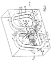
- Fig. 1 is a perspective view of a Coriolis type mass flowmeter.
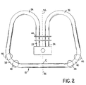
- Fig. 2 is side schematic view of the apparatus of Fig. 1.
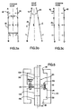
- Fig. 3 is a schematic representation of three modes of motion of the apparatus of Figs. 1 and 2.
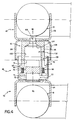
- Fig. 4 is a sectional view of an electromechanical driver according to the invention.
- FIG. 5 is a schematic representation of an alternative embodiment of the electromechanical driver of Fig. 4.
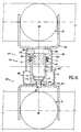
- FIG. 6 is a sectional view of an electromechanical sensor according to the invention.
- a specific tubular configuration is described herein in a perpendicular orientation with respect to the direction of the process flow, i.e., the direction of flow in a straight section of pipeline in which the material is to be inserted.
- the invention is equally applicable to in-line and other tubular configurations.
- the implementations illustrated herein are designed for flowmeters for a variety of products including petroleum based fuels, for example.
- the flowmeter and electromechanical driver described herein are applicable, of course, to a wide variety of other specific designs for the same or different applications.
- Fig. 1 illustrates a double loop, dual drive/detector system with mainly torsional loading of the tube ends where they are connected to a single rigid central manifold connected in line with the process flow. The same embodiment is shown in Figs. 1 and 2.
- the mass flowmeter 10 of Figs. 1 and 2 is designed to be inserted in a pipeline (not shown) which has had a small section removed or reserved to make room for the meter.
- the pipeline is equipped with opposing spaced flanges (not shown) which mate with mounting flanges 12 that are welded to short sections of pipe 14 connected to a central manifold block 16 supporting the two parallel planar loops 18 and 20.
- the configuration and shape of loops 18 and 20 are essentially identical. Thus, the description of the shape of loop 18 holds true for loop 20 as well, except where noted.
- Manifold block 16 is preferably a casting in the general shape of a solid rectangular block with a flat horizontal upper surface or top 21 and integral pipe sections 14.
- the ends of loop 18 comprise straight, preferably vertical, parallel inlet and outlet sections or legs 22 and 24 securely affixed, e.g., by butt welding, to the top of the manifold surface 21 in close proximity to each other.
- the base of loop 18 is a long straight section 26 passing beneath the bottom face of manifold block 16.
- the long straight section 26 at the base of the loop 18 is connected to upright legs 22 and 24 by respective diagonal sections 30 and 32.
- the four junctions between the various straight segments of the loop 28 are rounded by large radii turns to afford as little resistance to flow as possible.
- upright legs 22 and 24 are connected to the respective diagonal segments 30 and 32 by means of apex turns 34 and 36.
- the ends of the long straight base section 26 are connected to the respective ends of the diagonal segments 30 and 32 by lower rounded turns 38 and 40.
- the parallel inlet/outlet sections 22, 24 of both loops 18 and 20 pass through correspondingly apertured isolation plates or node plates 42 and 44 which are parallel to upper manifold surface 21 and spaced from the manifold surface by a predetermined distance.
- the node plates serve as stress isolation plates and define a common mechanical ground for each loop.
- Electromechanical driver and detector assemblies are attached between loops 18 and 20 on each of the lower rounded turns 38 and 40. Each assembly consists of an electromagnetic driver 46 and sensor 48 disposed closely to each other, between the tubes 18 and 20. The electrical signals are transferred from driver and detection circuitry (not shown) to the drivers and sensors through wire leads 50-53 which run along the exterior of the tubes, through apertured isolation plates 42 and 44, and are connected to an electrical socket 54.
- straight section 26 is caused to rotate about its co-planar perpendicular bisector 56 which intersects the tube at point c as shown in Fig. 2.
- the drive rotation is thus preferably in a horizontal plane about point c.
- the perpendicular bisectors for the straight sections of both loops preferably lie in a common plane of symmetry for both loops.
- each conduit loop oscillates around a point c.
- the two loops rotate synchronously but in the opposite sense, i.e., while loop 18 rotates clockwise, loop 20 undergoes counterclockwise rotation. That is, the loops are driven 180° out-of-phase about their respective points c. Consequently, respective ends such as A and C as shown in Fig. 3 periodically come together and go apart.
- This type of drive motion induces Coriolis effects in the directions shown in view 3a.
- the Coriolis mode motion thus tends to move the whole planes of the loops 18 and 20.
- the Coriolis effect is greatest when the two straight sections 26 are parallel as shown in view 3a, because the sinusoidally varying angular velocity is then at its maximum. Because the Coriolis mode motion of each loop is in the opposite direction, the straight sections 26 move slightly toward (or away) from each other as shown in view 3a. A common mode motion, undesirable in this instrument, would be one which deflected the loops in the same direction as shown in view 3c. This type of motion might be produced by an axial wave in the pipeline itself in the embodiment of Fig. 1 because the loops are oriented perpendicular to the pipeline.
- the sensors 48 detect the oscillatory motion of the straight sections of the tubes and output a signal that is representative of the oscillatory drive force modulated with the Coriolis reaction force exhibited by the fluid undergoing acceleration. Because of the close proximity of driver 46 and sensor 48, special precautions must be taken to prevent magnetic interlock from occurring. That is, the magnetic field from driver 46 may induce a voltage within the sensor 48 to give a spurious signal. It is preferred that a shielded driver and sensor be used to prevent magnetic interlock from occurring.
- driver assembly 46 of a preferred embodiment is shown.
- the shielded driver is designed to interconvert electrical and mechanical energy. Specifically, the driver efficiently converts electrical energy (i.e., electrical signals) into mechanical energy (that is, mechanical motion).
- Driver assembly 46 consists of a proximal end 62 attached to flow conduit 18 by a proximal mounting bracket 64 and a distal end 66 attached to flow conduit 20 by a distal mounting bracket 68.
- Proximal end 62 consists of a magnetic assembly 72 disposed within a proximal shield 70.
- the proximal shield is made of soft carbon steel and is cup-shaped having a cylindrical wall 71 and flat bottom 73 that is attached to proximal mounting bracket 64. The dimensions of the proximal shield are determined by the size and shape of the overall driver assembly.
- the proximal shield 70 acts as a magnetic path return, helping to contain the magnetic flux within the magnetic assembly.
- Disposed in the center of shield 70 is elongated magnet assembly 72 having a pair of magnets 75 and 76 separated by a central pole piece 78. The magnetic orientations of the magnets lie along the axis 80-80 defined by the driver assembly and point in opposite directions.
- magnets 75 and 76 are antiparallel.
- the magnets are oriented with the north poles of each magnet facing central pole piece 78. It will be appreciated by those skilled in the art that other orientations may be used, such as the south poles of each magnet facing the central pole piece.
- the pole piece may be made of any magnetically susceptible material, as is known in the art. A preferred material is soft carbon steel. This arrangement of magnets 75, 76 and central pole piece 78 concentrates the magnetic flux to within a small region proximate the pole piece for maximum interaction with a coil assembly 82.
- Distal end 66 of the driver assembly 60 consists of a coil assembly 82 disposed within a distal shield 84.
- the coil assembly comprises a coil carrier 86 which, on its distal end, is attached to distal shield 84 which is then attached to distal mounting bracket 68 by a nonmagnetic rivet 106 for connection to flow conduit 20.
- a bobbin 94 is integrally formed on the proximal end of the coil carrier 86.
- the coil carrier can be made from a nonconducting material to minimize the formation of eddy currents on the carrier itself.
- the bobbin 94 has wire wound 96 therearound to form an electromagnetic coil 98.
- the coil and coil carrier define an interior cavity 100 having a generally cylindrical section 102 and a frustoconical distal portion 104 that tapers from cylindrical section 102 to accommodate rivet 106.
- the generally cylindrical interior cavity is of a size sufficient to allow free movement of the magnet assembly and to allow maximum interaction between the coil assembly and the magnetic field projected from the magnet assembly.
- the proximal and distal shields are designed to move relative to each other and to minimize magnetic flux escape from the device. This is accomplished by forming the proximal and distal shields in a generally cylindrical overlapping shape such that one of the members can fit and move freely within the other. That is, the shields together form a telescoping arrangement wherein one of the shields fits within the other.
- the shielding members are cylindrical, and the proximal member has a smaller radius than the distal member and is adapted to fit within and move relative to the distal end along the axis 80-80 defined by the cylindrical shape of the shields. Together the shields minimize the leakage of magnetic flux from and into the device by providing a shielded and enclosed magnetic assembly.
- a cut (not shown) in the cylindrical surface of the distal shield can be used to prevent eddy current formation, which can increase magnetic flux.
- the absence of an external magnetic flux allows close placement of any number of drivers and sensors without the problem of magnetic interlock; the proximate drivers and sensors will not magnetically influence each other.
- Another benefit of this arrangement is the increase in linearity that results from the multiple magnet assembly. The movement of the proximal and distal ends relative to each other due to the driving current in the coil will not significantly alter the permanent magnetic field and consequently linear driving forces are achieved.
- the driver 110 consists of an elongated soft carbon steel shield 112 having a cylindrical cross section perpendicular to the member's axis 114-114.
- the shield has shoulder portions 116 and 118 that decrease the open area at each end of the shield and provide an opening through which an elongated magnetic member 120 moves.
- Located on the internal surface 122 of the shield is an annular ridge 124 projecting toward the center of the shield.
- An electromechanical coil 126 is mounted upon the annular ridge 124.
- Disposed centrally within the shield 112 is elongated magnetic member 120.
- Magnetic member 120 consists of two magnets 128 and 130 and three pole pieces 132, 134, and 136.
- central pole piece 132 Disposed on opposite sides of central pole piece 132 are two magnets 128 and 130 that have their magnetic orientations antiparallel, with respect to each other, and parallel to the axis 114-114 of the magnetic member.
- the north poles of each magnet 128 and 130 face each other.
- the south poles of each magnet may face each other.
- end pole pieces 134 and 136 On the ends of each magnet 128, 130 opposite pole piece 122, are attached end pole pieces 134 and 136 respectively. Together pole pieces 132, 134, and 136 and magnets 128 and 130 form an elongated magnet assembly which exhibits high efficiency and linearity.
- the design of the electromagnet device is based on the fact that maximum force should be provided from the driver with a minimum amount of current supplied to the coil.
- the embodiment of Fig. 5 consists of a soft carbon steel shell, 3 pole pieces, 2 permanent magnets and a coil.
- the aim of this embodiment is to focus the radial flux at the coil region and thus achieve maximum driving force for a given coil current.
- a finite element analysis program was used to calculate the coil inductance as well as the average radial flux in the coil area. This model was then used to optimize the electromagnet design to achieve maximum force for a set amount of current.
- the value used for the permeability of the soft carbon steel was 100, and that for the permanent magnet and air were 1.
- the remanence of the permanent magnet used was 0.9 tesla.
- the result of the calculation gave an average flux density of 477.2 millitesla.
- the coil inductance was also calculated by simulating the coil as a strip of permanent magnet located in the center of the assembly.
- the finite element program was run again to calculate the flux distribution due to the simulated coil.
- a regression program was then run to obtain a mathematical relation between the flux and the radial distance.
- An intrinsically safe mass flowmeter should have a low current limit in order to satisfy safety requirements so that this device will not be capable of igniting gas in a flammable environment.
- the value of the supplied current such as coil inductance, resistance, barrier resistance, supply voltage, cabling characteristics, etc.
- a large driving force is required if the tubes are thick and short (necessary for a compact design). This requires a high supplied current value which could violate the safety specification.
- the only alternative way to make the meter require a smaller force is to use long tubes with very thin walls. In this case the meter design will not be compact and will not be suitable for high pressure.
- the advantage of using the new design of the electromagnet device is apparent since it provides a large force with a small current and allows for construction of a relatively compact and sturdy device.
- a shielded sensor assembly 48 which is similar to driver 46, is shown in Fig. 6.
- the shielded sensor assembly like the shielded driver, is designed to interconvert electrical and mechanical energy. The sensor, however, efficiently converts mechanical energy (mechanical motion) into electrical energy (electrical signals), as opposed to the electromechanical driver.
- the shielded sensor assembly consists of a proximal end 152 attached to flow conduit 18 by a proximal mounting bracket 154, and a distal end 156 attached to flow conduit 20 by a distal mounting bracket 158.
- Proximal end 152 consists of a coil assembly 162′ positioned within a proximal shield 160 by a non-magnetic rivet 162.
- the shield is made of soft carbon steel and is cup shaped having a cylindrical wall 161 and a flat bottom 163 attached to proximal mounting bracket 154.
- the dimensions of the proximal shielding member is determined by the size and shape of the overall sensor assembly.
- On the distal end of the coil assembly is an integral bobbin 169 having wire wound therearound to form an electromagnetic coil 171.
- the coil assembly can be constructed from a non-magnetic material to prevent the formation of eddy currents.
- the coil assembly defines an interior cavity having generally cylindrical portions 170, 171 and frustoconical portions 172, 173, which taper from cylindrical portion 170 to opening 166 to accommodate rivet 162.
- the generally cylindrical interior cavity is large enough to allow free movement of the magnet assembly, but small to allow maximum interaction between the coil assembly and the magnetic field projected from a magnet assembly.
- Distal end 156 consists of a distal shielding member 176 and a magnetic assembly 178 disposed within the proximal shield.
- Shielding member 176 is made of soft carbon steel and is generally cup shaped having a cylindrical wall 180 and a flat bottom 182, which is attached to the distal mounting bracket 158. The dimensions of the distal shield are determined by the size and shape of the overall sensor assembly.
- Disposed in the center of shielding member 176 is an elongated magnet assembly 178 having a magnet 182 and pole piece 184. The magnetic orientation of the magnet lies along the axis 186-186 defined by the sensor assembly.
- the proximal and distal shielding members of the shielded sensor are designed to move relative to each other and to minimize magnetic flux escape out of and magnetic flux entrance into the device. This is accomplished by forming the proximal and distal shielding members in cylindrical shapes such that the shielding members together form a telescoping arrangement wherein one of the shielding members fits and moves within the other.
- the members are cylindrical and the distal shielding member has a smaller radius than the proximal shielding member and is adapted to fit within and move relative to the proximal shielding member along the axis.
- the shielding members minimize the leakage of magnetic flux of the device by providing a shielded and enclosed magnetic assembly. The absence of an external magnetic flux allows close placement of any number of drivers and sensors without the problem of interlock; the proximate drivers and sensors will not magnetically influence each other.
Landscapes
- Physics & Mathematics (AREA)
- Fluid Mechanics (AREA)
- General Physics & Mathematics (AREA)
- Measuring Volume Flow (AREA)
Applications Claiming Priority (3)
| Application Number | Priority Date | Filing Date | Title |
|---|---|---|---|
| US07/446,310 US5048350A (en) | 1989-12-05 | 1989-12-05 | Electromagnetic driver and sensor |
| US446310 | 1989-12-05 | ||
| PCT/US1990/007115 WO1991008448A1 (en) | 1989-12-05 | 1990-12-05 | Electromagnetic driver and sensor |
Publications (3)
| Publication Number | Publication Date |
|---|---|
| EP0456801A1 EP0456801A1 (en) | 1991-11-21 |
| EP0456801A4 EP0456801A4 (en) | 1992-03-18 |
| EP0456801B1 true EP0456801B1 (en) | 1995-02-15 |
Family
ID=23772107
Family Applications (1)
| Application Number | Title | Priority Date | Filing Date |
|---|---|---|---|
| EP91900532A Expired - Lifetime EP0456801B1 (en) | 1989-12-05 | 1990-12-05 | Electromagnetic driver and sensor |
Country Status (7)
| Country | Link |
|---|---|
| US (1) | US5048350A (enExample) |
| EP (1) | EP0456801B1 (enExample) |
| JP (1) | JPH07119640B2 (enExample) |
| CA (1) | CA2046658C (enExample) |
| DE (1) | DE69017008T2 (enExample) |
| RU (1) | RU2107263C1 (enExample) |
| WO (1) | WO1991008448A1 (enExample) |
Families Citing this family (24)
| Publication number | Priority date | Publication date | Assignee | Title |
|---|---|---|---|---|
| RU2155939C2 (ru) * | 1994-08-29 | 2000-09-10 | Микро Моушн, Инк. | Расходомер кориолиса и способ измерения расхода с использованием расходомера кориолиса (варианты) |
| US5546814A (en) * | 1994-10-26 | 1996-08-20 | The Foxboro Company | Parallel-flow coriolis-type mass flowmeter with flow-dividing manifold |
| USD369562S (en) | 1995-02-27 | 1996-05-07 | Tridelta Industries, Inc. | Pneumatic sensor |
| US6178828B1 (en) | 1998-02-11 | 2001-01-30 | Wade M. Mattar | Free standing Coriolis driver |
| US6286373B1 (en) * | 1999-02-12 | 2001-09-11 | Micro Motion, Inc. | Coriolis flowmeter having an explosion proof housing |
| EP1253409A1 (de) * | 2001-04-26 | 2002-10-30 | Endress + Hauser Flowtec AG | Magnetkreisanordnung für einen Messwertaufnehmer |
| US6805012B2 (en) * | 2002-07-26 | 2004-10-19 | Micro Motion, Inc. | Linear actuator |
| RU2316734C2 (ru) * | 2003-04-17 | 2008-02-10 | Майкро Моушн, Инк. | Способ и устройство для силового уравновешивания расходомера кориолиса |
| CA2522243C (en) | 2003-04-17 | 2011-10-11 | Micro Motion, Inc. | Method and apparatus for force balancing of a coriolis flow meter |
| MXPA06011730A (es) | 2004-04-16 | 2007-01-25 | Micro Motion Inc | Metodo y aparato para balanceo de fuerzas. |
| RU2351901C2 (ru) * | 2004-04-16 | 2009-04-10 | Майкро Моушн, Инк. | Способ и средство для балансировки |
| WO2006014153A1 (en) * | 2004-07-01 | 2006-02-09 | Micro Motion, Inc. | Split balance weights for eliminating density effect on flow |
| RU2348906C2 (ru) * | 2004-07-01 | 2009-03-10 | Майкро Моушн, Инк. | Разделенные уравновешивающие грузы для устранения влияния плотности на измерение расхода |
| DE102005060495B3 (de) * | 2005-12-15 | 2007-04-26 | Krohne Ag | Massendurchflußmeßgerät |
| JP5039650B2 (ja) | 2008-07-01 | 2012-10-03 | 株式会社キーエンス | 流量計 |
| DE102008035877A1 (de) * | 2008-08-01 | 2010-02-04 | Endress + Hauser Flowtec Ag | Meßwandler vom Vibrationstyp |
| DE102008037700A1 (de) | 2008-08-14 | 2010-02-18 | Endress + Hauser Flowtec Ag | Messaufnehmer vom Vibrationstyp |
| DE102008044186A1 (de) * | 2008-11-28 | 2010-06-02 | Endress + Hauser Flowtec Ag | Magneteinrichtung sowie Meßaufnehmer vom Vibrationstyp mit einer solchen Magneteinrichtung |
| JP5582737B2 (ja) | 2009-07-03 | 2014-09-03 | 株式会社キーエンス | コリオリ質量流量計 |
| JP5335583B2 (ja) | 2009-07-06 | 2013-11-06 | 株式会社キーエンス | コリオリ質量流量計 |
| DE102010018223A1 (de) * | 2010-04-23 | 2011-10-27 | Krohne Messtechnik Gmbh | Coriolis-Massedurchflussmessgerät |
| CN109425397B (zh) * | 2017-08-25 | 2023-10-27 | 罗凡 | 科里奥利质量流量计及其传感器组件 |
| CN119968548A (zh) * | 2022-09-30 | 2025-05-09 | 高准有限公司 | 流量计磁屏蔽设备和方法 |
| CN115565768B (zh) * | 2022-11-05 | 2023-08-22 | 北京首科实华自动化设备有限公司 | 科氏力质量流量计及其带磁场屏蔽的电磁系统 |
Family Cites Families (17)
| Publication number | Priority date | Publication date | Assignee | Title |
|---|---|---|---|---|
| US3142788A (en) * | 1964-07-28 | Reciprocating electromagnetic actu- | ||
| US2865201A (en) * | 1954-08-26 | 1958-12-23 | Roth Wilfred | Gyroscopic mass flowmeter |
| US3276257A (en) * | 1960-02-02 | 1966-10-04 | Roth Wilfred | Gyroscopic mass flowmeters |
| GB964923A (en) * | 1961-02-20 | 1964-07-29 | Wilfred Roth | Improvements in a temperature-regulated transducer |
| US4158959A (en) * | 1978-03-02 | 1979-06-26 | Camco, Incorporated | Apparatus for measuring the physical properties of material |
| US4233583A (en) * | 1978-09-22 | 1980-11-11 | Bicron Electronics Company | Flux shielded solenoid |
| US4468972A (en) * | 1982-04-19 | 1984-09-04 | Universal Cooperatives, Inc. | Flow meter with a motor driven impeller |
| DE3329544A1 (de) * | 1983-08-16 | 1985-03-07 | Karl Dipl.-Ing. 8060 Dachau Küppers | Massedurchflussmesser |
| US4655089A (en) * | 1985-06-07 | 1987-04-07 | Smith Meter Inc. | Mass flow meter and signal processing system |
| EP0235274B1 (en) * | 1985-08-29 | 1995-10-25 | Micro Motion Incorporated | Sensor mounting for vibrating structures |
| US4895031A (en) * | 1985-08-29 | 1990-01-23 | Micro Motion Inc. | Sensor mounting for coriolis mass flow rate meter |
| US4747312A (en) * | 1986-02-21 | 1988-05-31 | Fischer & Porter Co. | Double-loop Coriolis type mass flowmeter |
| US4738144A (en) * | 1986-10-03 | 1988-04-19 | Micro Motion, Inc. | Drive means for oscillating flow tubes of parallel path coriolis mass flow rate meter |
| DK171657B1 (da) * | 1986-10-14 | 1997-03-03 | Abb K Flow Inc | Massestrømsmåler af Coriolistypen og fremgangsmåde til måling af massestrøm |
| US4759223A (en) * | 1986-10-14 | 1988-07-26 | Saul Frost | Fluid mass flow meter |
| KR960000099B1 (ko) * | 1986-10-28 | 1996-01-03 | 더폭스보로 컴패니 | 코리올리 유형의 질량유량계 |
| JPS63281410A (ja) * | 1987-05-13 | 1988-11-17 | Mitsubishi Electric Corp | 磁気シ−ルド付電磁石 |
-
1989
- 1989-12-05 US US07/446,310 patent/US5048350A/en not_active Expired - Lifetime
-
1990
- 1990-12-05 CA CA002046658A patent/CA2046658C/en not_active Expired - Fee Related
- 1990-12-05 JP JP3-501120A patent/JPH07119640B2/ja not_active Expired - Lifetime
- 1990-12-05 WO PCT/US1990/007115 patent/WO1991008448A1/en not_active Ceased
- 1990-12-05 EP EP91900532A patent/EP0456801B1/en not_active Expired - Lifetime
- 1990-12-05 RU SU5001524A patent/RU2107263C1/ru active
- 1990-12-05 DE DE69017008T patent/DE69017008T2/de not_active Expired - Lifetime
Also Published As
| Publication number | Publication date |
|---|---|
| US5048350A (en) | 1991-09-17 |
| EP0456801A4 (en) | 1992-03-18 |
| WO1991008448A1 (en) | 1991-06-13 |
| EP0456801A1 (en) | 1991-11-21 |
| JPH07119640B1 (enExample) | 1995-12-20 |
| DE69017008D1 (de) | 1995-03-23 |
| JPH07119640B2 (ja) | 1995-12-20 |
| CA2046658C (en) | 1996-05-28 |
| RU2107263C1 (ru) | 1998-03-20 |
| CA2046658A1 (en) | 1991-06-06 |
| DE69017008T2 (de) | 1995-06-08 |
Similar Documents
| Publication | Publication Date | Title |
|---|---|---|
| EP0456801B1 (en) | Electromagnetic driver and sensor | |
| US5054326A (en) | Density compensator for coriolis-type mass flowmeters | |
| EP0783669B1 (en) | Stationary coils for a coriolis effect mass flowmeter | |
| US7464610B2 (en) | Coriolis flowmeter having a contactless excitation device | |
| US7143655B2 (en) | Magnetic circuit arrangement for a transducer | |
| CA1311943C (en) | Double-loop coriolis type flowmeter | |
| EP0210308B1 (en) | Mass flowmeter | |
| US4895031A (en) | Sensor mounting for coriolis mass flow rate meter | |
| KR100500553B1 (ko) | 축소된 크기를 가지는 대량 질량 유량용 코리올리 유량계 | |
| EP0332612B1 (en) | Ferromagnetic drive and velocity sensors for a coriolis mass flow rate meter | |
| US4628744A (en) | S-tube Coriolis force flow meter | |
| JPH04503574A (ja) | コリオリ型質量流量計及び該流量計に用いられる電気機械的装置 | |
| EP0421812B1 (en) | Improved coriolis-type flowmeter | |
| KR960000098B1 (ko) | 유량연속측정장치 | |
| US4635485A (en) | Precession flow meter | |
| JP2557098B2 (ja) | 対流慣性力流量計 | |
| US5131280A (en) | Vibrating conduit mass flowmeter | |
| Plache | Measuring mass flow using the Coriolis principle | |
| JP3767120B2 (ja) | 振動式測定装置 | |
| JPH1151733A (ja) | 振動式測定装置 | |
| JPH0441296Y2 (enExample) | ||
| JP2801849B2 (ja) | コリオリ流量計 | |
| JPH0441297Y2 (enExample) | ||
| JP2004294090A (ja) | 振動式測定装置 |
Legal Events
| Date | Code | Title | Description |
|---|---|---|---|
| PUAI | Public reference made under article 153(3) epc to a published international application that has entered the european phase |
Free format text: ORIGINAL CODE: 0009012 |
|
| 17P | Request for examination filed |
Effective date: 19910729 |
|
| AK | Designated contracting states |
Kind code of ref document: A1 Designated state(s): DE FR GB |
|
| A4 | Supplementary search report drawn up and despatched |
Effective date: 19920129 |
|
| AK | Designated contracting states |
Kind code of ref document: A4 Designated state(s): DE FR GB |
|
| 17Q | First examination report despatched |
Effective date: 19930604 |
|
| GRAA | (expected) grant |
Free format text: ORIGINAL CODE: 0009210 |
|
| AK | Designated contracting states |
Kind code of ref document: B1 Designated state(s): DE FR GB |
|
| REF | Corresponds to: |
Ref document number: 69017008 Country of ref document: DE Date of ref document: 19950323 |
|
| ET | Fr: translation filed | ||
| PLBE | No opposition filed within time limit |
Free format text: ORIGINAL CODE: 0009261 |
|
| STAA | Information on the status of an ep patent application or granted ep patent |
Free format text: STATUS: NO OPPOSITION FILED WITHIN TIME LIMIT |
|
| 26N | No opposition filed | ||
| REG | Reference to a national code |
Ref country code: GB Ref legal event code: IF02 |
|
| PGFP | Annual fee paid to national office [announced via postgrant information from national office to epo] |
Ref country code: GB Payment date: 20021104 Year of fee payment: 13 |
|
| PGFP | Annual fee paid to national office [announced via postgrant information from national office to epo] |
Ref country code: FR Payment date: 20021202 Year of fee payment: 13 |
|
| PG25 | Lapsed in a contracting state [announced via postgrant information from national office to epo] |
Ref country code: GB Free format text: LAPSE BECAUSE OF NON-PAYMENT OF DUE FEES Effective date: 20031205 |
|
| GBPC | Gb: european patent ceased through non-payment of renewal fee |
Effective date: 20031205 |
|
| PG25 | Lapsed in a contracting state [announced via postgrant information from national office to epo] |
Ref country code: FR Free format text: LAPSE BECAUSE OF NON-PAYMENT OF DUE FEES Effective date: 20040831 |
|
| REG | Reference to a national code |
Ref country code: FR Ref legal event code: ST |
|
| PGFP | Annual fee paid to national office [announced via postgrant information from national office to epo] |
Ref country code: DE Payment date: 20091230 Year of fee payment: 20 |
|
| PG25 | Lapsed in a contracting state [announced via postgrant information from national office to epo] |
Ref country code: DE Free format text: LAPSE BECAUSE OF EXPIRATION OF PROTECTION Effective date: 20101205 |