EP0456534B1 - System und Verfahren zum Zusammenbau einer Orthese - Google Patents
System und Verfahren zum Zusammenbau einer Orthese Download PDFInfo
- Publication number
- EP0456534B1 EP0456534B1 EP91400962A EP91400962A EP0456534B1 EP 0456534 B1 EP0456534 B1 EP 0456534B1 EP 91400962 A EP91400962 A EP 91400962A EP 91400962 A EP91400962 A EP 91400962A EP 0456534 B1 EP0456534 B1 EP 0456534B1
- Authority
- EP
- European Patent Office
- Prior art keywords
- cavity
- vertical member
- sleeve
- branch
- faces
- Prior art date
- Legal status (The legal status is an assumption and is not a legal conclusion. Google has not performed a legal analysis and makes no representation as to the accuracy of the status listed.)
- Expired - Lifetime
Links
- 238000004519 manufacturing process Methods 0.000 title claims description 3
- 238000000034 method Methods 0.000 title claims description 3
- 239000000853 adhesive Substances 0.000 claims abstract description 6
- 230000001070 adhesive effect Effects 0.000 claims abstract description 6
- 210000003141 lower extremity Anatomy 0.000 claims abstract description 6
- 210000001364 upper extremity Anatomy 0.000 claims abstract description 6
- 239000000463 material Substances 0.000 claims abstract description 5
- 239000007787 solid Substances 0.000 claims abstract description 5
- 239000007788 liquid Substances 0.000 claims description 7
- 235000011837 pasties Nutrition 0.000 claims description 7
- 239000000047 product Substances 0.000 claims description 6
- 239000012265 solid product Substances 0.000 claims description 2
- 210000002414 leg Anatomy 0.000 description 8
- 239000000178 monomer Substances 0.000 description 4
- 229920000642 polymer Polymers 0.000 description 4
- 210000000617 arm Anatomy 0.000 description 2
- 210000003414 extremity Anatomy 0.000 description 2
- 210000000245 forearm Anatomy 0.000 description 2
- 210000000689 upper leg Anatomy 0.000 description 2
- 241001080024 Telles Species 0.000 description 1
- PNEYBMLMFCGWSK-UHFFFAOYSA-N aluminium oxide Inorganic materials [O-2].[O-2].[O-2].[Al+3].[Al+3] PNEYBMLMFCGWSK-UHFFFAOYSA-N 0.000 description 1
- 239000004568 cement Substances 0.000 description 1
- 230000000694 effects Effects 0.000 description 1
- 239000003822 epoxy resin Substances 0.000 description 1
- 210000003127 knee Anatomy 0.000 description 1
- 239000013528 metallic particle Substances 0.000 description 1
- 239000002245 particle Substances 0.000 description 1
- 229920000647 polyepoxide Polymers 0.000 description 1
- 230000000379 polymerizing effect Effects 0.000 description 1
- 229920005989 resin Polymers 0.000 description 1
- 239000011347 resin Substances 0.000 description 1
- 238000010008 shearing Methods 0.000 description 1
- 125000006850 spacer group Chemical group 0.000 description 1
Images
Classifications
-
- A—HUMAN NECESSITIES
- A61—MEDICAL OR VETERINARY SCIENCE; HYGIENE
- A61F—FILTERS IMPLANTABLE INTO BLOOD VESSELS; PROSTHESES; DEVICES PROVIDING PATENCY TO, OR PREVENTING COLLAPSING OF, TUBULAR STRUCTURES OF THE BODY, e.g. STENTS; ORTHOPAEDIC, NURSING OR CONTRACEPTIVE DEVICES; FOMENTATION; TREATMENT OR PROTECTION OF EYES OR EARS; BANDAGES, DRESSINGS OR ABSORBENT PADS; FIRST-AID KITS
- A61F5/00—Orthopaedic methods or devices for non-surgical treatment of bones or joints; Nursing devices ; Anti-rape devices
- A61F5/01—Orthopaedic devices, e.g. long-term immobilising or pressure directing devices for treating broken or deformed bones such as splints, casts or braces
- A61F5/0102—Orthopaedic devices, e.g. long-term immobilising or pressure directing devices for treating broken or deformed bones such as splints, casts or braces specially adapted for correcting deformities of the limbs or for supporting them; Ortheses, e.g. with articulations
- A61F5/0123—Orthopaedic devices, e.g. long-term immobilising or pressure directing devices for treating broken or deformed bones such as splints, casts or braces specially adapted for correcting deformities of the limbs or for supporting them; Ortheses, e.g. with articulations for the knees
- A61F5/0125—Orthopaedic devices, e.g. long-term immobilising or pressure directing devices for treating broken or deformed bones such as splints, casts or braces specially adapted for correcting deformities of the limbs or for supporting them; Ortheses, e.g. with articulations for the knees the device articulating around a single pivot-point
-
- A—HUMAN NECESSITIES
- A61—MEDICAL OR VETERINARY SCIENCE; HYGIENE
- A61F—FILTERS IMPLANTABLE INTO BLOOD VESSELS; PROSTHESES; DEVICES PROVIDING PATENCY TO, OR PREVENTING COLLAPSING OF, TUBULAR STRUCTURES OF THE BODY, e.g. STENTS; ORTHOPAEDIC, NURSING OR CONTRACEPTIVE DEVICES; FOMENTATION; TREATMENT OR PROTECTION OF EYES OR EARS; BANDAGES, DRESSINGS OR ABSORBENT PADS; FIRST-AID KITS
- A61F5/00—Orthopaedic methods or devices for non-surgical treatment of bones or joints; Nursing devices ; Anti-rape devices
- A61F5/01—Orthopaedic devices, e.g. long-term immobilising or pressure directing devices for treating broken or deformed bones such as splints, casts or braces
- A61F5/0102—Orthopaedic devices, e.g. long-term immobilising or pressure directing devices for treating broken or deformed bones such as splints, casts or braces specially adapted for correcting deformities of the limbs or for supporting them; Ortheses, e.g. with articulations
-
- F—MECHANICAL ENGINEERING; LIGHTING; HEATING; WEAPONS; BLASTING
- F16—ENGINEERING ELEMENTS AND UNITS; GENERAL MEASURES FOR PRODUCING AND MAINTAINING EFFECTIVE FUNCTIONING OF MACHINES OR INSTALLATIONS; THERMAL INSULATION IN GENERAL
- F16B—DEVICES FOR FASTENING OR SECURING CONSTRUCTIONAL ELEMENTS OR MACHINE PARTS TOGETHER, e.g. NAILS, BOLTS, CIRCLIPS, CLAMPS, CLIPS OR WEDGES; JOINTS OR JOINTING
- F16B11/00—Connecting constructional elements or machine parts by sticking or pressing them together, e.g. cold pressure welding
- F16B11/006—Connecting constructional elements or machine parts by sticking or pressing them together, e.g. cold pressure welding by gluing
Definitions
- the present invention relates to a new system for assembling an upright and an articulation of an orthosis of the upper or lower limbs.
- the invention also relates to a method for producing such an assembly system.
- such orthoses used at the elbow or knee of patients, generally include two longitudinal uprights, arranged outside each of the limbs (arms and forearms, or leg and thigh) and joined by spacers curved or "embraces" following the transverse profile of the limb, each of the uprights associated with the arms and forearms or the thigh and the leg being articulated together by an articulation comprising two pivoting branches about an axis, this articulation comprising possibly a locking element in position.
- the two branches of the articulation often have the shape of a sheath, in which is engaged the corresponding end of the associated upright, the branch of the articulation and the upright being rigidly secured to each other at l using at least one screw.
- each upright Before being made integral with the joint, each upright must be oriented with great precision with respect to the axis thereof and, when one simply fits the end of the upright into the associated sleeve of the joint , the resulting positioning is very often of insufficient precision.
- the present invention aims to remedy this drawback by proposing an assembly system in a precise relative position of the uprights and the joints of such an orthosis.
- the invention also aims to provide a system of this type which can be easily carried out using the usual means in the art.
- the invention finally aims to provide orthotics comprising such an assembly system and having a high mechanical strength in the assembly of the uprights and the joints.
- the subject of the invention is a system for assembling an upright of an orthosis of the lower or upper limbs and of a branch of a joint with two branches pivotally mounted about an axis one relative to the other, system in which the branch of the articulation forms a sheath in the cavity of which is engaged the end of the associated upright, this end and the branch of the sheath being made rigidly integral with one another by at least one screw arranged perpendicular to the lateral faces of the uprights, this assembly system being characterized in that the end of the upright engaged in the cavity of the sleeve is not in contact with the bottom of this cavity, in that its large faces have a width less than that of the corresponding dimension of the cavity of the sheath, while the same faces of this amount external to this cavity have a width greater than that of the corresponding dimension nte of the opening of the sleeve, so that the upright is supported laterally by its sides perpendicular to the large faces against the corresponding parts of the opening of the slee
- the amount of the orthosis and the associated branch of the joint are therefore secured, on the one hand, by the screw of the prior art, on the other hand, by the solid adhesive material, for example a polymer, an adhesive or a cement filling the cavity of the sheath. Due to this double connection, no breaking stress will be exerted on the screw. In addition, the amount coming to abut laterally by its sides against the corresponding parts of the opening of the cavity while its end does not touch the bottom of this cavity, it will be possible to orient it precisely with respect to the branch of the sheath, before secure it using at least one screw and at least one liquid or pasty monomer (a resin) which is then polymerized.
- the solid adhesive material for example a polymer, an adhesive or a cement filling the cavity of the sheath. Due to this double connection, no breaking stress will be exerted on the screw.
- the amount coming to abut laterally by its sides against the corresponding parts of the opening of the cavity while its end does not touch the bottom of this cavity it
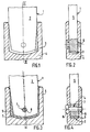
- the end of the upright 1 has a width less than that of the cavity 3, while the part of the upright external to the cavity 3 has a width greater than that of the opening of this cavity.
- This upright 1 can thus rest on its sides 5 against the corresponding edges of the opening of the cavity 3.
- the longitudinal dimension of the end of the upright engaged in the cavity 3 is such that this end does not touch the bottom of the cavity. It is thus possible to rotate the upright 1 relative to the branch 4 in order to orient it precisely in the desired position, for example that which appears in FIG. 3.
- the branch 4 is pierced transversely with a screw hole 6 and, when the amount is in the desired position relative to the branch 4, this amount is drilled with an identical screw hole opposite the hole 6. If the branch was not drilled in advance with a screw hole, the upright 1 and the branch 4 would be pierced simultaneously with screw holes arranged opposite, after having brought the upright 1 into the desired position.
- the end of the upright 1 is then removed from the cavity 3 and this cavity is filled with a monomer capable of polymerizing, giving a solid polymer, which adheres to the material of which the upright 1 and the branch 4 are made.
- a monomer capable of polymerizing giving a solid polymer, which adheres to the material of which the upright 1 and the branch 4 are made.
- the amount 1 is then reintroduced into the cavity 3, causing the overflow of the monomer to overflow, which is eliminated.
- the screw holes 6 and 7 are brought opposite one another, which has the effect of bringing the upright 1 into the precise position desired relative to the branch 4 of the joint, and, in this position ( Figure 3), the upright 1 and the branch 4 are secured with a screw 8 screwed into the holes 6 and 7.
- the means used to achieve this assembly in a relative position defined with precision of the amount 1 of the branch 4 of the joint are simple means, well known in the art, and this does not result in any increase in the cost of the orthosis thus carried out.
Landscapes
- Health & Medical Sciences (AREA)
- Engineering & Computer Science (AREA)
- Vascular Medicine (AREA)
- General Health & Medical Sciences (AREA)
- Nursing (AREA)
- Orthopedic Medicine & Surgery (AREA)
- Biomedical Technology (AREA)
- Heart & Thoracic Surgery (AREA)
- General Engineering & Computer Science (AREA)
- Life Sciences & Earth Sciences (AREA)
- Animal Behavior & Ethology (AREA)
- Veterinary Medicine (AREA)
- Public Health (AREA)
- Mechanical Engineering (AREA)
- Orthopedics, Nursing, And Contraception (AREA)
- Prostheses (AREA)
- Joining Of Building Structures In Genera (AREA)
- Food-Manufacturing Devices (AREA)
- Paper (AREA)
Claims (2)
- System zur Verbindung einer Strebe (1) einer Prothese für die unteren oder oberen Gliedmaßen und eines Schenkels (4) eines Gelenkes mit zwei Schenkeln, die zueinander um eine Achse drehbar angeordnet sind, ein System, in dem der Schenkel (1) des Gelenkes eine Hülse bildet, in deren Hohlraum (3) das Ende der zugehörigen Strebe (1) eingeführt ist und dieses Ende und der Schenkel der Hülse mit Hilfe mindestens einer Schraube (8) fest miteinander verbunden werden, die senkrecht zu den Seitenflächen der Streben angeordnet ist, wobei dieses Verbindungssystem dadurch gekennzeichnet ist, daß das Ende der in den Hohlraum (3) der Hülse eingreifenden Strebe (1) den Boden dieses Hohlraumes nicht berührt, daß ihre großen Seiten (2) von einer geringeren Breite als das entsprechende Maß des Hohlraumes sind, während die gleichen Seiten (2) dieser Strebe außerhalb dieses Hohlraumes breiter als das entsprechende Maß der Öffnung der Hülse sind, damit die Strebe (1) mit ihren zu den großen Seiten (2) senkrechten Flanken (5) seitlich auf den entsprechenden Teilen der Öffnung der Hülse aufliegt, und dadurch, daß das Ende der in den Hohlraum (3) der Hülse eingreifenden Strebe in einen festen Klebstoff (9) eingelassen ist, der diesen Hohlraum ausfüllt und an dessen Innenflächen sowie den Außenflächen des Endes der Strebe (1) haftet.
- Ein Verfahren zur Herstellung eines Verbindungssystems nach Anspruch 1 einer Strebe (1) einer Prothese der unteren oder oberen Gliedmaßen und eines Schenkels (4) eines Gelenkes mit zwei zueinander um eine Achse drehbar angeordneten Schenkeln, durch die folgenden, nacheinander auszuführenden Schritte gekennzeichnet:- in den Hohlraum (3) des Schenkels (4), der die Hülse des Gelenkes bildet und durch die eventuell quer ein Loch für eine Schraube (6) verläuft, wird ein Ende der Strebe (1) eingeführt, dessen Breite der großen Seiten (2) kleiner als das entsprechende Maß des Hohlraumes (3) ist, während die gleichen Seiten (2) der Strebe (1) außerhalb des Hohlraumes (3) breiter als das entsprechende Maß der Öffnung der Hülse sind, damit die Strebe mit ihren Flanken (5) senkrecht zu den großen Seiten (2) auf den entsprechenden Teilen der Öffnung des Hohlraumes aufliegt, wobei die Abmessungen des in die Hülse eingeführten Teils so sind, daß das Ende der Strebe (1) den Boden des Hohlraumes (3) nicht berührt;- die Strebe (1) wird in bezug auf den Schenkel (4) des Gelenkes präzise ausgerichtet;- es werden gegenüberliegende Löcher für Schrauben (7) in die in dieser Position gehaltene Strebe und in den Schenkel, der die Hülse des Gelenkes bildet, oder nur in die Strebe gegenüber dem Loch für die Schraube (6) gebohrt, das eventuell bereits in dem Schenkel, der die Hülse bildet, enthalten ist;- das Ende der Strebe (1) wird aus der Hülse gezogen;- der Hohlraum (3) der Hülse wird mindestens mit einem flüssigen und breiartigen Produkt gefüllt, das zu einem festen Produkt aushärten kann, das an den Innenwänden des genannten Hohlraumes haftet;- in diesen Hohlraum (3) wird das Ende der Strebe (1) erneut eingeführt, indem das überflüssige flüssige oder breiartige Produkt aus dem Hohlraum entfernt wird;- die in die Strebe und den Schenkel, welche die Hülse des Gelenkes bilden, gebohrten Löcher (6,7) werden gegenüberliegend ausgerichtet;- das Ende der Strebe (1) und des Schenkels (4), welche die Hülse bilden, werden mit einer in diese Löcher eingeführten Schraube (8) verbunden;- das flüssige oder breiartige Produkt wird zum Aushärten gebracht.
Priority Applications (1)
| Application Number | Priority Date | Filing Date | Title |
|---|---|---|---|
| AT91400962T ATE100697T1 (de) | 1990-05-10 | 1991-04-10 | System und verfahren zum zusammenbau einer orthese. |
Applications Claiming Priority (2)
| Application Number | Priority Date | Filing Date | Title |
|---|---|---|---|
| FR9005817A FR2661818B1 (fr) | 1990-05-10 | 1990-05-10 | Nouveau systeme d'assemblage d'un montant et d'une articulation d'une orhtese des membres superieurs ou inferieurs et procede pour la realisation d'un tel systeme d'assemblage. |
| FR9005817 | 1990-05-10 |
Publications (2)
| Publication Number | Publication Date |
|---|---|
| EP0456534A1 EP0456534A1 (de) | 1991-11-13 |
| EP0456534B1 true EP0456534B1 (de) | 1994-01-26 |
Family
ID=9396459
Family Applications (1)
| Application Number | Title | Priority Date | Filing Date |
|---|---|---|---|
| EP91400962A Expired - Lifetime EP0456534B1 (de) | 1990-05-10 | 1991-04-10 | System und Verfahren zum Zusammenbau einer Orthese |
Country Status (4)
| Country | Link |
|---|---|
| EP (1) | EP0456534B1 (de) |
| AT (1) | ATE100697T1 (de) |
| DE (1) | DE69101077T2 (de) |
| FR (1) | FR2661818B1 (de) |
Families Citing this family (1)
| Publication number | Priority date | Publication date | Assignee | Title |
|---|---|---|---|---|
| CN111015543B (zh) * | 2019-11-25 | 2021-04-20 | 北京北机机电工业有限责任公司 | 一种筒形零件粘接工装 |
Family Cites Families (3)
| Publication number | Priority date | Publication date | Assignee | Title |
|---|---|---|---|---|
| US4561670A (en) * | 1982-05-28 | 1985-12-31 | Honda Giken Kogyo Kabushiki Kaisha | Frame for automated two-wheel vehicles, and method for its manufacture |
| US4502472A (en) * | 1983-09-12 | 1985-03-05 | Pansiera Timothy T | Hinge means for orthopedic brace |
| DE3635031A1 (de) * | 1986-10-15 | 1988-04-21 | Halberg Maschbau Gmbh & Co | Verfahren zum verbinden von gussstuecken |
-
1990
- 1990-05-10 FR FR9005817A patent/FR2661818B1/fr not_active Expired - Lifetime
-
1991
- 1991-04-10 DE DE69101077T patent/DE69101077T2/de not_active Expired - Fee Related
- 1991-04-10 AT AT91400962T patent/ATE100697T1/de not_active IP Right Cessation
- 1991-04-10 EP EP91400962A patent/EP0456534B1/de not_active Expired - Lifetime
Also Published As
| Publication number | Publication date |
|---|---|
| FR2661818B1 (fr) | 1992-10-30 |
| DE69101077D1 (de) | 1994-03-10 |
| DE69101077T2 (de) | 1994-05-26 |
| ATE100697T1 (de) | 1994-02-15 |
| EP0456534A1 (de) | 1991-11-13 |
| FR2661818A1 (fr) | 1991-11-15 |
Similar Documents
| Publication | Publication Date | Title |
|---|---|---|
| FR2557668A1 (fr) | Assemblage d'un connecteur, element tubulaire et procede de realisation d'un raccord entre deux elements tubulaires | |
| FR2714709A1 (fr) | Accouplement à ouverture d'urgence alimenté par une double vanne à boisseau sphérique à débordement nul. | |
| FR2640499A1 (fr) | Nouvelle structure de pied prothetique | |
| FR2467348A1 (fr) | Raccord de canalisation comprenant un collier a chaine | |
| FR2965199A1 (fr) | Bride d'aide au travail de tubes comportant plusieurs parties. | |
| EP3851725B1 (de) | Schelle mit einem durchmesserverstellsystem derart eingerichtet, um eine änderung im durchmesser der schelle zu erlauben | |
| FR2483540A1 (fr) | Verin pneumatique ou hydraulique | |
| FR3053956B1 (fr) | Gouverne crocodile pour aeronef | |
| EP0456534B1 (de) | System und Verfahren zum Zusammenbau einer Orthese | |
| WO1992007144A1 (fr) | Procede de construction d'ouvrages d'art comprenant une voute et elements prefabriques pour la mise en ×uvre de ce procede | |
| FR2528900A1 (fr) | Charniere lisse | |
| FR2587971A1 (fr) | Rotor, en particulier pour aeronef a voilure tournante | |
| FR2640336A1 (fr) | Ecrou rapide | |
| EP0220095B1 (de) | Verfahren und Vorrichtung zum Ausrichten und Anpassen eines ersten Teiles aus Kunststoff, das beispielsweise thermoverschweissbar mit einem zweiten ähnlichen Kunststoffteil ist, welches ebenfalls im Hinblick auf das Verbinden der Enden ausgerichtet werden kann | |
| FR2564019A1 (fr) | Pince d'alignement interne | |
| FR2581717A1 (fr) | Raccord pour l'assemblage angulaire d'organes tubulaires | |
| EP0124430B1 (de) | Kupplungsvorrichtung mit Fernauslösung | |
| FR2760264A1 (fr) | Dispositif d'etanchement | |
| EP0262998A1 (de) | Bohrvorrichtung für Holzpaneele und ihr Zusammenbau durch Dübeln | |
| FR2638088A1 (fr) | Dispositif pour relever la configuration d'un membre inferieur du corps humain en vue de la realisation d'une orthese pour paraplegique | |
| EP0410842A1 (de) | Schnellkupplung | |
| EP0953778A1 (de) | Schnellmontagemutter bestehend aus zwei Mutterhälften, und Befestigungsvorrichtung insbesondere für Betonschalung mit Verwendung dieser Mutter | |
| EP0217901A1 (de) | Kupplung und entkupplung mit sicherheitsverriegelung und öffnung durch kraftzylinder unterstützt | |
| FR2719455A1 (fr) | Mannequin représentant le corps d'un être humain. | |
| WO1985000634A1 (fr) | Pince de puissance pour le vissage des tiges de forage |
Legal Events
| Date | Code | Title | Description |
|---|---|---|---|
| PUAI | Public reference made under article 153(3) epc to a published international application that has entered the european phase |
Free format text: ORIGINAL CODE: 0009012 |
|
| AK | Designated contracting states |
Kind code of ref document: A1 Designated state(s): AT BE DE GB IT NL SE |
|
| 17P | Request for examination filed |
Effective date: 19920206 |
|
| 17Q | First examination report despatched |
Effective date: 19930712 |
|
| GRAA | (expected) grant |
Free format text: ORIGINAL CODE: 0009210 |
|
| AK | Designated contracting states |
Kind code of ref document: B1 Designated state(s): AT BE DE GB IT NL SE |
|
| REF | Corresponds to: |
Ref document number: 100697 Country of ref document: AT Date of ref document: 19940215 Kind code of ref document: T |
|
| GBT | Gb: translation of ep patent filed (gb section 77(6)(a)/1977) |
Effective date: 19940209 |
|
| REF | Corresponds to: |
Ref document number: 69101077 Country of ref document: DE Date of ref document: 19940310 |
|
| ITF | It: translation for a ep patent filed | ||
| PLBE | No opposition filed within time limit |
Free format text: ORIGINAL CODE: 0009261 |
|
| STAA | Information on the status of an ep patent application or granted ep patent |
Free format text: STATUS: NO OPPOSITION FILED WITHIN TIME LIMIT |
|
| 26N | No opposition filed | ||
| EAL | Se: european patent in force in sweden |
Ref document number: 91400962.6 |
|
| REG | Reference to a national code |
Ref country code: GB Ref legal event code: IF02 |
|
| PGFP | Annual fee paid to national office [announced via postgrant information from national office to epo] |
Ref country code: GB Payment date: 20030415 Year of fee payment: 13 |
|
| PGFP | Annual fee paid to national office [announced via postgrant information from national office to epo] |
Ref country code: SE Payment date: 20030417 Year of fee payment: 13 |
|
| PGFP | Annual fee paid to national office [announced via postgrant information from national office to epo] |
Ref country code: AT Payment date: 20030418 Year of fee payment: 13 |
|
| PGFP | Annual fee paid to national office [announced via postgrant information from national office to epo] |
Ref country code: NL Payment date: 20030423 Year of fee payment: 13 |
|
| PGFP | Annual fee paid to national office [announced via postgrant information from national office to epo] |
Ref country code: BE Payment date: 20030512 Year of fee payment: 13 |
|
| PG25 | Lapsed in a contracting state [announced via postgrant information from national office to epo] |
Ref country code: GB Free format text: LAPSE BECAUSE OF NON-PAYMENT OF DUE FEES Effective date: 20040410 Ref country code: AT Free format text: LAPSE BECAUSE OF NON-PAYMENT OF DUE FEES Effective date: 20040410 |
|
| PG25 | Lapsed in a contracting state [announced via postgrant information from national office to epo] |
Ref country code: SE Free format text: LAPSE BECAUSE OF NON-PAYMENT OF DUE FEES Effective date: 20040411 |
|
| PG25 | Lapsed in a contracting state [announced via postgrant information from national office to epo] |
Ref country code: BE Free format text: LAPSE BECAUSE OF NON-PAYMENT OF DUE FEES Effective date: 20040430 |
|
| BERE | Be: lapsed |
Owner name: ETS *PROTEOR Effective date: 20040430 |
|
| PG25 | Lapsed in a contracting state [announced via postgrant information from national office to epo] |
Ref country code: NL Free format text: LAPSE BECAUSE OF NON-PAYMENT OF DUE FEES Effective date: 20041101 |
|
| EUG | Se: european patent has lapsed | ||
| GBPC | Gb: european patent ceased through non-payment of renewal fee |
Effective date: 20040410 |
|
| NLV4 | Nl: lapsed or anulled due to non-payment of the annual fee |
Effective date: 20041101 |
|
| PG25 | Lapsed in a contracting state [announced via postgrant information from national office to epo] |
Ref country code: IT Free format text: LAPSE BECAUSE OF NON-PAYMENT OF DUE FEES;WARNING: LAPSES OF ITALIAN PATENTS WITH EFFECTIVE DATE BEFORE 2007 MAY HAVE OCCURRED AT ANY TIME BEFORE 2007. THE CORRECT EFFECTIVE DATE MAY BE DIFFERENT FROM THE ONE RECORDED. Effective date: 20050410 |
|
| PGFP | Annual fee paid to national office [announced via postgrant information from national office to epo] |
Ref country code: DE Payment date: 20070423 Year of fee payment: 17 |
|
| PG25 | Lapsed in a contracting state [announced via postgrant information from national office to epo] |
Ref country code: DE Free format text: LAPSE BECAUSE OF NON-PAYMENT OF DUE FEES Effective date: 20081101 |