EP0456145A1 - Conveyor belt - Google Patents
Conveyor belt Download PDFInfo
- Publication number
- EP0456145A1 EP0456145A1 EP91107284A EP91107284A EP0456145A1 EP 0456145 A1 EP0456145 A1 EP 0456145A1 EP 91107284 A EP91107284 A EP 91107284A EP 91107284 A EP91107284 A EP 91107284A EP 0456145 A1 EP0456145 A1 EP 0456145A1
- Authority
- EP
- European Patent Office
- Prior art keywords
- conveyor belt
- chain
- support rods
- chains
- belt according
- Prior art date
- Legal status (The legal status is an assumption and is not a legal conclusion. Google has not performed a legal analysis and makes no representation as to the accuracy of the status listed.)
- Withdrawn
Links
Images
Classifications
-
- B—PERFORMING OPERATIONS; TRANSPORTING
- B65—CONVEYING; PACKING; STORING; HANDLING THIN OR FILAMENTARY MATERIAL
- B65G—TRANSPORT OR STORAGE DEVICES, e.g. CONVEYORS FOR LOADING OR TIPPING, SHOP CONVEYOR SYSTEMS OR PNEUMATIC TUBE CONVEYORS
- B65G17/00—Conveyors having an endless traction element, e.g. a chain, transmitting movement to a continuous or substantially-continuous load-carrying surface or to a series of individual load-carriers; Endless-chain conveyors in which the chains form the load-carrying surface
- B65G17/06—Conveyors having an endless traction element, e.g. a chain, transmitting movement to a continuous or substantially-continuous load-carrying surface or to a series of individual load-carriers; Endless-chain conveyors in which the chains form the load-carrying surface having a load-carrying surface formed by a series of interconnected, e.g. longitudinal, links, plates, or platforms
- B65G17/063—Conveyors having an endless traction element, e.g. a chain, transmitting movement to a continuous or substantially-continuous load-carrying surface or to a series of individual load-carriers; Endless-chain conveyors in which the chains form the load-carrying surface having a load-carrying surface formed by a series of interconnected, e.g. longitudinal, links, plates, or platforms the load carrying surface being formed by profiles, rods, bars, rollers or the like attached to more than one traction element
-
- B—PERFORMING OPERATIONS; TRANSPORTING
- B65—CONVEYING; PACKING; STORING; HANDLING THIN OR FILAMENTARY MATERIAL
- B65G—TRANSPORT OR STORAGE DEVICES, e.g. CONVEYORS FOR LOADING OR TIPPING, SHOP CONVEYOR SYSTEMS OR PNEUMATIC TUBE CONVEYORS
- B65G2201/00—Indexing codes relating to handling devices, e.g. conveyors, characterised by the type of product or load being conveyed or handled
- B65G2201/06—Articles and bulk
Definitions
- the invention relates to a conveyor belt, which consists of at least two parallel, endlessly rotating chains driven by sprockets, each with a number of overlapping chain links and a number of support bars arranged transversely to the chains, the ends of the support bars as hinge pins for the Serving chain links penetrate them and the intermediate area of the support rods serves as the support area of the conveyor belt.
- Such conveyor belts are known and are used in particular in the industrial sector for internal transport tasks.
- the support rods arranged between the chains are designed such that they rest on the chain links and are guided across them.
- Their U-shaped bent ends penetrate the chain links from the outside.
- the drive takes place in a straight line on both sides via sprockets, in curves is due to the compression Chain links of the chain lying on the inside of the curve can only be driven on one side on the chain lying on the outside radius of the curve.
- the object of the present invention is to create a conveyor belt of the type mentioned at the outset which ensures reliable, low-wear operation.
- a conveyor belt of the type mentioned which is characterized in that two chains running side by side as a double chain form one long side of the conveyor belt, that a third chain as a single chain forms the other long side of the conveyor belt, that the double chain one has a fixed pitch and that the individual chain has a variable pitch with chain links which are displaceable to a limited extent in the longitudinal direction of the conveyor belt.
- the double chain advantageously enables a space-saving, inexpensive one-sided drive on straight conveyor belt sections via a chain wheel designed as a double wheel with only one common drive unit, without risk of overloading.
- the fixed division of the double chain on the inner radius of the curve as well as the variable division of the single chain, which adapts to the enlarged outer radius, enable a powerful drive on both sides, thereby avoiding the one-sided overstressing that previously occurred.
- the supporting bars can be covered with a mesh in the supporting area in order to enable the transport of pressure-sensitive goods or goods of small size that would otherwise fall through between the supporting bars.
- the first exemplary embodiment of the conveyor belt 1 shown consists of three parallel chains 2, 2 ', 2' ', of which the chains 2, 2' run as a double chain directly next to one another on the longitudinal side of the conveyor belt, while the third chain 2 '' runs parallel to it on the other longitudinal side of the conveyor belt at a distance from it.
- Support rods 3 are arranged transversely to the chains, and their ends 31, 32 penetrate the chain links 20 of the double chain 2, 2 'or single chain 2' 'from the inside to the outside and end there in a thickened head 33, which slips out of the support rods 3 prevented from the chain links 20.
- the middle region of the support rods 3 forms the support surface 30.
- the support rod ends 31 are only loosely guided through the links 20 of the double chain 2, 2 'and secured against slipping out by means of the head 33.
- the support rod ends 32 are additionally connected via a welding spot 34 with their end heads 33 to the outer edge of the chain links 20 of the single chain 2 ′′.
- the chain links 20 of the double chain 2, 2 'and the chain links 20 of the single chain 2'' are designed differently.
- the chain links 20 of the double chain shown in Figure 2a, consist of U-shaped strips with two legs 21, 22 and a connecting bend 23.
- the legs 21, 22 have two pairs, each with two aligned, circular openings 24, 24 ', 25, 25', one of which is a pair 25, 25 'is located at the rear leg end and the other pair 24, 24' at the front end near the connecting bend 23.
- the end of the support rod 3 penetrates the chain link 20 and is through on its outer leg 21 secured his thickened head 33 against slipping out.
- the outer leg 21 is connected to the head 33 by a welding point 34.
- FIG. 2b shows a chain link 20 of the single chain 2, 2 ', which only differs from the chain link shown in Figure 2a in that the openings of the front pair 24, 24' are formed as elongated holes in the longitudinal direction of the legs 21, 22.
- a support rod 3 penetrates the legs 21, 22 of the chain link 20 with its end 32, is secured against slipping out by a thickened head 33, and is firmly connected to the outside of the outer leg 21 with a welding spot 34.
- the support rod ends 31, 32 penetrate within the legs 21, 22 of Figures 2a and 2b the front openings 24, 24 'of a subsequent chain link 20.
- the circular openings 24, 24', 25, 25 'of the Chain links 20 of the double chain 2, 2 ' also ensure a constant support rod spacing in curvatures and thus also enable drive by means of chain wheels in an inner radius
- the conveyor belt can thus be driven on both sides in the curves, the chain wheels serving to drive having different diameters due to the different speeds on the outer or inner radius or being driven at different angular speeds.
- FIG. 3 Another embodiment is shown in FIG. 3, which differs from the one described above in that the support rods 3 are covered with a wire mesh mesh 4 in their area forming the support area 30.
- FIG. 4 shows a third embodiment of the conveyor belt 1, which differs from the one shown in FIG. 1 in that the support rods 3 rest on the surface of the chains 2, 2 ', 2'', extend outwards beyond them and end 31 , 32 penetrate the chain links 20 from the outside via U-shaped curvatures 35.
- the weld points 34 which rigidly connect the support rod ends 32 to the chain links 20 of the single chain 2, 2 ', are in this embodiment at the support points the support rods 3 attached to the chain links 20, which penetrate them from the outside through the rear round holes 25, 25 '.
- the wing 30 is substantially enlarged and the mechanical pushing and pulling of goods is made easier.
- the chain links 20 and the support rods 3 consist of metal, preferably corrosion-free stainless steel.
- the chain links 20 and support rods 3 of the conveyor belts can also be made of plastic, preferably with glass fiber reinforcement.
Abstract
Description
Die Erfindung betrifft ein Förderband, welches aus wenigstens zwei zueinander parallelen, endlos umlaufenden, durch Kettenräder antreibbaren Ketten mit jeweils einer Anzahl von einander übergreifenden Kettengliedern sowie aus einer Anzahl von quer zu den Ketten angeordneten Tragstäben besteht, wobei die Enden der Tragstäbe als Scharnierstifte für die Kettenglieder dienend diese durchdringen und wobei der dazwischenliegende Bereich der Tragstäbe als Tragbereich des Förderbandes dient.The invention relates to a conveyor belt, which consists of at least two parallel, endlessly rotating chains driven by sprockets, each with a number of overlapping chain links and a number of support bars arranged transversely to the chains, the ends of the support bars as hinge pins for the Serving chain links penetrate them and the intermediate area of the support rods serves as the support area of the conveyor belt.
Derartige Förderbänder sind bekannt und werden insbesondere im industriellen Bereich verbreitet für innerbetriebliche Transportaufgaben eingesetzt. Es wird verwiesen auf die DE-GM 89 00 158.3, in der ein Förderband beschrieben wird, welches zwei die Längsseiten des Förderbandes bildende, in einem bestimmten Abstand zueinander parallel laufende Ketten aufweist. Zur Vergrößerung der Tragfläche sowie zur Ermöglichung rationeller, automatischer Be- und Entladung der Tragfläche sind die zwischen den Ketten angeordneten Tragstäbe derart ausgebildet, daß sie auf den Kettengliedern aufliegend quer über diese hinweggeführt sind. Ihre U-förmig umgebogenen Enden durchdringen die Kettenglieder von außen. Der Antrieb erfolgt bei geradlinigem Verlauf beidseitig über Kettenräder, in Kurven ist aufgrund der Stauchung der Kettenglieder der an der Kurveninnenseite liegenden Kette nur ein einseitiger Antrieb an der an dem Außenradius der Kurve liegenden Kette möglich.Such conveyor belts are known and are used in particular in the industrial sector for internal transport tasks. Reference is made to DE-GM 89 00 158.3, in which a conveyor belt is described which has two chains which form the longitudinal sides of the conveyor belt and run parallel to one another at a certain distance. In order to enlarge the wing and to enable rational, automatic loading and unloading of the wing, the support rods arranged between the chains are designed such that they rest on the chain links and are guided across them. Their U-shaped bent ends penetrate the chain links from the outside. The drive takes place in a straight line on both sides via sprockets, in curves is due to the compression Chain links of the chain lying on the inside of the curve can only be driven on one side on the chain lying on the outside radius of the curve.
Im allgemeinen haben sich solche Förderbänder bewährt, jedoch hat sich in der Praxis als nachteilig herausgestellt, daß die Förderbänder in Kurven nur einseitig angetrieben werden können. Gerade in den Kurven ist aufgrund der vergrößerten Reibungsverluste ein stärkerer Antrieb vonnöten als in geraden Streckenabschnitten, wodurch bei einseitigem Antrieb die eine Kette mechanisch sehr stark belastet wird und einem verstärkten Verschleiß unterliegt.In general, such conveyor belts have proven successful, but it has proven disadvantageous in practice that the conveyor belts can only be driven on one side in curves. Due to the increased friction losses, a stronger drive is required, especially in the corners, than in straight sections, which means that one-sided drive places a very high mechanical load on the chain and is subject to increased wear.
Aufgabe vorliegender Erfindung ist es, ein Förderband der eingangs genannten Art zu schaffen, welches einen zuverlässigen, verschleißarmen Betrieb gewährleistet.The object of the present invention is to create a conveyor belt of the type mentioned at the outset which ensures reliable, low-wear operation.
Die Lösung dieser Aufgabe gelingt erfindungsgemäß durch ein Förderband der eingangs genannten Art, welches dadurch gekennzeichnet ist, daß zwei Ketten als Doppelkette nebeneinander verlaufend die eine Längsseite des Förderbandes bilden, daß eine dritte Kette als Einzelkette die andere Längsseite des Förderbandes bildet, daß die Doppelkette eine feste Teilung aufweist und daß die Einzelkette eine veränderliche Teilung mit in Förderbandlängsrichtung begrenzt gegeneinander verschieblichen Kettengliedern aufweist.This object is achieved according to the invention by a conveyor belt of the type mentioned, which is characterized in that two chains running side by side as a double chain form one long side of the conveyor belt, that a third chain as a single chain forms the other long side of the conveyor belt, that the double chain one has a fixed pitch and that the individual chain has a variable pitch with chain links which are displaceable to a limited extent in the longitudinal direction of the conveyor belt.
Vorteilhaft ermöglicht die Doppelkette auf geraden Förderbandabschnitten einen platzsparenden, kostengünstigen einseitigen Antrieb über ein als Doppelrad ausgebildetes Kettenrad mit nur einem gemeinsamen Antriebsaggregat, ohne daß eine Überlastungsgefahr entstehen kann. In Kurvenabschnitten ermöglichen die feste Teilung der Doppelkette am Innenradius der Kurve sowie die veränderliche, sich dem vergrößerten Außenradius anpassende, Teilung der Einzelkette einen beidseitigen, leistungsfähigen Antrieb, wodurch die bisher auftretende einseitige Überbeanspruchung vermieden wird.The double chain advantageously enables a space-saving, inexpensive one-sided drive on straight conveyor belt sections via a chain wheel designed as a double wheel with only one common drive unit, without risk of overloading. In curve sections, the fixed division of the double chain on the inner radius of the curve as well as the variable division of the single chain, which adapts to the enlarged outer radius, enable a powerful drive on both sides, thereby avoiding the one-sided overstressing that previously occurred.
In einer weiteren vorteilhaften Ausgestaltung können die zwischen den Kettenanordnungen befindlichen Tragstäbe auf der Oberfläche der Kettenglieder aufliegend über diese nach außen hinwegragen und U-förmig an den Enden umgebogen die Kettenglieder von außen durchdringen, wodurch die Förderband-Tragfläche breiter und stufen- und kantenfrei wird.In a further advantageous embodiment, the support rods located between the chain arrangements, lying on the surface of the chain links, protrude beyond them and bent at the ends in a U-shape, penetrate the chain links from the outside, as a result of which the conveyor belt wing becomes wider and free of steps and edges.
In einer weiteren vorteilhaften Ausgestaltung können die Tragstäbe im Tragbereich mit einem Gittergeflecht überzogen sein, um den Transport von druckempfindlichen Gütern oder Gütern geringer Größe zu ermöglichen, welche ansonsten zwischen den Tragstäben hindurchfielen.In a further advantageous embodiment, the supporting bars can be covered with a mesh in the supporting area in order to enable the transport of pressure-sensitive goods or goods of small size that would otherwise fall through between the supporting bars.
Weitere Ausgestaltungen und vorteilhafte Weiterbildungen der Erfindung gehen aus den Unteransprüchen 2 bis 4 sowie 7 bis 10 hervor.Further refinements and advantageous developments of the invention result from
Im folgenden werden Ausführungsbeispiele der Erfindung anhand einer Zeichnung erläutert. Die Figuren der Zeichnung zeigen:
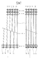
Figur 1- einen Abschnitt eines Förderbandes in einer ersten Ausführung in Aufsicht, wobei die linke Teilzeichnung eine Kurvensituation, die rechte Teilzeichnung eine Situation bei geradem Streckenverlauf wiedergibt,
- Figur 2a
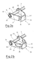
- ein Kettenglied einer Doppelkette als Detail des Förderbandes in perspektivischer Darstellung,
- Figur 2b
- ein Kettenglied einer Einzelkette als Detail des Förderbandes in perspektivischer Darstellung,
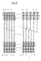
Figur 3- einen Abschnitt einer weiteren Ausführung des Förderbandes in Aufsicht, wobei die linke Teilzeichnung eine Situation bei geradem Streckenverlauf, die rechte Teilzeichnung eine Kurvensituation darstellt, und
- Figur 4
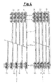
- einen Abschnitt einer dritten Ausführung des Förderbandes in Aufsicht, wobei die Teilzeichnungen Situationen analog zu denen in
Figur 1 darstellen.
- Figure 1
- a section of a conveyor belt in a first embodiment in supervision, the left-hand partial drawing representing a curve situation, the right-hand partial drawing representing a situation when the route is straight,
- Figure 2a
- a chain link of a double chain as a detail of the conveyor belt in a perspective view,
- Figure 2b
- a chain link of a single chain as a detail of the conveyor belt in a perspective view,
- Figure 3
- a section of another embodiment of the conveyor belt in supervision, the left partial drawing a situation with a straight route, the right partial drawing represents a curve situation, and
- Figure 4
- a section of a third embodiment of the conveyor belt in supervision, the partial drawings Represent situations analogous to those in Figure 1.
Wie die Figur 1 der Zeichnung zeigt, besteht das erste dargestellte Ausführungsbeispiel des Förderbandes 1 aus drei parallel verlaufenden Ketten 2, 2', 2'', von denen die Ketten 2, 2' als Doppelkette direkt nebeneinander an der einen Förderband-Längsseite verlaufen, während die dritte Kette 2'' in Abstand dazu parallel an der anderen Förderband-Längsseite verläuft. Quer zu den Ketten sind Tragstäbe 3 angeordnet, welche mit ihren Enden 31, 32 die Kettenglieder 20 der Doppelkette 2, 2' bzw. Einzelkette 2'' von innen nach außen durchdringen und dort in einem verdickten Kopf 33 enden, welcher ein Herausrutschen der Tragstäbe 3 aus den Kettengliedern 20 verhindert. Der mittlere Bereich der Tragstäbe 3 bildet die Tragfläche 30. Wie aus Figur 1 ersichtlich ist, sind die Tragstabenden 31 nur lose durch die Glieder 20 der Doppelkette 2, 2' geführt und mittels des Kopfes 33 gegen ein Herausrutschen gesichert. Die Tragstabenden 32 sind zusätzlich über einen Schweißpunkt 34 mit ihren Endköpfen 33 fest mit der Außenkante der Kettenglieder 20 der Einzelkette 2'' verbunden.As FIG. 1 of the drawing shows, the first exemplary embodiment of the
Wie aus Figur 2a und Figur 2b hervorgeht, sind die Kettenglieder 20 der Doppelkette 2, 2' und die Kettenglieder 20 der Einzelkette 2'' unterschiedlich gestaltet. Die Kettenglieder 20 der Doppelkette, dargestellt in Figur 2a, bestehen aus U-förmigen Streifen mit zwei Schenkeln 21, 22 und einem Verbindungsbogen 23. Die Schenkel 21, 22 weisen zwei Paare mit je zwei fluchtenden, kreisrunden Durchbrüchen 24, 24', 25, 25' auf, von denen das eine Paar 25, 25' sich am hinteren Schenkelende befindet und das andere Paar 24, 24' am vorderen Ende nahe dem Verbindungsbogen 23. Wie aus Figur 2a ersichtlich ist, durchdringt der Tragstab 3 mit seinem Ende 31 das Kettenglied 20 und ist an dessen Außenschenkel 21 durch seinen verdickten Kopf 33 gegen ein Herausrutschen gesichert. Auch hier ist der Außenschenkel 21 mit dem Kopf 33 durch einen Schweißpunkt 34 verbunden.As can be seen from FIG. 2a and FIG. 2b, the
Figur 2b zeigt ein Kettenglied 20 der Einzelkette 2, 2', welches gegenüber dem in Figur 2a gezeigten Kettenglied nur den Unterschied aufweist, daß die Durchbrüche des vorderen Paares 24, 24' als in Längsrichtung der Schenkel 21, 22 verlaufende Langlöcher ausgebildet sind. Wie die Figur 2b zeigt, durchdringt ein Tragstab 3 die Schenkel 21, 22 des Kettengliedes 20 mit seinem Ende 32, ist durch einen verdickten Kopf 33 gegen ein Herausrutschen gesichert und mit einem Schweißpunkt 34 fest mit der Außenseite des äußeren Schenkels 21 verbunden. Wie aus Figur 1 ersichtlich ist, durchdringen die Tragstabenden 31, 32 innerhalb der Schenkel 21, 22 aus Figur 2a und 2b die vorderen Durchbrechungen 24, 24' eines nachfolgenden Kettengliedes 20. Während die kreisrunden Durchbrechungen 24, 24', 25, 25' der Kettenglieder 20 der Doppelkette 2, 2' auch in Krümmungen einen konstanten Tragstababstand gewährleisten und so auch in einem Innenradius einen Antrieb mittels Kettenrädern ermöglichen, ermöglichen die Langlöcher 24, 24' aus Figur 2b eine einseitige Vergrößerung des Tragstababstandes und somit eine Anpassung an den größeren Außenradius in einer Kurve. Hier kann somit das Förderband in den Kurven beidseitig angetrieben werden, wobei die zum Antrieb dienenden Kettenräder wegen der unterschiedlichen Geschwindigkeiten am Außen- bzw. Innenradius unterschiedliche Durchmesser aufweisen oder mit unterschiedlichen Winkelgeschwindigkeiten angetrieben werden.Figure 2b shows a
In Figur 3 wird eine andere Ausführungsform gezeigt, welche sich von der vorhin beschriebenen dadurch unterscheidet, daß die Tragstäbe 3 in ihrem den Tragbereich 30 bildenden Bereich mit einem Drahtgittergeflecht 4 überzogen sind.Another embodiment is shown in FIG. 3, which differs from the one described above in that the
Figur 4 zeigt eine dritte Ausgestaltung des Förderbandes 1, welche sich von der in Figur 1 dargestellten dadurch unterscheidet, daß die Tragstäbe 3 auf der Oberfläche der Ketten 2, 2', 2'' aufliegen, über diese nach außen hinausreichen und mit ihren Enden 31, 32 über U-förmige Krümmungen 35 die Kettenglieder 20 von außen durchdringen. Die Schweißpunkte 34, welche die Tragstabenden 32 starr mit den Kettengliedern 20 der Einzelkette 2, 2' verbinden, sind in dieser Ausgestaltung an den Auflagepunkten der Tragstäbe 3 auf den Kettengliedern 20 angebracht, welche sie von außen durch die hinteren Rund-Löcher 25, 25' durchdringen. Dadurch wird zusätzlich zu der effektiven Antriebsmöglichkeit erreicht, daß die Tragfläche 30 wesentlich vergrößert und das maschinelle Auf- und Abschieben von Gütern erleichtert wird.FIG. 4 shows a third embodiment of the
Bei den hier beshriebenen Förderbändern bestehen die Kettenglieder 20 und die Tragstäbe 3 aus Metall, vorzugsweise korrosionsfreiem Edelstahl. Alternativ können die Kettenglieder 20 und Tragstäbe 3 der Förderbänder auch aus Kunststoff, bevorzugt mit Glasfaserverstärkung, bestehen.In the conveyor belts described here, the
Claims (10)
dadurch gekennzeichnet,
characterized,
Applications Claiming Priority (2)
| Application Number | Priority Date | Filing Date | Title |
|---|---|---|---|
| DE19904015118 DE4015118A1 (en) | 1990-05-11 | 1990-05-11 | CONVEYOR BAND |
| DE4015118 | 1990-05-11 |
Publications (1)
| Publication Number | Publication Date |
|---|---|
| EP0456145A1 true EP0456145A1 (en) | 1991-11-13 |
Family
ID=6406172
Family Applications (1)
| Application Number | Title | Priority Date | Filing Date |
|---|---|---|---|
| EP91107284A Withdrawn EP0456145A1 (en) | 1990-05-11 | 1991-05-06 | Conveyor belt |
Country Status (2)
| Country | Link |
|---|---|
| EP (1) | EP0456145A1 (en) |
| DE (1) | DE4015118A1 (en) |
Cited By (2)
| Publication number | Priority date | Publication date | Assignee | Title |
|---|---|---|---|---|
| EP0887289A1 (en) * | 1997-06-12 | 1998-12-30 | Ashworth Bros., Inc. | Conveyor belt with improved rod to link attachment |
| CN109573145A (en) * | 2019-01-24 | 2019-04-05 | 四川金仕达自动化设备有限公司 | A kind of turning chain type egg output equipment |
Families Citing this family (2)
| Publication number | Priority date | Publication date | Assignee | Title |
|---|---|---|---|---|
| DE102015105660A1 (en) | 2015-04-14 | 2016-10-20 | Bvm Brunner Gmbh & Co. Kg Verpackungsmaschinen | transport device |
| DE102015105882B4 (en) † | 2015-04-17 | 2017-06-08 | Delfortgroup Ag | Wrapping paper with high short fiber content and smoking article |
Citations (4)
| Publication number | Priority date | Publication date | Assignee | Title |
|---|---|---|---|---|
| FR1451518A (en) * | 1965-07-16 | 1966-01-07 | Charvo Sa | Improvements to non-rectilinear conveyors |
| DE2808052A1 (en) * | 1977-02-25 | 1978-11-16 | Ashworth Bros Inc | CONVEYOR SYSTEM AND CONVEYOR BELT FOR CROSSING CURVES WITH TIGHT RADIUS |
| EP0303457A1 (en) * | 1987-08-10 | 1989-02-15 | Ashworth Bros. Inc. | Conveyor belt and system with a non-collapsing inside edge |
| DE8900158U1 (en) * | 1989-01-09 | 1989-04-06 | Jonge Poerink B.V., Borne, Nl |
Family Cites Families (1)
| Publication number | Priority date | Publication date | Assignee | Title |
|---|---|---|---|---|
| US3467239A (en) * | 1967-09-05 | 1969-09-16 | Ashworth Bros Inc | Central link collapsible conveyor belt |
-
1990
- 1990-05-11 DE DE19904015118 patent/DE4015118A1/en not_active Withdrawn
-
1991
- 1991-05-06 EP EP91107284A patent/EP0456145A1/en not_active Withdrawn
Patent Citations (4)
| Publication number | Priority date | Publication date | Assignee | Title |
|---|---|---|---|---|
| FR1451518A (en) * | 1965-07-16 | 1966-01-07 | Charvo Sa | Improvements to non-rectilinear conveyors |
| DE2808052A1 (en) * | 1977-02-25 | 1978-11-16 | Ashworth Bros Inc | CONVEYOR SYSTEM AND CONVEYOR BELT FOR CROSSING CURVES WITH TIGHT RADIUS |
| EP0303457A1 (en) * | 1987-08-10 | 1989-02-15 | Ashworth Bros. Inc. | Conveyor belt and system with a non-collapsing inside edge |
| DE8900158U1 (en) * | 1989-01-09 | 1989-04-06 | Jonge Poerink B.V., Borne, Nl |
Cited By (5)
| Publication number | Priority date | Publication date | Assignee | Title |
|---|---|---|---|---|
| EP0887289A1 (en) * | 1997-06-12 | 1998-12-30 | Ashworth Bros., Inc. | Conveyor belt with improved rod to link attachment |
| US5954188A (en) * | 1997-06-12 | 1999-09-21 | Ashworth Bros., Inc. | Conveyor belt |
| US6070715A (en) * | 1997-06-12 | 2000-06-06 | Ashworth Bros., Inc. | Conveyor belt with improved rod to link attachment |
| US6195868B1 (en) | 1997-06-12 | 2001-03-06 | Ashworth Bros., Inc. | Conveyor belt with improved rod to link attachment |
| CN109573145A (en) * | 2019-01-24 | 2019-04-05 | 四川金仕达自动化设备有限公司 | A kind of turning chain type egg output equipment |
Also Published As
| Publication number | Publication date |
|---|---|
| DE4015118A1 (en) | 1991-11-14 |
Similar Documents
| Publication | Publication Date | Title |
|---|---|---|
| DE2045028C3 (en) | Apron conveyor | |
| DE2740807A1 (en) | BELT CONVEYOR | |
| DE202006020826U1 (en) | Link chain for chain conveyor and sprocket for this purpose | |
| DE1810835B2 (en) | Endless conveyor from flat wires - has wires connecting bolts located in slots for varying their spacing distance | |
| DE19724586C1 (en) | Scraper chain for chain scraper conveyors, especially for mining applications | |
| DE602004013185T2 (en) | CURVED CONVEYOR CHAIN WITH DOUBLE CROSS CONNECTORS | |
| EP1440253B1 (en) | Chain, in particular a hoist chain | |
| EP0377775A1 (en) | Conveyor belt | |
| DE2124165C3 (en) | Endless flexible cover belt for a belt conveyor | |
| EP0456145A1 (en) | Conveyor belt | |
| DE4124788A1 (en) | Arrow tooth chain for tunnel construction - has steel links with horizontal and vertical faces for smoother running of chain wheel | |
| DE705080C (en) | Schakenfoerderkette | |
| DE60127488T2 (en) | Flexible chain conveyor | |
| DE1456857A1 (en) | Trough belt conveyor | |
| DE2633475C2 (en) | ||
| DE3116365A1 (en) | Conveyor chain | |
| DE838124C (en) | Chain conveyor with a pair of link chains rotating in the middle of the conveyor trough | |
| DE2535914A1 (en) | TOW CHAIN CONVEYOR | |
| DE2152892B2 (en) | Wire conveyor belt | |
| DE2535148C3 (en) | Endless conveyor belt | |
| DE8227706U1 (en) | JAMED ROLLER CHAIN | |
| DE2243124C3 (en) | Conveyor device for transporting and cooling rolled wire | |
| DE1602242C3 (en) | Conveyor device for transporting and cooling wire | |
| AT394977B (en) | TIRE CHAIN AND METHOD FOR THEIR PRODUCTION | |
| DE945078C (en) | Slide chain for transport tracks |
Legal Events
| Date | Code | Title | Description |
|---|---|---|---|
| PUAI | Public reference made under article 153(3) epc to a published international application that has entered the european phase |
Free format text: ORIGINAL CODE: 0009012 |
|
| AK | Designated contracting states |
Kind code of ref document: A1 Designated state(s): AT BE CH DE DK ES FR GB GR IT LI NL SE |
|
| 17P | Request for examination filed |
Effective date: 19920328 |
|
| 17Q | First examination report despatched |
Effective date: 19921016 |
|
| STAA | Information on the status of an ep patent application or granted ep patent |
Free format text: STATUS: THE APPLICATION IS DEEMED TO BE WITHDRAWN |
|
| 18D | Application deemed to be withdrawn |
Effective date: 19930427 |