EP0456082A1 - Rolling contact bearing for linear motion - Google Patents
Rolling contact bearing for linear motion Download PDFInfo
- Publication number
- EP0456082A1 EP0456082A1 EP91106968A EP91106968A EP0456082A1 EP 0456082 A1 EP0456082 A1 EP 0456082A1 EP 91106968 A EP91106968 A EP 91106968A EP 91106968 A EP91106968 A EP 91106968A EP 0456082 A1 EP0456082 A1 EP 0456082A1
- Authority
- EP
- European Patent Office
- Prior art keywords
- cage
- tracks
- ball bearing
- shaft
- slot
- Prior art date
- Legal status (The legal status is an assumption and is not a legal conclusion. Google has not performed a legal analysis and makes no representation as to the accuracy of the status listed.)
- Granted
Links
Images
Classifications
-
- F—MECHANICAL ENGINEERING; LIGHTING; HEATING; WEAPONS; BLASTING
- F16—ENGINEERING ELEMENTS AND UNITS; GENERAL MEASURES FOR PRODUCING AND MAINTAINING EFFECTIVE FUNCTIONING OF MACHINES OR INSTALLATIONS; THERMAL INSULATION IN GENERAL
- F16C—SHAFTS; FLEXIBLE SHAFTS; ELEMENTS OR CRANKSHAFT MECHANISMS; ROTARY BODIES OTHER THAN GEARING ELEMENTS; BEARINGS
- F16C29/00—Bearings for parts moving only linearly
- F16C29/04—Ball or roller bearings
- F16C29/06—Ball or roller bearings in which the rolling bodies circulate partly without carrying load
- F16C29/068—Ball or roller bearings in which the rolling bodies circulate partly without carrying load with the bearing body fully encircling the guide rail or track
- F16C29/0683—Ball or roller bearings in which the rolling bodies circulate partly without carrying load with the bearing body fully encircling the guide rail or track the bearing body encircles a rail or rod of circular cross-section, i.e. the linear bearing is not suited to transmit torque
- F16C29/0685—Ball or roller bearings in which the rolling bodies circulate partly without carrying load with the bearing body fully encircling the guide rail or track the bearing body encircles a rail or rod of circular cross-section, i.e. the linear bearing is not suited to transmit torque with balls
- F16C29/069—Ball or roller bearings in which the rolling bodies circulate partly without carrying load with the bearing body fully encircling the guide rail or track the bearing body encircles a rail or rod of circular cross-section, i.e. the linear bearing is not suited to transmit torque with balls whereby discrete load bearing elements, e.g. discrete load bearing plates or discrete rods, are provided in a retainer and form the load bearing tracks
-
- F—MECHANICAL ENGINEERING; LIGHTING; HEATING; WEAPONS; BLASTING
- F16—ENGINEERING ELEMENTS AND UNITS; GENERAL MEASURES FOR PRODUCING AND MAINTAINING EFFECTIVE FUNCTIONING OF MACHINES OR INSTALLATIONS; THERMAL INSULATION IN GENERAL
- F16C—SHAFTS; FLEXIBLE SHAFTS; ELEMENTS OR CRANKSHAFT MECHANISMS; ROTARY BODIES OTHER THAN GEARING ELEMENTS; BEARINGS
- F16C43/00—Assembling bearings
- F16C43/04—Assembling rolling-contact bearings
- F16C43/06—Placing rolling bodies in cages or bearings
- F16C43/08—Placing rolling bodies in cages or bearings by deforming the cages or the races
Abstract
Ein Kugellager für Längsbewegungen besitzt einen mit seiner Innenfläche eine Welle (4) umgebenden Käfig (3). Der Käfig (3) hat axiale Führungsbahnen (8) für belastete Kugeln (9) und axiale Rückführbahnen (10) für unbelastete Kugeln (11) sowie jeweils einen Deckel (7) an jedem seiner beiden Enden. Jeder Deckel (7) hat Umlenkbahnen (15), die jeweils eine Führungsbahn (8) mit einer Rückführbahn (10) endseitig verbinden. Die Führungs- und Rückführbahnen (8, 10) haben einen entlang diesen Bahnen verlaufenden, zur Welle (4) hin offenen Schlitz (18, 20). Damit das Kugellager äußerst geräuscharm läuft, haben die Umlenkbahnen (15) ebenfalls einen zur Welle (4) hin offenen Schlitz (19), der in den Schlitz (18) der zugehörigen Führungsbahn (8) und den Schlitz (20) der zugehörigen Rückführbahn (10) einmündet. Jeder Schlitz (19) ist durch einen entlang der Umlenkbahn (15) gekrümmt verlaufenden Schulterabschnitt auf der Innenfläche des Käfigs (3) und einen parallel dazu gekrümmt verlaufenden innenseitigen Wandabschnitt des betreffenden Deckels (7) begrenzt. <IMAGE>A ball bearing for longitudinal movements has a cage (3) which surrounds a shaft (4) with its inner surface. The cage (3) has axial guide tracks (8) for loaded balls (9) and axial return tracks (10) for unloaded balls (11) and a cover (7) at each of its two ends. Each cover (7) has deflection tracks (15), each of which connects a guide track (8) to a return track (10) at the end. The guide and return paths (8, 10) have a slot (18, 20) running along these paths and open towards the shaft (4). To ensure that the ball bearing runs extremely quietly, the deflection tracks (15) also have a slot (19) that is open towards the shaft (4) and that fits into the slot (18) of the associated guide track (8) and the slot (20) of the associated return track ( 10) flows into. Each slot (19) is delimited by a shoulder section on the inner surface of the cage (3) which runs curved along the deflection path (15) and an inner wall section of the cover (7) concerned which runs parallel to it. <IMAGE>
Description
Die vorliegende Erfindung betrifft ein Kugellager für Längsbewegungen gemäß dem Oberbegriff des Anspruches 1.The present invention relates to a ball bearing for longitudinal movements according to the preamble of
Ein Kugellager der genannten Gattung ist bekannt, bei dem die Umlenkbahnen jeder Reihe von Kugeln radial nach innen zur Welle hin durch eine Anlauframpe des Käfigs geschlossen sind (DE-PS 27 25 355). Im Betrieb des bekannten Kugellagers bewegen sich die Kugeln längs den Führungs- und Rückführbahnen und werden an dieser Anlauframpe von der Welle radial abgehoben. Die entsprechenden Anlaufbewegungen und radialen Verlagerungen der Kugeln rufen aber im Kugellager Stoßkräfte hervor, die ein unerwünschtes Laufgeräusch des Kugellagers zur Folge haben können.A ball bearing of the type mentioned is known, in which the deflection paths of each row of balls are closed radially inwards towards the shaft by a ramp of the cage (DE-PS 27 25 355). In the operation of the known ball bearing, the balls move along the guide and return paths and are lifted radially from the shaft on this starting ramp. However, the corresponding start-up movements and radial displacements of the balls cause shock forces in the ball bearing, which can result in undesired running noise from the ball bearing.
Die Anlauframpen des Kugellagers müssen übrigens mit komplizierten Werkzeugen in den Käfig und in die zugehörigen Deckel eingearbeitet werden. Schließlich sind die Anlauframpen des bekannten Kugellagers aber auch wegen ihrer Dünnwandigkeit verhältnismäßig empfindlich.Incidentally, the ramp of the ball bearing must be worked into the cage and the associated cover using complicated tools. Finally, the starting ramps of the known ball bearing are also relatively sensitive because of their thin walls.
Der im Anspruch 1 gekennzeichneten Erfindung liegt demgegenüber die Aufgabe zugrunde, ein Kugellager für Längsbewegungen der genannten Gattung zu schaffen, welches äußerst geräuscharm läuft, robust gebaut ist und außerdem besonders wirtschaftlich hergestellt werden kann.The invention characterized in
Mit dem Kugellager für Längsbewegungen der Erfindung wird erreicht, daß die Kugeln jeder Reihe, von der Führungsbahn oder von der Rückführbahn kommend, in die Umlenkbahn des betreffenden Deckels glatt und geräuschlos einlaufen. Ebenso werden die Kugeln jeder Reihe ohne abrupte radiale Verlagerung von der betreffenden Umlenkbahn zurück in die anschließende Führungs- oder Rückführbahn geleitet. Auf diese Weise erfahren die Kugeln bei ihrer Bewegung im Kugellager überhaupt keine Anlaufstöße. Das Kugellager der Erfindung hat dementsprechend eine besonders große Laufruhe und kann eine vorteilhaft kleine radiale Bauhöhe aufweisen.With the ball bearing for longitudinal movements of the invention it is achieved that the balls of each row, coming from the guideway or from the return path, run smoothly and noiselessly into the deflection path of the cover in question. Likewise, the balls of each row are guided from the relevant deflection path back into the subsequent guiding or return path without an abrupt radial displacement. In this way, the balls do not experience any shock during their movement in the ball bearing. The ball bearing of the invention accordingly has a particularly great smoothness and can have an advantageously small radial height.
Die gekrümmt verlaufenden Schulterabschnitte in der Bohrung des Käfigs und die entsprechend gekrümmt verlaufenden Wandabschnitte des betreffenden Deckels lassen sich beim erfindungsgemäßen Kugellager durch Axialwerkzeuge wirtschaftlich einarbeiten. Dabei können der Käfig als auch die beiden zugehörigen Deckel eine Form erhalten, die eine relativ stoßfeste und robuste Ausbildung des Kugellagers zur Folge hat.The curved shoulder sections in the bore of the cage and the corresponding curved wall sections of the cover in question can be economically incorporated into the ball bearing according to the invention by axial tools. The cage and the two associated lids can be given a shape that results in a relatively impact-resistant and robust design of the ball bearing.
Vorteilhafte Weiterbildungen der Erfindung sind in den Unteransprüchen gekennzeichnet.Advantageous developments of the invention are characterized in the subclaims.
Die Weiterbildung nach Anspruch 2 hat zur Folge, daß die unbelasteten Kugeln jeder endlosen Reihe durch den Schlitz der Rückführ- und Umlenkbahn bis zur Mantelfläche der Welle vorragen und auf dieser geführt werden.The development according to
Mit der Weiterbildung nach Anspruch 3 wird erreicht, daß die Kugeln jeder Reihe von radial inneren Schlitzrändern der Schlitze festgehalten werden, so daß diese bei ausgebauter Welle aus den Kugellager nicht herausfallen können.With the development according to
Die Weiterbildungen nach Anspruch 4 bis 9 weisen auf Ausgestaltungen des Käfigs und der beiden Deckel hin, die eine besonders wirtschaftliche Fertigung des Kugellagers ermöglichen.The developments according to
Schließlich wird mit der Weiterbildung nach Anspruch 10 noch der Vorteil erzielt, daß sowohl die Führungsbahnen und Rückführbahnen des Käfigs als auch die Umlenkbahnen der beiden Deckel mit Axialschiebern in einer Gießform eingeformt werden können, so daß sich eine wirtschafliche Massenfertigung des Käfigs und der Deckel ergibt.Finally, with the development according to
Das erfindungsgemäße Kugellager für Längsbewegungen wird in der nachfolgenden Beschreibung zweier Ausführungsbeispiele anhand der zugehörigen Zeichnungen näher beschrieben. Es zeigen:
- Fig. 1
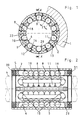
- den Querschnitt durch ein in der Bohrung eines Gehäuses eingebautes erfindungsgemäßes Kugellager für Längsbewegungen,
- Fig. 2
- den Längsschnitt entlang A - A in
Figur 1, jedoch ohne Gehäuse, - Fig. 3
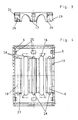
- den Längsschnitt durch einen der beiden Deckel des in
Figur 1 gezeigten Kugellagers im ausgebauten Zustand, - Fig. 4
- den Längsschnitt durch den Käfig des in
Figur 1 gezeigten Kugellagers im ausgebauten Zustand, - Fig. 5
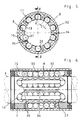
- den Querschnitt durch ein abgeändertes Kugellager für Längsbewegungen und
- Fig. 6
- den Längsschnitt entlang B - B in
Figur 5.
- Fig. 1
- the cross section through a ball bearing according to the invention for longitudinal movements installed in the bore of a housing,
- Fig. 2
- 2 shows the longitudinal section along A - A in FIG. 1, but without the housing,
- Fig. 3
- 2 shows the longitudinal section through one of the two covers of the ball bearing shown in FIG. 1 in the disassembled state,
- Fig. 4
- 2 shows the longitudinal section through the cage of the ball bearing shown in FIG. 1 in the removed state,
- Fig. 5
- the cross section through a modified ball bearing for longitudinal movements and
- Fig. 6
- the longitudinal section along B - B in Figure 5.
Mit 1 ist in Figur 1 ein Gehäuse bezeichnet, in dessen zylindrischer Bohrung 2 ein Käfig eines seitensymmetrischen Kugellagers für Längsbewegungen eingebaut ist. Der Käfig 3 ist hülsenförmig ausgebildet, so daß dieser mit einer Innenfläche eine zylindrische Welle 4 - siehe strichpunktierte Darstellungen in Figur 1 und 2 - vollständig umgibt.1 in FIG. 1 denotes a housing, in the
An jedem seiner beiden Enden ist am Käfig ein ringförmiger Deckel 7 befestigt, der auf einer zylindrischen Bohrungsfläche 6 jeweils eines Endabschnittes 5 des Käfigs 3 sitzt (Figur 2).At each of its two ends, an
Der Käfig 3 hat axiale Führungsbahnen 8 für belastete Kugeln 9 und axiale Rückführbahnen 10 für unbelastete Kugeln 11. Der Käfig 3 und seine beiden Deckel 7 bestehen aus einem Elastomer-Gießwerkstoff, sie sind jeweils im Spritzgießverfahren in einer Gießform (nicht gezeigt) hergestellt. Die Gießform des Käfigs kann in an sich bekannter Weise Axialschieber zum Einformen der Führungsbahnen 8 und Rückführbahnen 10 des Käfigs 3 besitzen.The
Jeweils eine Führungsbahn 8 und eine Rückführbahn 10 sind abwechselnd am Umfang des Käfigs 3 angeordnet. Radial über jeder Führungsbahn 8 ist im Käfig ein Laufbahnelement 12 aus Stahl eingebaut. Jedes Laufbahnelement 12 ist in einer radial durchgehenden Öffnung 13 des Käfigs 3 unverlierbar eingeschnappt, es hat eine in der Bohrung des Gehäuses 1 radial abgestützte Außenseite und eine mit einer längsverlaufenden rillenförmigen Laufbahn 14 für die belasteten Kugeln 9 versehene Innenseite.One
Bei axialer Hin- und Herbewegung der Welle 4 rollen die Kugeln 9 zwischen der Laufbahn 14 des betreffenden Laufbahnelementes 12 und einer zylindrischen Mantelfläche der Welle 4 und übertragen dabei eine radiale Belastung von der Welle 4 über das Laufbahnelement 12 zur Bohrung 2 des Gehäuses 1.When the
Die beiden Deckel 7 besitzen auf ihrer Innenseite am Umfang verteilt angeordnete, halbkreisförmig verlaufende Umlenkbahnen 15. Jede Umlenkbahn 15 verbindet jeweils das Ende einer Führungsbahn 8 mit dem Ende einer benachbarten Rückführbahn 10. Dabei ist jede Umlenkbahn 15 durch einen entsprechend halbförmig gekrümmt verlaufenden Schulterabschnitt 16 auf der Innenfläche des Käfigs 3 und einen diesem gegenüberstehenden, parallel dazu gekrümmt verlaufenden, innenseitigen Wandabschnitt 17 des Deckel 7 begrenzt.The two
Jeweils eine Führungsbahn 8, eine Rückführbahn 10 und zwei einander axial gegenüberliegend angeordnete endseitige Umlenkbahnen 15 bilden eine in sich geschlossene Bahn, in der eine endlose Reihe von Kugeln 9, 11 eingebaut ist.In each case a
Jede geschlossene Bahn des Kugellagers hat einen entlang dieser verlaufenden, zur Welle 4 hin offenen Schlitz, der aus einem axial verlaufenden Schlitz 18 der Führungsbahn 8, einem halbkreisförmig verlaufenden Schlitz 19 der beiden Umlenkbahnen 15 und einem axial verlaufenden Schlitz 20 der Rückführbahn 10 zusammengesetzt ist. Dabei mündet der Schlitz 19 jeder Umlenkbahn 15 an seinen Enden in den Schlitz 8 der anschließenden Führungsbahn 8 bzw. in den Schlitz 20 der anschließenden Rückführbahn 10.Each closed track of the ball bearing has a slot running along it, open towards the
Die radial innere Schlitzbreite 21 des Schlitzes 19 der Umlenkbahnen 15 ist genauso groß wie die innere Schlitzbreite der Rückführbahnen 10, sie ist genügend groß, so daß die unbelasteten Kugeln 11 bis zur Welle 4 hin radial nach innen aus dem Schlitz 19 und 20 herausragen und somit auf der Welle 4 radial geführt werden.The radially
Die Schlitzbreite 21 ist übrigens etwas kleiner als der Durchmesser der Kugeln 11. Ebenso ist die radial innere Schlitzbreite des Schlitzes 18 jeder Führungsbahn 8 etwas kleiner als der Durchmesser der Kugeln 9. Auf diese Weise können die Kugeln 9, 11 aus dem Kugellager radial nach innen nicht herausfallen, wenn die Welle 4 aus dem Kugellager herausgezogen und entfernt ist.The
Die Umlenkbahnen 15 der beiden Deckel 7 haben durch den Schulterabschnitt 16 und den Wandabschnitt 17 gebildete seitliche Führungswände, welche eine die Kugeln 11 zum Teil umfassende, im wesentlichen kreisabschnittförmige Querschnittskontur besitzen. Ebenso haben die axial verlaufenden Führungs- und Rückführungsbahnen 8 bzw. 10 seitliche Führungswände, welche eine die Kugeln 9 bzw. 11 zum Teil umfassende, im wesentlichen kreisabschnittförmige Querschnittskontur aufweisen.The
Dabei haben die Führungs- und Rückführbahnen 8, 10 und die Umlenkbahnen 15 Querschnittmitten, die auf einem gemeinsamen, zur Achse der Welle 4 konzentrischen Zylinder 22 liegend angeordnet sind. Die Bohrungsfläche 6 jedes Endabschnittes 5 des Käfigs 3 deckt die Umlenkbahnen 15 des betreffenden Deckels 7 radial von außen ab.The guide and return
Jeder Deckel 7 hat eine auf der Bohrungsfläche 6 sitzende Mantelfläche 23, die mit am Umfang angeordneten, über die Mantelfläche 23 radial nach außen vorragenden Haltenasen 24 versehen ist. Die Haltenasen 24 sind in entsprechende, radial durchgehende Vertiefungen 25 der Bohrungsfläche 6 des Käfigs 3 einschnappend und formschlüssig eingreifend angeordnet (Figur 3 und 4).Each
Außerdem hat jeder Deckel 7 axial nach innen weisende ebene Stirnflächenabschnitte 26. Jeweils ein Stirnflächenabschnitt 26 ist zwischen zwei am Umfang benachbarten Umlenkbahnen 15 am Deckel 7 angeformt. Sämtliche Stirnflächenabschnitte 26 des Deckels 7 sind auf jeweils einem diesem gegenüberliegenden ebenen Stützflächenabschnitt 27 des Käflgs 3 fest anliegend angeordnet.In addition, each
Im vorliegenden Fall hat jeder Stützflächenabschnitt 27 einen axialen zapfenförmigen Vorsprung 28, der in einer Rundlochvertiefung 29 des zugehörigen Stirnflächenabschnitts 26 eingreift (Figur 3 und 4).In the present case, each
Bei dem in Figur 2 dargestellten Kugellager ist am linken Ende des Käfigs 3 noch ein Dichtring 30 eingesetzt, der mit der Mantelfläche der Welle 4 einen engen Dichtspalt bildet. Am rechten Ende hat der Käfig 3 einen Dichtring 31, dessen Dichtlippen auf der Mantelfläche der Welle 4 in Längsrichtung gleiten.In the ball bearing shown in Figure 2, a sealing
In Figur 5 und 6 ist ein abgeändertes Kugellager für Längsbewegungen dargestellt, welches ähnlich wie das vorhergehend beschriebene Kugellager gebaut ist, denn dieses besitzt ebenfalls axiale Führungs- und Rückführbahnen 8 bzw. 10 eines Käfigs 3 und halbkreisförmig verlaufende Umlenkbahnen 15 zweier endseitiger Deckel 7. Die Bahnen 8, 10 und 15 haben auch einen zur Welle 4 hin offenen Schlitz 18, 19 bzw. 20.In Figures 5 and 6, a modified ball bearing for longitudinal movements is shown, which is constructed similarly to the ball bearing described above, because this also has axial guide and return
Beim abgeänderten Kugellager ist jedoch jedes Laufbahnelement durch eine keramische oder metallische Schicht 32 auf einem radial äußeren Wand ungsabschnitt 33, der in Querschnittkreis abschnittförmigen Führungsbahn 8 des Käfigs 3 hergestellt. Zum Aufbringen der Schicht 32 kann ein Spritz- oder Aufdampf-Verfahren (Plasmastrahlverfahren) angewendet werden.In the modified ball bearing, however, each raceway element is formed by a ceramic or
Der Käfig 3 hat zwei endseitige Deckel 7, deren ebene Stirnflächenabschnitte auf jeweils einem diesem gegenüberliegenden ebenen Stützflächenabschnitt 27 des Käfigs 3, z. B. durch Kleben oder Ultraschallschweißen, unlösbar befestigt sind.The
In seiner Bohrung besitzt der Käfig 3 im Gießverfahren mit Axialschiebern (nicht gezeight) eingeformte radiale Einschnitte 34, die durch jeweils zwei einander axial gegenüberstehende Stützflächenabschnitte 27 des Käfigs 3 hindurchgehen. Jeder Einschnitt 34 ist radial nach innen, zur Welle 4 hin, offen und radial nach außen geschlossen. An einem oder an beiden Enden mindestens eines Einschnittes 34 greift ein höchenstens bis zum Stirnflächenabschnitt des axial gegenüberliegenden Deckels 7 reichender axialer Vorsprung 35 eines Stützflächenabschnittes 27 des betreffenden Deckels 7 in den Einschnitt 34 formschlüssig ein.In its bore, the
Jeder Einschnitt 34 verläuft in unmittelbarer Nähe einer der Rückführbahnen 10 des Käfigs 3, so daß zwischen der Rückführbahn 10 und den Einschnitt 34 ein dünnwandiger, biegeelastischer Käfigabschnitt 36 gebildet ist.Each
Beim Einfüllen der Kugeln 9, 11 in den mit oder ohne Deckel 7 versehenen Käfig 3 kann jede Kugel in die Bohrung des Käfigs 3 eingeführt, von dort radial nach außen gedrückt und in die Rückführbahn 10 eingeschnappt werden (siehe Kugel 37 in Figur 5). Dabei wird der Käfigabschnitt 36 in Umfangsrichtung etwas elastisch beiseite gebogen, so daß sich die innere Breite 21 des Schlitzes 20 kurzzeitig vergrößert.When the
Im Rahmen des Erfindungsgedankens lassen sich die oben beschriebenen Ausführungsbeispiele abändern. So können z. B. unterschiedlich große Kugeln je Reihe im Kugellager für Längsbewegungen eingebaut sein. In diesem Fall können die belasteten Kugeln der Reihe mit den größeren Kugeln auch in einer längsverlaufenden Laufbahnrille der ansonst zylindrischen Welle laufen und somit ein Drehmoment zwischen der Welle und dem betreffenden Laufbahnelement des Käfigs übertragen. Die zugehörige Rückführbahn verläuft dann in einer gegenüber der Führungsbahn etwas radial nach außen versetzten Lage, so daß die in den beiden Umlenkbahnen und in der anschließenden Rückführbahn sich entlang bewegenden unbelasteten größeren Kugeln auf einem zylindrischen Abschnitt der Welle geführt werden.The exemplary embodiments described above can be modified within the scope of the inventive concept. So z. B. different sized balls per row in the ball bearing for longitudinal movements. In this case, the loaded balls of the row with the larger balls can also run in a longitudinal raceway groove of the otherwise cylindrical shaft and thus transmit a torque between the shaft and the relevant raceway element of the cage. The associated return path then runs in a position which is somewhat radially outward with respect to the guide path, so that the larger balls which move in the two deflection paths and in the subsequent return path are guided on a cylindrical section of the shaft.
Auch braucht der Käfig nicht als am Umfang geschlossene Hülse ausgebildet zu sein. Vielmehr können Käfig und zugehörige Deckel auch einen gemeinsamen, in Längsrichtung durchgehenden Schlitz aufweisen, so daß der Käfig mit seiner Innenfläche die Welle nur zum Teil umgibt. In diesen Schlitz können dann Stützelemente eines Fundamentes oder dergleichen eingreifen, welche mit der Welle kraftschlüssig verbunden sind und diese auf dem Fundament abstützen.The cage also need not be designed as a sleeve which is closed on the circumference. Rather, the cage and the associated cover can also have a common slot extending in the longitudinal direction, so that the inner surface of the cage only partially surrounds the shaft. Support elements of a foundation or the like can then engage in this slot, which are non-positively connected to the shaft and support it on the foundation.
Claims (10)
daß die Umlenkbahnen (15) der beiden Deckel (7) einen zur Welle (4) hin offenen, in den Schlitz (18) der zugehörigen Führungsbahn (8) und in den Schlitz (20) der zugehörigen Rückführbahn (10) einmündenden Schlitz (19) besitzen, der durch jeweils einen entlang der Umlenkbahn (15) gekrümmt verlaufenden Schulterabschnitt (16) auf der Innenfläche des Käfigs (3) und einen parallel dazu gekrümmt verlaufenden innenseitigen Wandabschnitt (17) des betreffenden Deckels (7) begrenzt ist.Ball bearing for longitudinal movements along a shaft consisting of a cage which can be fixed in a bore of a housing and has an inner surface at least partially surrounding the shaft with axial guideways for loaded balls rolling between a radially outer raceway element and the shaft and axial return paths for unloaded balls, with a Lids attached to each of its two ends, each with a guide track with deflection tracks connecting a return track at the end and with balls guided in an endless row in these tracks, the guide tracks and the return tracks having a slot running along these tracks and opening towards the shaft, characterized in that
that the deflection tracks (15) of the two covers (7) have a slot (19.) that opens towards the shaft (4), into the slot (18) of the associated guide track (8) and into the slot (20) of the associated return track (10) ), which is delimited by a shoulder section (16) which runs curved along the deflection path (15) on the inner surface of the cage (3) and an inner wall section (17) of the cover (7) concerned which runs parallel to it.
dadurch gekennzeichnet,
daß zum Führen der unbelasteten Kugeln (11) jeder Reihe auf der Welle (4) sowohl der Schlitz (19) der Umlenkbahnen (15) jedes Deckels (7) als auch der Schlitz (20) der Rückführbahnen (10) des Käfigs (3) eine ein Herausragen der Kugeln (9, 11) bis zur Welle (4) zulassende radial innere Schlitzbreite (21) aufweisen.Ball bearing according to claim 1,
characterized,
that for guiding the unloaded balls (11) of each row on the shaft (4) both the slot (19) of the deflection tracks (15) of each cover (7) and the slot (20) of the return tracks (10) of the cage (3) have a radially inner slot width (21) which allows the balls (9, 11) to protrude up to the shaft (4).
dadurch gekennzeichnet,
daß die radial innere Schlitzbreite (21) der Führungs- und Rückführbahnen (8, 10) des Käfigs (3) und der Umlenkbahnen (15) der beiden Deckel (7) etwas kleiner als der Durchmesser der Kugeln (9 bzw. 11) ist.Ball bearing according to claim 2,
characterized,
that the radially inner slot width (21) of the guide and return paths (8, 10) of the cage (3) and the deflection paths (15) of the two covers (7) is slightly smaller than the diameter of the balls (9 and 11).
dadurch gekennzeichnet,
daß die Führungsbahnen (8) und Rückführbahnen (10) des Käfigs (3) und die Umlenkbahnen (15) der beiden Deckel (7) seitliche Führungswände, welche eine die Kugeln (9 bzw. 11) zum Teil umfassende, im wesentlichen kreisabschnittförmige Querschnittskontur besitzen, aufweisen.Ball bearing according to one of the preceding claims,
characterized,
that the guide tracks (8) and return tracks (10) of the cage (3) and the deflecting tracks (15) of the two covers (7) have lateral guide walls which have a cross-sectional contour which is substantially circular in section and which partially surrounds the balls (9 and 11) , exhibit.
dadurch gekennzeichnet,
daß die Führungsbahnen (8) und Rückführbahnen (10) des Käfigs (3) und die Umlenkbahnen (15) der beiden Deckel (7) Querschnittmitten aufweisen, die auf einem gemeinsamen, zur Achse der Welle (4) konzentrischen Zylinder (22) liegend angeordnet sind.Ball bearing for longitudinal movements along a cylindrical shaft according to one of the preceding claims,
characterized,
that the guide tracks (8) and return tracks (10) of the cage (3) and the deflection tracks (15) of the two covers (7) have cross-sectional centers which are arranged lying on a common cylinder (22) concentric with the axis of the shaft (4) are.
dadurch gekennzeichnet,
daß der Käfig (3) an seinen beiden Enden jeweils einen Endabschnitt (23) mit einer die Umlenkbahnen (15) des betreffenden Deckels (7) radial von außen abdeckenden Bohrungsfläche (6) aufweist.Ball bearing according to one of the preceding claims,
characterized,
that the cage (3) has at its two ends an end section (23) with a deflection path (15) of the cover (7) in question radially from the outside covering bore surface (6).
dadurch gekennzeichnet,
daß jeder Deckel (7) eine Mantelfläche (23) mit am Umfang angeordneten, radial nach außen vorragenden Haltenasen (24) aufweist, welche in entsprechende radiale Vertiefungen (25) in der Bohrungsfläche (6) des Endabschnittes (5) des Käfigs (3) einschnappend angeordnet sind.Ball bearing according to claim 5,
characterized,
that each cover (7) has a circumferential surface (23) with radially outwardly projecting retaining lugs (24) arranged in the circumference, which in corresponding radial recesses (25) in the bore surface (6) of the end portion (5) of the cage (3) are arranged snapping.
dadurch gekennzeichnet,
daß jeder Deckel (7) zwischen zwei am Umfang benachbarten Umlenkbahnen (15) jeweils einen axial nach innen weisenden Stirnflächenabschnitt (26) aufweist, der auf einem diesem gegenüberliegenden Stützflächenabschnitt (27) des Käfigs (3) fest anliegend angeordnet ist.Ball bearing according to one of the preceding claims,
characterized,
that each cover (7) between two circumferentially adjacent deflection tracks (15) each has an axially inwardly facing end face section (26) which is arranged on a support face section (27) of the cage (3) opposite this.
dadurch gekennzeichnet,
daß jeder Stützflächenabschnitt (27) des Käfigs (3) einen axialen Vorsprung (28) besitzt, der in eine Vertiefung (29) des zugehörigen Stirnflächenabschnitts (26) des Deckels (7) formschlüssig eingreifend angeordnet ist.Ball bearing according to claim 8,
characterized,
that each support surface section (27) of the cage (3) has an axial projection (28) which is arranged in a recess (29) of the associated end surface section (26) of the cover (7) in a form-fitting manner.
dadurch gekennzeichnet,
daß der Käfig (3) und/oder die beiden Deckel (7) aus einem Gießwerkstoff im Gießverfahren hergestellt sind (ist).Ball bearing according to one of the preceding claims,
characterized,
that the cage (3) and / or the two lids (7) are (is) made of a casting material in the casting process.
Applications Claiming Priority (2)
| Application Number | Priority Date | Filing Date | Title |
|---|---|---|---|
| DE4015124A DE4015124A1 (en) | 1990-05-11 | 1990-05-11 | BALL BEARING FOR LONGITUDINAL MOVEMENTS |
| DE4015124 | 1990-05-11 |
Publications (2)
| Publication Number | Publication Date |
|---|---|
| EP0456082A1 true EP0456082A1 (en) | 1991-11-13 |
| EP0456082B1 EP0456082B1 (en) | 1993-12-22 |
Family
ID=6406175
Family Applications (1)
| Application Number | Title | Priority Date | Filing Date |
|---|---|---|---|
| EP91106968A Expired - Lifetime EP0456082B1 (en) | 1990-05-11 | 1991-04-30 | Rolling contact bearing for linear motion |
Country Status (4)
| Country | Link |
|---|---|
| US (1) | US5145260A (en) |
| EP (1) | EP0456082B1 (en) |
| JP (1) | JP2859463B2 (en) |
| DE (2) | DE4015124A1 (en) |
Cited By (5)
| Publication number | Priority date | Publication date | Assignee | Title |
|---|---|---|---|---|
| FR2759432A1 (en) * | 1997-02-07 | 1998-08-14 | Skf Linearsysteme Gmbh | BALL BEARING FOR LONGITUDINAL MOVEMENTS AND MANUFACTURING METHOD THEREOF |
| EP1970582A2 (en) | 2007-03-16 | 2008-09-17 | Ab Skf | Sealing element in a linear bearing |
| EP1970583A2 (en) | 2007-03-16 | 2008-09-17 | Ab Skf | Linear roller bearing |
| EP1970581A3 (en) * | 2007-03-16 | 2012-04-25 | Ab Skf | Linear roller bearing |
| EP1970584A3 (en) * | 2007-03-16 | 2012-04-25 | Ab Skf | Linear roller bearing |
Families Citing this family (12)
| Publication number | Priority date | Publication date | Assignee | Title |
|---|---|---|---|---|
| US5221145A (en) * | 1992-01-17 | 1993-06-22 | Rmb Roulements Miniatures | Linear bearing |
| DE4223499C2 (en) * | 1992-07-17 | 2002-02-21 | Schaeffler Waelzlager Ohg | Rolling bearings for straight movement |
| US5558442A (en) * | 1993-07-20 | 1996-09-24 | Thomson Industries, Inc. | Linear motion bearing assembly |
| DE19704633C1 (en) * | 1997-02-07 | 1998-07-09 | Skf Linearsysteme Gmbh | Ball bearings for longitudinal movements |
| DE19704630C2 (en) * | 1997-02-07 | 1999-08-12 | Skf Linearsysteme Gmbh | Radial seal |
| DE19741626B4 (en) * | 1997-09-20 | 2008-03-27 | Skf Linearsysteme Gmbh | Ball bearing for longitudinal movements |
| JP2003004040A (en) * | 2001-06-19 | 2003-01-08 | Thk Co Ltd | Rolling guide apparatus |
| DE102005054516B3 (en) * | 2005-11-16 | 2007-03-22 | Aktiebolaget Skf | Linear bearing for a rolling body has bearing parts sliding relative to each other in a translational direction with grooves each to receive a slide-way plate with slide-ways for rolling bodies |
| EP2603707B1 (en) * | 2010-08-11 | 2016-10-05 | Thomson Industries, Inc. | Clam shell linear motion bearing assembly |
| DE102011017757B4 (en) * | 2011-04-29 | 2014-11-27 | Aktiebolaget Skf | Concept for sealing a linear guide |
| JP5695248B2 (en) * | 2013-04-10 | 2015-04-01 | Thk株式会社 | Exercise guidance device |
| JP7319023B2 (en) * | 2019-03-07 | 2023-08-01 | Thk株式会社 | ball spline |
Citations (3)
| Publication number | Priority date | Publication date | Assignee | Title |
|---|---|---|---|---|
| CH519118A (en) * | 1970-01-22 | 1972-02-15 | Roulements Miniatures S A | Ball bearing for mounting longitudinally movable shafts |
| FR2384155A2 (en) * | 1977-03-18 | 1978-10-13 | Skf Kugellagerfabriken Gmbh | BALL SOCKET |
| DE2725355C2 (en) * | 1977-06-04 | 1984-04-12 | Skf Kugellagerfabriken Gmbh, 8720 Schweinfurt | Linear Bushing |
Family Cites Families (3)
| Publication number | Priority date | Publication date | Assignee | Title |
|---|---|---|---|---|
| DE3207516A1 (en) * | 1982-03-03 | 1983-09-08 | Skf Kugellagerfabriken Gmbh | ROLLER BEARING FOR LONGITUDINAL MOVEMENTS |
| US4469380A (en) * | 1982-05-19 | 1984-09-04 | The Torrington Company | Linear movement anti-friction bearing |
| DE3937781A1 (en) * | 1989-04-08 | 1990-10-11 | Werner Dipl Ing Jacob | BALL REVERSE UNIT FOR A LINEAR BALL GUIDE |
-
1990
- 1990-05-11 DE DE4015124A patent/DE4015124A1/en not_active Withdrawn
-
1991
- 1991-04-30 DE DE91106968T patent/DE59100745D1/en not_active Expired - Lifetime
- 1991-04-30 EP EP91106968A patent/EP0456082B1/en not_active Expired - Lifetime
- 1991-05-09 JP JP3132191A patent/JP2859463B2/en not_active Expired - Lifetime
- 1991-05-10 US US07/698,662 patent/US5145260A/en not_active Expired - Lifetime
Patent Citations (3)
| Publication number | Priority date | Publication date | Assignee | Title |
|---|---|---|---|---|
| CH519118A (en) * | 1970-01-22 | 1972-02-15 | Roulements Miniatures S A | Ball bearing for mounting longitudinally movable shafts |
| FR2384155A2 (en) * | 1977-03-18 | 1978-10-13 | Skf Kugellagerfabriken Gmbh | BALL SOCKET |
| DE2725355C2 (en) * | 1977-06-04 | 1984-04-12 | Skf Kugellagerfabriken Gmbh, 8720 Schweinfurt | Linear Bushing |
Cited By (7)
| Publication number | Priority date | Publication date | Assignee | Title |
|---|---|---|---|---|
| FR2759432A1 (en) * | 1997-02-07 | 1998-08-14 | Skf Linearsysteme Gmbh | BALL BEARING FOR LONGITUDINAL MOVEMENTS AND MANUFACTURING METHOD THEREOF |
| EP1970582A2 (en) | 2007-03-16 | 2008-09-17 | Ab Skf | Sealing element in a linear bearing |
| EP1970583A2 (en) | 2007-03-16 | 2008-09-17 | Ab Skf | Linear roller bearing |
| EP1970582A3 (en) * | 2007-03-16 | 2012-04-25 | Ab Skf | Sealing element in a linear bearing |
| EP1970581A3 (en) * | 2007-03-16 | 2012-04-25 | Ab Skf | Linear roller bearing |
| EP1970584A3 (en) * | 2007-03-16 | 2012-04-25 | Ab Skf | Linear roller bearing |
| EP1970583A3 (en) * | 2007-03-16 | 2012-08-22 | Ab Skf | Linear roller bearing |
Also Published As
| Publication number | Publication date |
|---|---|
| JP2859463B2 (en) | 1999-02-17 |
| DE4015124A1 (en) | 1991-11-14 |
| DE59100745D1 (en) | 1994-02-03 |
| US5145260A (en) | 1992-09-08 |
| JPH04228917A (en) | 1992-08-18 |
| EP0456082B1 (en) | 1993-12-22 |
Similar Documents
| Publication | Publication Date | Title |
|---|---|---|
| EP0456082B1 (en) | Rolling contact bearing for linear motion | |
| DE3841629C2 (en) | Roller bearings | |
| EP1200749B1 (en) | Linear roller bearing | |
| DE2711882C2 (en) | Linear Bushing | |
| EP0489235A1 (en) | Split cage for rolling elements | |
| DE2909508A1 (en) | ROLLER BEARING FOR LONGITUDINAL MOVEMENTS | |
| DE2649245A1 (en) | BALL BEARINGS FOR LONGITUDINAL MOVEMENTS | |
| DE7911040U1 (en) | ROLLER BEARING FOR LONGITUDINAL MOVEMENTS | |
| EP0210650B1 (en) | Electromagnet | |
| DE3512013C2 (en) | ||
| DE3041804A1 (en) | ROLLER BEARING FOR THE LENGTH GUIDE OF A SHAFT OR THE LIKE | |
| DE1575608B2 (en) | Rolling bearings for longitudinal movements | |
| DE3142047A1 (en) | DEVICE FOR DIE CASTING A ROLLER BEARING CAGE | |
| DE3326601A1 (en) | BALL BEARING FOR LONGITUDINAL MOVEMENTS | |
| DE2631808C2 (en) | Linear bushing for longitudinal guides | |
| DE2019506B2 (en) | Ball bearing axially movable along shaft - has cage sleeve in halves divided along transverse line and contained in support sleeve with end gaps | |
| EP2789867B1 (en) | Ball guiding channel of a linear guide with ball bearings | |
| DE3607634C2 (en) | ||
| DE2832744C2 (en) | Linear Bushing | |
| DE19704632C1 (en) | Ball-bearing for movement along shaft | |
| DE3533403A1 (en) | Rolling bearing for longitudinal motion | |
| DE3902937C2 (en) | Swivel bearing | |
| DE2834209A1 (en) | Ball bearing supporting longitudinal movements - has recirculating ball tracks in cage and extra track for torque transmission | |
| DE3216440A1 (en) | BALL BEARING FOR LENGTH AND TURNING MOTIONS | |
| DE10225747A1 (en) | Assembly of track ring on generated surface of outer race of rolling bearing has shoulder formed in one piece on inner side of track ring in area outside outer bearing race and with inside radius smaller than outside radius of outer race |
Legal Events
| Date | Code | Title | Description |
|---|---|---|---|
| PUAI | Public reference made under article 153(3) epc to a published international application that has entered the european phase |
Free format text: ORIGINAL CODE: 0009012 |
|
| AK | Designated contracting states |
Kind code of ref document: A1 Designated state(s): CH DE FR GB IT LI SE |
|
| 17P | Request for examination filed |
Effective date: 19911125 |
|
| 17Q | First examination report despatched |
Effective date: 19930512 |
|
| GRAA | (expected) grant |
Free format text: ORIGINAL CODE: 0009210 |
|
| AK | Designated contracting states |
Kind code of ref document: B1 Designated state(s): CH DE FR GB IT LI SE |
|
| PG25 | Lapsed in a contracting state [announced via postgrant information from national office to epo] |
Ref country code: IT Free format text: LAPSE BECAUSE OF FAILURE TO SUBMIT A TRANSLATION OF THE DESCRIPTION OR TO PAY THE FEE WITHIN THE PRE;WARNING: LAPSES OF ITALIAN PATENTS WITH EFFECTIVE DATE BEFORE 2007 MAY HAVE OCCURRED AT ANY TIME BEFORE 2007. THE CORRECT EFFECTIVE DATE MAY BE DIFFERENT FROM THE ONE RECORDED.SCRIBED TIME-LIMIT Effective date: 19931222 Ref country code: SE Effective date: 19931222 |
|
| REF | Corresponds to: |
Ref document number: 59100745 Country of ref document: DE Date of ref document: 19940203 |
|
| PGFP | Annual fee paid to national office [announced via postgrant information from national office to epo] |
Ref country code: SE Payment date: 19940415 Year of fee payment: 4 |
|
| GBT | Gb: translation of ep patent filed (gb section 77(6)(a)/1977) |
Effective date: 19940324 |
|
| ET | Fr: translation filed | ||
| PLBE | No opposition filed within time limit |
Free format text: ORIGINAL CODE: 0009261 |
|
| STAA | Information on the status of an ep patent application or granted ep patent |
Free format text: STATUS: NO OPPOSITION FILED WITHIN TIME LIMIT |
|
| 26N | No opposition filed | ||
| REG | Reference to a national code |
Ref country code: GB Ref legal event code: IF02 |
|
| PGFP | Annual fee paid to national office [announced via postgrant information from national office to epo] |
Ref country code: FR Payment date: 20100506 Year of fee payment: 20 |
|
| PGFP | Annual fee paid to national office [announced via postgrant information from national office to epo] |
Ref country code: DE Payment date: 20100428 Year of fee payment: 20 |
|
| PGFP | Annual fee paid to national office [announced via postgrant information from national office to epo] |
Ref country code: CH Payment date: 20100426 Year of fee payment: 20 |
|
| PGFP | Annual fee paid to national office [announced via postgrant information from national office to epo] |
Ref country code: GB Payment date: 20100426 Year of fee payment: 20 |
|
| REG | Reference to a national code |
Ref country code: DE Ref legal event code: R071 Ref document number: 59100745 Country of ref document: DE |
|
| REG | Reference to a national code |
Ref country code: CH Ref legal event code: PL |
|
| REG | Reference to a national code |
Ref country code: GB Ref legal event code: PE20 Expiry date: 20110429 |
|
| PG25 | Lapsed in a contracting state [announced via postgrant information from national office to epo] |
Ref country code: GB Free format text: LAPSE BECAUSE OF EXPIRATION OF PROTECTION Effective date: 20110429 |
|
| PG25 | Lapsed in a contracting state [announced via postgrant information from national office to epo] |
Ref country code: DE Free format text: LAPSE BECAUSE OF EXPIRATION OF PROTECTION Effective date: 20110430 |