EP0455931B1 - Oil pan for internal combustion engine - Google Patents
Oil pan for internal combustion engine Download PDFInfo
- Publication number
- EP0455931B1 EP0455931B1 EP91100664A EP91100664A EP0455931B1 EP 0455931 B1 EP0455931 B1 EP 0455931B1 EP 91100664 A EP91100664 A EP 91100664A EP 91100664 A EP91100664 A EP 91100664A EP 0455931 B1 EP0455931 B1 EP 0455931B1
- Authority
- EP
- European Patent Office
- Prior art keywords
- oil pan
- supports
- internal combustion
- combustion engine
- plane
- Prior art date
- Legal status (The legal status is an assumption and is not a legal conclusion. Google has not performed a legal analysis and makes no representation as to the accuracy of the status listed.)
- Expired - Lifetime
Links
Images
Classifications
-
- F—MECHANICAL ENGINEERING; LIGHTING; HEATING; WEAPONS; BLASTING
- F01—MACHINES OR ENGINES IN GENERAL; ENGINE PLANTS IN GENERAL; STEAM ENGINES
- F01M—LUBRICATING OF MACHINES OR ENGINES IN GENERAL; LUBRICATING INTERNAL COMBUSTION ENGINES; CRANKCASE VENTILATING
- F01M11/00—Component parts, details or accessories, not provided for in, or of interest apart from, groups F01M1/00 - F01M9/00
- F01M11/0004—Oilsumps
Definitions
- the invention relates to an oil pan according to the preamble of claim 1.
- crankcase and oil sumps of internal combustion engines arranged thereon tend to vibrate during operation, which cause undesirable noises.
- the acoustic behavior is unsatisfactory, particularly in the case of relatively long-length internal combustion engines which have an essentially flat and plate-like oil pan.
- the invention has for its object to reduce the noise emission of an oil pan with simple means.
- connection of the flat part of the oil pan to the overlying bearing seats that receive the crankshaft significantly reduces the sound radiation from the oil pan and shifts the excited frequencies upwards into a subjectively less disturbing area.
- longitudinal vibrations that occur during operation of the internal combustion engine, in particular of middle storage chairs, are advantageously effectively prevented.
- the sound radiation is essentially reduced by the fact that the flat and plate-like bottom of the oil pan is connected to the storage chairs in the area of medium storage chairs, ie in the area of the greatest vibration amplitude of the floor.
- the originally large-area floor is thus separated into several smaller sub-areas with regard to sound radiation, which vibrate at a higher frequency with a lower amplitude.
- the longitudinal vibrations of the storage chairs are prevented by the rigid connection by means of the supports to the bottom of the oil pan.
- the supports are advantageously arranged transversely to the longitudinal direction of the internal combustion engine in parallel planes which also accommodate the storage chairs.
- a U-shaped design of the supports, in which the parallel legs are formed as one piece with the oil pan as screw-receiving pipes, allows the pan to be manufactured in a simple manner suitable for production.
- the oil pan receives additional stability from ribs arranged between adjacent supports on the bottom of the oil pan, which at the same time serve as an oil plane for the lubricating oil thrown off the crank mechanism and can be used for this purpose against the direction of rotation of the crankshaft.
- a diagonal arrangement of these ribs between adjacent supports further increases the stability.
- the screws penetrating the pipes and connected to the storage chairs are accessible at all times for installation.
- An oil pan 1 of a multi-cylinder internal combustion engine has a flange 2 lying in a connection plane A, with which the oil pan 1 is detachably held on a horizontally divided crankcase of the internal combustion engine, not shown.
- the oil pan 1 is bounded laterally by walls 3 running in the longitudinal direction L of the internal combustion engine, between which extends a plate-like flat bottom 4 which is inclined with respect to the plane A and which at one end of the oil pan 1 merges into the deep part formed as an oil sump 5.
- Supports 6 are arranged in parallel planes E1, E2 running transversely to the longitudinal direction L and extend from the floor 4 to this plane A perpendicular to the connection plane A. These supports 6 are U-shaped, the two parallel legs 7 being designed as pipes 8.
- the pipes 8 have bushings 9, by means of which the bottom 4 is screwed with screws, not shown, to bearing blocks 10 of the crankshaft 11, the bearing blocks 10 being delimited by the connecting plane A, so that the distance H between the bottom 4 and the plane A is bridged by the pipes 8.
- Each pipe 8 of a support 6 is connected to a diagonally opposite pipe 8 of an adjacent support 6 via a rib 12 formed integrally with the bottom 4. Ribs 13 arranged adjacent to the rib 12 each hold a pipe 8. Outside the supports 6, further ribs 14 are arranged on the floor 4.
- the stability of the oil pan 1 is further increased by transverse support ribs 15 running transversely to the ribs 12, 13, 14 and the pipes 8.
Landscapes
- Engineering & Computer Science (AREA)
- Mechanical Engineering (AREA)
- General Engineering & Computer Science (AREA)
- Lubrication Details And Ventilation Of Internal Combustion Engines (AREA)
- Cylinder Crankcases Of Internal Combustion Engines (AREA)
Description
Die Erfindung betrifft eine Ölwanne gemäß dem Oberbegriff des Patentanspruches 1.The invention relates to an oil pan according to the preamble of claim 1.
Kurbelgehäuse und daran angeordnete Ölwannen von Brennkraftmaschinen neigen im Betrieb zu Schwingungen, die unerwünschte Geräusche verursachen. Insbesondere bei relativ lang bauenden Brennkraftmaschinen, die eine im wesentlichen flach und plattenartig verlaufende Ölwanne aufweisen, ist das akustische Verhalten unbefriedigend.The crankcase and oil sumps of internal combustion engines arranged thereon tend to vibrate during operation, which cause undesirable noises. The acoustic behavior is unsatisfactory, particularly in the case of relatively long-length internal combustion engines which have an essentially flat and plate-like oil pan.
Aus der US - 4101 003 A ist eine an einem horizontalen Anschlußflansch eines Kurbelgehäuses gehaltene Ölwanne einer Brennkraftmaschine bekannt, von deren Boden aus sich U-förmig gestaltete und als Schrauben aufnehmende Pfeifen einstückig mit diesem Boden ausgebildete Stützen zu Lagerstühlen einer Kurbelwelle erstrecken. Dort sind die Stützen unter Zwischenschaltung elastischer Mittel an die Lagerstühle geschraubt. Je zwei nebeneinander liegende Stützen erstrecken sich in zueinander parallelen Ebenen quer zur Längsrichtung der Brennkraftmaschine.From US - 4101 003 A an oil pan of an internal combustion engine, which is held on a horizontal connecting flange of a crankcase, is known, from the bottom of which U-shaped and screw-receiving pipes which are integrally formed with this bottom extend to bearing blocks of a crankshaft. There the supports are screwed to the storage chairs with the interposition of elastic means. Two adjacent supports each extend in mutually parallel planes transverse to the longitudinal direction of the internal combustion engine.
Der Erfindung liegt die Aufgabe zugrunde, die Geräuschabstrahlung einer Ölwanne mit einfachen Mitteln zu verringern.The invention has for its object to reduce the noise emission of an oil pan with simple means.
Diese Aufgabe wird durch die Merkmale des Patentanspruches 1 gelöst.This object is solved by the features of claim 1.
Die Anbindung des flachen Teiles der Ölwanne an darüber liegende, die Kurbelwelle aufnehmende Lagerstühle verringert die Schallabstrahlung der Ölwanne deutlich und verschiebt die angeregten Frequenzen nach oben in einen subjektiv weniger als störend empfundenen Bereich.
Vorteilhafterweise werden zusätzlich im Betrieb der Brennkraftmaschine auftretende Längsschwingungen insbesondere von mittleren Lagerstühlen wirkungsvoll unterbunden.The connection of the flat part of the oil pan to the overlying bearing seats that receive the crankshaft significantly reduces the sound radiation from the oil pan and shifts the excited frequencies upwards into a subjectively less disturbing area.
In addition, longitudinal vibrations that occur during operation of the internal combustion engine, in particular of middle storage chairs, are advantageously effectively prevented.
Die Schallabstrahlung wird im wesentlichen dadurch reduziert, daß der flach und plattenartig verlaufende Boden der Ölwanne im Bereich von mittleren Lägerstühlen, d.h. im Bereich der größten Schwingungsamplitude des Bodens, an die Lagerstühle angebunden wird. Der ursprünglich großflächige Boden wird bezüglich der Schallabstrahlung somit in mehrere kleinere Teilbereiche getrennt, die höherfrequent mit geringerer Amplitude schwingen.
Die Längsschwingungen der Lagerstühle sind durch die starre Anbindung mittels der Stützen an den Boden der Ölwanne unterbunden.
Die Stützen sind vorteilhaft quer zur Längsrichtung der Brennkraftmaschine in parallelen Ebenen angeordnet, die auch die Lagerstühle aufnehmen.
Eine U-förmige Gestaltung der Stützen, bei der die parallelen Schenkel als Schrauben aufnehmende Pfeifen einstückig mit der Ölwanne ausgebildet sind, gestattet eine einfache, fertigungsgerechte Herstellung der Wanne.
Zusätzliche Stabilität erhält die Ölwanne durch zwischen benachbarten Stützen auf dem Boden der Ölwanne angeordnete Rippen, die zugleich als Ölhobel für das vom Kurbeltrieb abgeschleuderte Schmieröl dienen und zu diesem Zweck entgegen der Drehrichtung der Kurbelwelle angestellt sein können. Eine diagonale Anordnung dieser Rippen zwischen benachbarten Stützen erhöht die Stabilität weiter.
Die die Pfeifen durchdringenden, mit den Lagerstühlen verbundenen Schrauben sind montagegerecht jederzeit zugänglich.The sound radiation is essentially reduced by the fact that the flat and plate-like bottom of the oil pan is connected to the storage chairs in the area of medium storage chairs, ie in the area of the greatest vibration amplitude of the floor. The originally large-area floor is thus separated into several smaller sub-areas with regard to sound radiation, which vibrate at a higher frequency with a lower amplitude.
The longitudinal vibrations of the storage chairs are prevented by the rigid connection by means of the supports to the bottom of the oil pan.
The supports are advantageously arranged transversely to the longitudinal direction of the internal combustion engine in parallel planes which also accommodate the storage chairs.
A U-shaped design of the supports, in which the parallel legs are formed as one piece with the oil pan as screw-receiving pipes, allows the pan to be manufactured in a simple manner suitable for production.
The oil pan receives additional stability from ribs arranged between adjacent supports on the bottom of the oil pan, which at the same time serve as an oil plane for the lubricating oil thrown off the crank mechanism and can be used for this purpose against the direction of rotation of the crankshaft. A diagonal arrangement of these ribs between adjacent supports further increases the stability.
The screws penetrating the pipes and connected to the storage chairs are accessible at all times for installation.
Anhand von Figuren wird die Erfindung beispielhaft näher erläutert.The invention is explained in more detail by way of example using figures.
Es zeigen:
- Fig.1
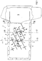
- eine Draufsicht auf eine Ölwanne,
- Fig.2
- vergrößert einen Schnitt entlang der Linie II-II gemäß Fig.1 und
- Fig.3
- vergrößert einen Schnitt entlang der Linie III-III gemäß Fig.1.
- Fig. 1
- a top view of an oil pan,
- Fig. 2
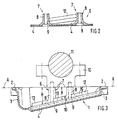
- enlarged a section along the line II-II according to Fig.1 and
- Fig. 3
- enlarges a section along the line III-III according to Fig.1.
Eine Ölwanne 1 einer nicht gezeigten mehrzylindrigen Brennkraftmaschine weist einen in einer Anschlußebene A liegenden Flansch 2 auf, mit dem die Ölwanne 1 an einem nicht gezeigten, horizontal geteilten Kurbelgehäuse der Brennkraftmaschine lösbar gehalten ist. Die Ölwanne 1 wird seitlich durch in Längsrichtung L der Brennkraftmaschine verlaufende Wände 3 begrenzt, zwischen denen sich ein gegenüber der Ebene A geneigter, plattenartiger flacher Boden 4 erstreckt, der an einem Ende der Ölwanne 1 in den als Ölsumpf 5 ausgebildeten tiefen Teil übergeht.
In quer zu der Längsrichtung L verlaufenden, parallelen Ebenen E1, E2 sind Stützen 6 angeordnet, die sich senkrecht zu der Anschlußebene A von dem Boden 4 aus bis zu dieser Ebene A erstrecken. Diese Stützen 6 sind U-förmig gestaltet, wobei die beiden prallelen Schenkel 7 als Pfeifen 8 ausgebildet sind. Die Pfeifen 8 weisen Durchführungen 9 auf, mittels derer der Boden 4 mit nicht gezeigten Schrauben an Lagerstühle 10 der Kurbelwelle 11 geschraubt wird, wobei die Lagerstühle 10 durch die Anschlußebene A begrenzt werden, so daß der Abstand H zwischen dem Boden 4 und der Ebene A durch die Pfeifen 8 überbrückt ist.
Jeweils eine Pfeife 8 einer Stütze 6 ist über eine einstückig mit dem Boden 4 ausgebildete Rippe 12 an eine diagonal gegenüberliegende Pfeife 8 einer benachbarten Stütze 6 angebunden. Benachbart der Rippe 12 angeordnete Rippen 13 nehmen jeweils eine Pfeife 8 auf. Außerhalb der Stützen 6 sind weitere Rippen 14 auf dem Boden 4 angeordnet.
Durch quer zu den Rippen 12, 13, 14 und den Pfeifen 8 verlaufende, kurze Stützrippen 15 wird die Stabilität der Ölwanne 1 weiter erhöht.An oil pan 1 of a multi-cylinder internal combustion engine, not shown, has a
Each
The stability of the oil pan 1 is further increased by
Claims (4)
- Oil pan (1) of a multi-cylinder internal combustion engine, which is held on the lower part of a horizontally divided crankcase in a horizontal plane of connection (A), and having supports (6) which extend from a base (4) of the oil pan (1) running in a substantially flat manner to bearing seats (10) which hold a crankshaft in the crankcase, the supports (6) being screwed to the bearing seats (10) and extending, designed in the form of a U, transversely with respect to the longitudinal direction (L) of the internal combustion engine in parallel planes (E1, E2) and being constructed in one piece with the base (4) as pipes (8) receiving screws, characterized in that the supports (6) extend as far as the plane of connection (A), at least one pipe (8) of each support (6) being connected diagonally to a pipe (8) of an adjacent support (6) by means of a rib (12).
- Oil pan according to Claim 1, characterized in that the supports (6) are arranged in the region of central bearing seats (10).
- Oil pan according to Claim 1, characterized in that the supports (6) bear directly against the bearing seats (10).
- Oil pan according to Claim 1, characterized in that the base (4) is arranged inclined with respect to the plane of connection (A) and further ribs (13, 14) acting as an oil plane are arranged running parallel to the rib (12).
Applications Claiming Priority (2)
| Application Number | Priority Date | Filing Date | Title |
|---|---|---|---|
| DE4014788 | 1990-05-09 | ||
| DE4014788A DE4014788C1 (en) | 1990-05-09 | 1990-05-09 |
Publications (2)
| Publication Number | Publication Date |
|---|---|
| EP0455931A1 EP0455931A1 (en) | 1991-11-13 |
| EP0455931B1 true EP0455931B1 (en) | 1994-03-09 |
Family
ID=6405978
Family Applications (1)
| Application Number | Title | Priority Date | Filing Date |
|---|---|---|---|
| EP91100664A Expired - Lifetime EP0455931B1 (en) | 1990-05-09 | 1991-01-21 | Oil pan for internal combustion engine |
Country Status (4)
| Country | Link |
|---|---|
| US (1) | US5158053A (en) |
| EP (1) | EP0455931B1 (en) |
| JP (1) | JPH04228861A (en) |
| DE (2) | DE4014788C1 (en) |
Cited By (1)
| Publication number | Priority date | Publication date | Assignee | Title |
|---|---|---|---|---|
| DE102019112758A1 (en) * | 2019-05-15 | 2020-11-19 | Otto-Von-Guericke-Universität Magdeburg | Light oil pan with integrated thermal insulation and vibration damping |
Families Citing this family (13)
| Publication number | Priority date | Publication date | Assignee | Title |
|---|---|---|---|---|
| US5456227A (en) * | 1994-08-03 | 1995-10-10 | Nelson Metal Products Corporation | Structural baffle for internal combustion engine |
| DE19619977C2 (en) * | 1996-05-17 | 1998-07-02 | Daimler Benz Ag | Oil pan for an internal combustion engine |
| US6502721B2 (en) | 1996-08-26 | 2003-01-07 | Bobrick Washroom Equipment, Inc. | Washing system with auxiliary reservoir |
| DE19746032C2 (en) * | 1996-10-21 | 2001-02-01 | Nissan Motor | Oil pan assembly for internal combustion engine |
| FR2779478B1 (en) * | 1998-06-08 | 2000-12-15 | Renault Vehicules Ind | OIL TANK FOR A MOTOR VEHICLE ENGINE GROUP |
| US6019071A (en) * | 1998-09-22 | 2000-02-01 | Chrysler Corporation | Engine windage tray |
| US6257193B1 (en) | 1999-09-16 | 2001-07-10 | International Truck And Engine Corporation | Engine with a direct passage from the oil reservoir to the oil pump |
| MY137444A (en) * | 2000-12-21 | 2009-01-30 | Petroliam Nasional Berhad | Oil pan for automobile engine |
| US6530354B1 (en) * | 2002-02-19 | 2003-03-11 | General Motors Corporation | Oil pan with vertical baffles |
| FR2892481A1 (en) * | 2005-10-24 | 2007-04-27 | Renault Sas | Vibration dampening device for engine, has bearing housing integrated with cylinder casing, and elements arranged between bearing cap and oil casing and engaged with cap and oil casing, where elements are fixed to boss of oil casing |
| DE102011007567A1 (en) | 2011-04-18 | 2012-10-18 | Bayerische Motoren Werke Aktiengesellschaft | Lubricant pan for an internal combustion engine |
| US10865671B2 (en) | 2015-04-28 | 2020-12-15 | Toyota Motor Engineering & Manufacturing North America, Inc. | Oil pan assembly |
| US9567880B2 (en) | 2015-04-28 | 2017-02-14 | Toyota Motor Engineering & Manufacturing North America, Inc. | Oil pan assembly |
Citations (1)
| Publication number | Priority date | Publication date | Assignee | Title |
|---|---|---|---|---|
| DE3624325C1 (en) * | 1986-07-18 | 1993-03-04 | Bayerische Motoren Werke Ag | Oil pan |
Family Cites Families (8)
| Publication number | Priority date | Publication date | Assignee | Title |
|---|---|---|---|---|
| US4101003A (en) * | 1977-01-12 | 1978-07-18 | Cummins Engine Company, Inc. | Isolated oil pan assembly |
| JPS56145633U (en) * | 1980-04-02 | 1981-11-02 | ||
| JPS57102540A (en) * | 1980-12-16 | 1982-06-25 | Mazda Motor Corp | Vibration-preventing structure for cylinder block |
| DE3465758D1 (en) * | 1983-12-02 | 1987-10-08 | Austin Rover Group | Internal combustion engine |
| DE3444838C2 (en) * | 1984-12-08 | 1986-10-30 | Bayerische Motoren Werke AG, 8000 München | Housing for reciprocating internal combustion engine, in particular engine block |
| JPH0533720Y2 (en) * | 1987-04-24 | 1993-08-26 | ||
| DE3731734A1 (en) * | 1987-09-21 | 1989-04-06 | Fritz Hildebrandt | Machine with hydraulic cylinder |
| JPH071025B2 (en) * | 1988-04-05 | 1995-01-11 | マツダ株式会社 | Engine cylinder block reinforcement device |
-
1990
- 1990-05-09 DE DE4014788A patent/DE4014788C1/de not_active Expired - Lifetime
-
1991
- 1991-01-21 DE DE91100664T patent/DE59101126D1/en not_active Expired - Fee Related
- 1991-01-21 EP EP91100664A patent/EP0455931B1/en not_active Expired - Lifetime
- 1991-05-02 US US07/694,550 patent/US5158053A/en not_active Expired - Fee Related
- 1991-05-09 JP JP3104399A patent/JPH04228861A/en active Pending
Patent Citations (1)
| Publication number | Priority date | Publication date | Assignee | Title |
|---|---|---|---|---|
| DE3624325C1 (en) * | 1986-07-18 | 1993-03-04 | Bayerische Motoren Werke Ag | Oil pan |
Cited By (1)
| Publication number | Priority date | Publication date | Assignee | Title |
|---|---|---|---|---|
| DE102019112758A1 (en) * | 2019-05-15 | 2020-11-19 | Otto-Von-Guericke-Universität Magdeburg | Light oil pan with integrated thermal insulation and vibration damping |
Also Published As
| Publication number | Publication date |
|---|---|
| US5158053A (en) | 1992-10-27 |
| DE59101126D1 (en) | 1994-04-14 |
| EP0455931A1 (en) | 1991-11-13 |
| JPH04228861A (en) | 1992-08-18 |
| DE4014788C1 (en) | 1991-03-14 |
Similar Documents
| Publication | Publication Date | Title |
|---|---|---|
| EP0455931B1 (en) | Oil pan for internal combustion engine | |
| DE3830966C1 (en) | ||
| DE3626091A1 (en) | BRACKET CONSTRUCTION FOR ENGINE ACCESSORIES | |
| DE69823581T2 (en) | Intermediate piece for connecting a drive assembly housing with a compressor housing | |
| DE3220724C2 (en) | ||
| WO2005119013A1 (en) | Vibration surpressor | |
| DE102005013841A1 (en) | Cylinder block construction for a motor | |
| DE102008046494A1 (en) | Compensation device for a motor | |
| DE3028788C2 (en) | Reciprocating piston engine with internal combustion | |
| DE3815508C1 (en) | ||
| WO1999063216A1 (en) | Crankcase made of light metal for an internal combustion engine | |
| EP0344415B1 (en) | Mounting system for the engine of an automotive vehicle | |
| DE60107631T2 (en) | Hanging device for vertical V-type engines and for outboard engines | |
| DE2739944A1 (en) | COMBUSTION MACHINE WITH NOISE-INSULATING CASING | |
| DE4110347C2 (en) | Mounting arrangement for a baffle plate in an engine | |
| EP0450252B1 (en) | Combustion engine support comprising an internal combustion engine and a foundation | |
| DE602004011103T2 (en) | ENGINE STORAGE DEVICE | |
| DE20314366U1 (en) | Cylinder head for internal combustion engine, e.g. three-cylinder diesel engine, has top deck and multiple integrally cast rocker shaft pedestals having opposing side walls to correctly space adjacent rocker arms on each side of pedestal | |
| DE102007030611A1 (en) | Oil pan arrangement, has sound damping insert provided for installing chamber, and contact surface of insert adapted for lying against inner wall surface of wall constructions with pre-stressing | |
| DE3817320A1 (en) | Noise-damped unit | |
| DE19622678C1 (en) | Multi-cylinder, internal combustion engine | |
| DE10204973C1 (en) | Mechanically-loadable oscillation damping system has coupling between oscillating mass and carrier provided by projecting pins fitting into bores in damping element | |
| DE4215051C2 (en) | Bearing arrangement | |
| DE4325509C2 (en) | Device for damping vibrations on crankshafts | |
| DE4128208C2 (en) | Crankcase |
Legal Events
| Date | Code | Title | Description |
|---|---|---|---|
| PUAI | Public reference made under article 153(3) epc to a published international application that has entered the european phase |
Free format text: ORIGINAL CODE: 0009012 |
|
| AK | Designated contracting states |
Kind code of ref document: A1 Designated state(s): DE FR GB IT SE |
|
| 17P | Request for examination filed |
Effective date: 19920313 |
|
| 17Q | First examination report despatched |
Effective date: 19920525 |
|
| ITF | It: translation for a ep patent filed |
Owner name: DE DOMINICIS & MAYER S. |
|
| GRAA | (expected) grant |
Free format text: ORIGINAL CODE: 0009210 |
|
| AK | Designated contracting states |
Kind code of ref document: B1 Designated state(s): DE FR GB IT SE |
|
| REF | Corresponds to: |
Ref document number: 59101126 Country of ref document: DE Date of ref document: 19940414 |
|
| GBT | Gb: translation of ep patent filed (gb section 77(6)(a)/1977) |
Effective date: 19940324 |
|
| ET | Fr: translation filed | ||
| PLBE | No opposition filed within time limit |
Free format text: ORIGINAL CODE: 0009261 |
|
| STAA | Information on the status of an ep patent application or granted ep patent |
Free format text: STATUS: NO OPPOSITION FILED WITHIN TIME LIMIT |
|
| EAL | Se: european patent in force in sweden |
Ref document number: 91100664.1 |
|
| 26N | No opposition filed | ||
| PGFP | Annual fee paid to national office [announced via postgrant information from national office to epo] |
Ref country code: FR Payment date: 19951228 Year of fee payment: 6 |
|
| PG25 | Lapsed in a contracting state [announced via postgrant information from national office to epo] |
Ref country code: FR Effective date: 19970930 |
|
| REG | Reference to a national code |
Ref country code: FR Ref legal event code: ST |
|
| PGFP | Annual fee paid to national office [announced via postgrant information from national office to epo] |
Ref country code: SE Payment date: 19971223 Year of fee payment: 8 |
|
| PGFP | Annual fee paid to national office [announced via postgrant information from national office to epo] |
Ref country code: GB Payment date: 19980112 Year of fee payment: 8 |
|
| PGFP | Annual fee paid to national office [announced via postgrant information from national office to epo] |
Ref country code: DE Payment date: 19980116 Year of fee payment: 8 |
|
| REG | Reference to a national code |
Ref country code: GB Ref legal event code: 746 Effective date: 19980128 |
|
| PG25 | Lapsed in a contracting state [announced via postgrant information from national office to epo] |
Ref country code: GB Free format text: LAPSE BECAUSE OF NON-PAYMENT OF DUE FEES Effective date: 19990121 |
|
| PG25 | Lapsed in a contracting state [announced via postgrant information from national office to epo] |
Ref country code: SE Free format text: LAPSE BECAUSE OF NON-PAYMENT OF DUE FEES Effective date: 19990122 |
|
| GBPC | Gb: european patent ceased through non-payment of renewal fee |
Effective date: 19990121 |
|
| PG25 | Lapsed in a contracting state [announced via postgrant information from national office to epo] |
Ref country code: DE Free format text: LAPSE BECAUSE OF NON-PAYMENT OF DUE FEES Effective date: 19991103 |
|
| PG25 | Lapsed in a contracting state [announced via postgrant information from national office to epo] |
Ref country code: IT Free format text: LAPSE BECAUSE OF NON-PAYMENT OF DUE FEES;WARNING: LAPSES OF ITALIAN PATENTS WITH EFFECTIVE DATE BEFORE 2007 MAY HAVE OCCURRED AT ANY TIME BEFORE 2007. THE CORRECT EFFECTIVE DATE MAY BE DIFFERENT FROM THE ONE RECORDED. Effective date: 20050121 |