EP0455855A1 - Method and device for the manufacture of medical in particular dental, prosthesis - Google Patents
Method and device for the manufacture of medical in particular dental, prosthesis Download PDFInfo
- Publication number
- EP0455855A1 EP0455855A1 EP90108743A EP90108743A EP0455855A1 EP 0455855 A1 EP0455855 A1 EP 0455855A1 EP 90108743 A EP90108743 A EP 90108743A EP 90108743 A EP90108743 A EP 90108743A EP 0455855 A1 EP0455855 A1 EP 0455855A1
- Authority
- EP
- European Patent Office
- Prior art keywords
- model
- fitting body
- measuring device
- tool
- measured
- Prior art date
- Legal status (The legal status is an assumption and is not a legal conclusion. Google has not performed a legal analysis and makes no representation as to the accuracy of the status listed.)
- Granted
Links
Images

Classifications
-
- A—HUMAN NECESSITIES
- A61—MEDICAL OR VETERINARY SCIENCE; HYGIENE
- A61C—DENTISTRY; APPARATUS OR METHODS FOR ORAL OR DENTAL HYGIENE
- A61C13/00—Dental prostheses; Making same
- A61C13/0003—Making bridge-work, inlays, implants or the like
- A61C13/0006—Production methods
- A61C13/0009—Production methods using a copying machine
-
- A—HUMAN NECESSITIES
- A61—MEDICAL OR VETERINARY SCIENCE; HYGIENE
- A61C—DENTISTRY; APPARATUS OR METHODS FOR ORAL OR DENTAL HYGIENE
- A61C13/00—Dental prostheses; Making same
- A61C13/0003—Making bridge-work, inlays, implants or the like
- A61C13/0004—Computer-assisted sizing or machining of dental prostheses
-
- G—PHYSICS
- G05—CONTROLLING; REGULATING
- G05B—CONTROL OR REGULATING SYSTEMS IN GENERAL; FUNCTIONAL ELEMENTS OF SUCH SYSTEMS; MONITORING OR TESTING ARRANGEMENTS FOR SUCH SYSTEMS OR ELEMENTS
- G05B19/00—Programme-control systems
- G05B19/02—Programme-control systems electric
- G05B19/42—Recording and playback systems, i.e. in which the programme is recorded from a cycle of operations, e.g. the cycle of operations being manually controlled, after which this record is played back on the same machine
- G05B19/4202—Recording and playback systems, i.e. in which the programme is recorded from a cycle of operations, e.g. the cycle of operations being manually controlled, after which this record is played back on the same machine preparation of the programme medium using a drawing, a model
- G05B19/4207—Recording and playback systems, i.e. in which the programme is recorded from a cycle of operations, e.g. the cycle of operations being manually controlled, after which this record is played back on the same machine preparation of the programme medium using a drawing, a model in which a model is traced or scanned and corresponding data recorded
-
- A—HUMAN NECESSITIES
- A61—MEDICAL OR VETERINARY SCIENCE; HYGIENE
- A61C—DENTISTRY; APPARATUS OR METHODS FOR ORAL OR DENTAL HYGIENE
- A61C13/00—Dental prostheses; Making same
- A61C13/0003—Making bridge-work, inlays, implants or the like
- A61C13/0022—Blanks or green, unfinished dental restoration parts
-
- G—PHYSICS
- G16—INFORMATION AND COMMUNICATION TECHNOLOGY [ICT] SPECIALLY ADAPTED FOR SPECIFIC APPLICATION FIELDS
- G16H—HEALTHCARE INFORMATICS, i.e. INFORMATION AND COMMUNICATION TECHNOLOGY [ICT] SPECIALLY ADAPTED FOR THE HANDLING OR PROCESSING OF MEDICAL OR HEALTHCARE DATA
- G16H20/00—ICT specially adapted for therapies or health-improving plans, e.g. for handling prescriptions, for steering therapy or for monitoring patient compliance
- G16H20/40—ICT specially adapted for therapies or health-improving plans, e.g. for handling prescriptions, for steering therapy or for monitoring patient compliance relating to mechanical, radiation or invasive therapies, e.g. surgery, laser therapy, dialysis or acupuncture
Definitions
- the invention relates to a method for producing medical, in particular dental, prosthetic fitting bodies and a device for carrying out the method.
- prosthetic fitting body should be understood here to mean both alloplastic as well as endoprosthetic and exoprosthetic fitting bodies. In the dental field, these can be inlays, onlays, crowns, bridges, prostheses or even implants.
- the procedure is normally that an impression is first taken of the prepared site. Based on the impression, a working model (positive model) is then created in the laboratory, from which a casting model (negative model) is finally made. Wax is applied to the working model, which is usually a plaster model, as a molding material.
- the wax is cut with a suitable contouring tool, e.g. a milling machine, machined. During this process, it must be ensured that the wax layer has a certain minimum thickness on all parts of the peripheral surface.
- Another way of producing prosthetic fitting bodies is that liquid plastic is introduced into a negative mold corresponding to the prosthetic fitting body and the plastic is then, e.g. is polymerized by means of UV rays or heat.
- EP-A-0 182 098 and EP-A-0 054 785 describe a method and a device for producing ready-to-use dental fitting bodies.
- the preparation site in the patient's mouth is scanned with the aid of an optical camera.
- the measured values are then entered into a computer, where they are processed together with further design data to form control data, with which the fitting body is finally made from a suitable material with the aid of a CNC processing machine.
- this method is very advantageous, the technical effort could be reduced even further, in particular because of the relatively complicated structure of the camera.
- the object of the invention specified in claim 1 is to provide a method for creating a prosthetic fitting body which is, in contrast, simpler and less expensive, and an apparatus for carrying out the method.
- the present invention is based on the fact that the optical scanning is not carried out on site at the preparation site, but rather externally in an already existing processing machine, with the aid of which the fitting body is created.
- a relatively simple impression can advantageously be taken, which is either inserted directly into the processing machine as a negative model and then measured three-dimensionally there, or from which a positive model, for example a plaster model, is first created, which is measured in the processing machine.
- a positive model for example a plaster model
- Control signals are formed from the measurement data obtained, with which drive and servomotors for processing tools are controlled, which finally manufacture the fitting body from a workpiece blank in accordance with the contours measured using the model and then calculated.
- the invention is based on the knowledge that the parts which are necessary for the machining of the fitting body and which the processing machine must have, in particular the precisely movable and controllable parts (degrees of freedom) of the processing machine for the measurements of the model.
- the holding and clamping device of the processing machine is used twice, first to hold the model, preferably for optical measurement, and then to hold the workpiece blank for ready-to-use shaping of the fitting body. It is particularly advantageous to carry out the measurement with the aid of an optical measuring device, which can either be fixed in the housing of the processing machine or on an adjustable tool carrier head.
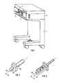
- FIG. 1 shows a diagrammatic representation of the overall arrangement of the device according to the invention in one embodiment for producing a tooth restoration fitting body.
- the device contains a mobile stand 1 with an attached housing 2, which contains a processing machine, generally designated 3. The individual components of this processing machine are described in more detail with reference to the following figure.
- the housing 2 forms a processing chamber 4, which can be closed by means of a preferably transparent cover 5 when the machine is in operation.
- Figure 2 shows the processing machine seen from above in section.
- the housing 2 accommodates all three components important for the production of the fitting body, namely a receiving device 7, a measuring device 8 and a processing device 9.
- the holding device 7 serves on the one hand to hold a model of the fitting body or of the object in which the fitting body is to be inserted later, and on the other hand (alternatively) to hold a workpiece blank made of a suitable material from which the fitting body is to be made.
- the model can be a positive or negative model of the fitting body or of the object.
- FIG. 4 shows a positive model of a MOD inlay fitting body
- FIG. 5 shows a positive model of a prepared tooth object.
- FIG. 2 shows the processing machine in a phase prepared for processing such a MOD inlay.
- the receiving device 7 is therefore already equipped with a workpiece blank 10, for example made of dental ceramic.
- the receiving device 7 contains a spindle 11 designed as a hollow shaft, which on its end facing away from the workpiece blank 10 has a spindle nut 12 which cooperates with a threaded spindle 13 which is directly coupled to the drive shaft of a drive motor 14 fastened to the housing 2.
- a gear 15 is connected in a rotationally fixed manner to the spindle 11, which gear meshes with a toothed shaft 16, which is mounted between two walls of the housing, which are not described in more detail, and is likewise directly coupled to the drive shaft of a second drive motor 17.
- the drive motor 17 serves to set the spindle 11 in a rotational movement, while a linear movement (longitudinal feed) of the spindle 11 is achieved with the drive 14. If both drive motors 14, 17 run simultaneously, the object held in the front end of the spindle 11 facing the processing chamber 4 by means of a clamping device, generally designated 18, in the present case the workpiece blank 10, is moved spirally. It is understandable that the spindle 11 is guided in a suitable longitudinal and rotary bearing.
- the measuring device 8 consists essentially of a light source 20 which generates a sharply focused light beam which can be aligned with the object held in the receiving device 7, and an optical sensor 21 on which the light spot projected by the light source 20 onto the object is imaged.
- the processing device 9 consists of two mutually opposite spindle arrangements 22 and 35 which, apart from the arrangement of the tools, are of completely identical design. Therefore, only the structure of the spindle arrangement 22 on the right in the figure is explained in more detail below.
- the spindle arrangement 22 contains a spindle 23 designed as a hollow shaft, one of which End protrudes into the processing chamber 4 and carries a tool carrier head 24 there.
- the tool carrier head 24 is connected in a rotationally fixed manner to the spindle 23 and contains in the center an electric motor indicated by 25, the drive shafts on both sides of which drive two similar machining tools 26, 26 'via a gear (not specified).
- a spindle nut 27 is fastened to the spindle 23 and engages with a threaded spindle 29 driven by a drive motor 28. With these drive elements, the spindle 23 can be adjusted in the axial direction.
- the entire tool carrier head 24 can be rotated about the spindle axis, specifically by at least 90 °, but preferably by 180 °.
- a rotation through 90 ° is particularly indicated in order to bring the tool carrier head from the work position shown in the figure, which is suitable for workpiece machining, to a basic or rest position, in which access to the workpiece blank 10 is facilitated on the one hand and no obstruction during measurement on the other hand of the model, as will be explained later, with the aid of the measuring device 20, 21.
- stepper motors as drive motors, which can be controlled in any small step units.
- the stepper motors are provided with feedback.
- Such feedback can consist, for example, in the fact that in the vicinity of the feed spindle, or also coupled to it, on a resistance, capacitance, inductance, ultrasound, magnet and / or optical basis
- Sensor means are provided which are electrically connected to the associated stepper motors via a computer. With the help of such a measuring system, it is possible to increase the accuracy of the spindle movements.
- a fork light barrier 33 is provided on a housing wall, which cooperates with a ring 34 of the gearwheel 30 interrupted by a slot in such a way that the spindle position is exactly defined, both in relation to the Rotational position as well as in relation to the position in the axial direction. While the position in the direction of the feed axis is detected by immersing the ring 34 in the fork light barrier 33, the angular position of the spindle is detected by a signal when the slot 34 interrupting the slot 34 is passed through the light barrier.
- the tool carrier head 36 arranged opposite is constructed identically with regard to the adjustment of the spindle; since the tools held there are not finger-shaped machining tools, as in the case of the tools 26, 26 ', but rather disk-shaped tools (items 37, 37'), the angular gear provided in the tool carrier head 24 is omitted.
- the two drive shafts of the electric motor 38 arranged in the tool carrier head 36 thus drive the two tools 37, 37 'directly.
- the two drive motors for adjusting the spindle 39 (analogous to the spindle 23) are denoted by 40 and 41.
- a positive model is first created from the fitting body to be created, that is to say the MOD inlay.
- an impression is first made of the prepared tooth, in which the fitting body is to be inserted later, and a positive model of the inlay is made from this impression.
- This positive model designated 42 in the upper part of FIG. 3 and shown enlarged in FIG. 4, can be made of plaster or plastic and mounted on a peg-shaped carrier 43.
- the model 42 is inserted with the aid of the carrier 43 with a defined stop into the quick-release device of the receiving device 7, which is denoted by 18. Then the optical measurement of the model begins.
- the light source 20 FIG.
- the model is measured using the triangulation method with a specific (as small as possible) parallax angle between the projection and observation beam path. This method is known per se and is used, for example, in 3-D laser scanners.
- the model is moved spirally with the aid of the spindle 11 and the two servomotors 14 and 17 with sufficient fineness (for example with a pitch of 25 ⁇ m).
- the measured values are digitized in an A / D converter 46 and then fed to a memory 47 of a computing unit 48.
- the measured values are converted into feed values, with which the actuating and drive motors 14, 17, 25, 28, 31, 38, 40, 41 are then controlled via a corresponding interface 49 in the processing phase.
- the workpiece blank designated by 10 in FIG. 2 is inserted into the receiving device 7 (lower image phase in FIG. 3).
- the fitting body is then worked out of the workpiece blank according to the calculated control program with the aid of the two machining tools 26, 37 which are arranged in the tool carrier heads 24 and 36.
- FIG. 5 shows such a positive model of a prepared row of teeth.
- this variant would be technically more complex overall, in particular because of the larger computer that would be required, but it would have certain advantages when creating palate plates for full dentures, because here the impression could be optically scanned as a negative model and directly from this negative model Fit body, i.e. create the palate plate.
- the optical measuring device 20, 21 on one of the tool carrier heads 24, 35.
- the sensor could then be brought into an optimal measuring position via defined movements.
- the movements which are then generated by the movements of the tool spindles are known to the computer and can be superimposed on the actual sensor measured value as a correction.
- the sensor can be designed so that it does not determine a measured value over the distance to the surface of the model, but only signals whether the surface is at a certain distance or not. Then the sensor is moved during the measurement until it is at this certain distance; the measured value of the surface then results from knowledge of the travel path.
- Suitable detectors would be, for example, detectors that work on the principle of the confocal microscope or other focus detectors.
- the movement of the sensor can also be used to measure the model from different viewing directions.
Abstract
Description
Die Erfindung betrifft ein Verfahren zur Erstellung von medizinischen, insbesondere zahnmedizinischen Prothetik-Paßkörpern sowie eine Vorrichtung zur Durchführung des Verfahrens. Unter dem Begriff "Prothetik-Paßkörper" sollen hier sowohl alloplastische also auch endo- und exoprothetische Paßkörper verstanden werden. Im zahnmedizinischen Bereich können diese Inlays, Onlays, Kronen, Brücken, Prothesen oder auch Implantate sein.The invention relates to a method for producing medical, in particular dental, prosthetic fitting bodies and a device for carrying out the method. The term "prosthetic fitting body" should be understood here to mean both alloplastic as well as endoprosthetic and exoprosthetic fitting bodies. In the dental field, these can be inlays, onlays, crowns, bridges, prostheses or even implants.
Bei der Herstellung solcher Paßkörper wird normalerweise so vorgegangen, daß zunächst von der präparierten Stelle ein Abdruck genommen wird. Anhand des Abdruckes wird im Labor dann ein Arbeitsmodell (Positivmodell) erstellt, von dem schließlich ein Gießmodell (Negativmodell) angefertigt wird. Auf das Arbeitsmodell, welches in der Regel ein Gipsmodell ist, wird Wachs als Formmaterial aufgetragen. Das Wachs wird entsprechend der Form des zu erstellenden Paßkörpers mit einem geeigneten Konturenwerkzeug, z.B. einer Fräse, bearbeitet. Bei diesem Vorgang ist sicherzustellen, daß auf allen Teilen der Umfangsfläche die Wachsschicht eine bestimmte Mindeststärke aufweist.In the manufacture of such fitting bodies, the procedure is normally that an impression is first taken of the prepared site. Based on the impression, a working model (positive model) is then created in the laboratory, from which a casting model (negative model) is finally made. Wax is applied to the working model, which is usually a plaster model, as a molding material. The wax is cut with a suitable contouring tool, e.g. a milling machine, machined. During this process, it must be ensured that the wax layer has a certain minimum thickness on all parts of the peripheral surface.
Eine andere Art der Herstellung von Prothetik-Paßkörpern besteht darin, daß flüssiger Kunststoff in eine dem Prothetik-Paßkörper entsprechende Negativform eingebracht wird und der Kunststoff anschließend, z.B. mittels UV-Strahlen oder Wärme auspolymerisiert wird.Another way of producing prosthetic fitting bodies is that liquid plastic is introduced into a negative mold corresponding to the prosthetic fitting body and the plastic is then, e.g. is polymerized by means of UV rays or heat.
In aller Regel führen die vorgenannten Verfahren zu unerwünschten Formveränderungen beim Erstarren oder Abkühlen.As a rule, the aforementioned methods lead to undesirable changes in shape when solidifying or cooling.
Die Herstellung der Paßkörper im Gieß- oder Polymerisationsverfahren mit den hierzu notwendigen vorbereitenden Schritten erfordert außerdem einen erheblichen Aufwand, viel Erfahrung und außerordentlich genaue Arbeit.The production of the fitting body in the casting or polymerization process with the necessary preparatory steps also requires considerable effort, a lot of experience and extremely precise work.
In der EP-A-0 182 098 und EP-A-0 054 785 werden ein Verfahren sowie eine Vorrichtung zur Herstellung von verwendungsfertigen zahntechnischen Paßkörper beschrieben. Bei diesem Verfahren wird mit Hilfe einer optischen Kamera die Präparationsstelle im Patientenmund abgetastet. Die Meßwerte werden sodann in einen Rechner eingegeben, wo sie zusammen mit weiteren Konstruktionsdaten zu Steuerdaten verarbeitet werden, mit denen schließlich unter Zuhilfenahme einer CNC-Bearbeitungsmaschine der Paßkörper aus einem geeigneten Material ausgearbeitet wird. Obgleich dieses Verfahren sehr vorteilhaft ist, könnte, insbesondere wegen des relativ komplizierten Aufbaus der Kamera, der technische Aufwand noch weiter reduziert werden.EP-A-0 182 098 and EP-A-0 054 785 describe a method and a device for producing ready-to-use dental fitting bodies. With this method, the preparation site in the patient's mouth is scanned with the aid of an optical camera. The measured values are then entered into a computer, where they are processed together with further design data to form control data, with which the fitting body is finally made from a suitable material with the aid of a CNC processing machine. Although this method is very advantageous, the technical effort could be reduced even further, in particular because of the relatively complicated structure of the camera.
Der im Anspruch 1 angegebenen Erfindung liegt die Aufgabe zugrunde, ein demgegenüber einfacheres und preisgünstigeres Verfahren zur Erstellung eines Prothetik-Paßkörpers sowie eine Vorrichtung zur Durchführung des Verfahrens anzugeben.The object of the invention specified in claim 1 is to provide a method for creating a prosthetic fitting body which is, in contrast, simpler and less expensive, and an apparatus for carrying out the method.
Die vorliegende Erfindung geht davon aus, die optische Abtastung nicht vor Ort an der Präparationsstelle vorzunehmen, sondern extern in einer ohnehin vorhandenen Bearbeitungsmaschine, mit deren Hilfe der Paßkörper erstellt wird. Anstelle der bisher notwendigen, relativ aufwendigen optischen Abtastung der Präparationsstelle kann vorteilhafterweise ein relativ einfach vorzunehmender Abdruck treten, der entweder direkt als Negativmodell in die Bearbeitungsmaschine eingesetzt und dort anschließend dreidimensional vermessen wird oder von dem zunächst ein Positivmodell,z.B. ein Gipsmodell, erstellt wird, welches in der Bearbeitungsmaschine vermessen wird. Besonders vorteilhaft ist es, von dem zu erstellenden Paßkörper ein Positiv-Modell anzufertigen und dieses dann in der Bearbeitungsmaschine zu vermessen. Aus den gewonnenen Meßdaten werden Steuersignale gebildet, mit denen Antriebs- und Stellmotoren für Bearbeitungswerkzeuge angesteuert werden, die aus einem Werkstückrohling entsprechend den anhand des Modells ausgemessenen und anschließend errechneten Konturen schließlich den Paßkörper fertigen.The present invention is based on the fact that the optical scanning is not carried out on site at the preparation site, but rather externally in an already existing processing machine, with the aid of which the fitting body is created. Instead of the previously required, relatively complex optical scanning of the preparation site, a relatively simple impression can advantageously be taken, which is either inserted directly into the processing machine as a negative model and then measured three-dimensionally there, or from which a positive model, for example a plaster model, is first created, which is measured in the processing machine. It is particularly advantageous to make a positive model of the fitting body to be created and then to do this in the processing machine to measure. Control signals are formed from the measurement data obtained, with which drive and servomotors for processing tools are controlled, which finally manufacture the fitting body from a workpiece blank in accordance with the contours measured using the model and then calculated.
Die Erfindung basiert auf der Erkenntnis, die für das Bearbeiten des Paßkörpers ohnehin notwendigen Teile, die die Bearbeitungsmaschine aufweisen muß, insbesondere die exakt bewegbaren und steuerbaren Teile (Freiheitsgrade) der Bearbeitungsmaschine für die Ausmessungen des Modells zu nutzen. Die Aufnahme-und Spanneinrichtung der Bearbeitungsmaschine wird so zweifach genutzt, zunächst, um das Modell zum vorzugsweise optischen Ausmessen, und anschließend, um den Werkstückrohling zur verwendungsfertigen formgebenden Ausarbeitung des Paßkörpers aufzunehmen. Besonders vorteilhaft ist es, das Ausmessen mit Hilfe einer optischen Vermessungseinrichtung durchzuführen, die entweder ortsfest im Gehäuse der Bearbeitungsmaschine oder auf einem verstellbar angeordneten Werkzeugträgerkopf angeordnet sein kann.The invention is based on the knowledge that the parts which are necessary for the machining of the fitting body and which the processing machine must have, in particular the precisely movable and controllable parts (degrees of freedom) of the processing machine for the measurements of the model. The holding and clamping device of the processing machine is used twice, first to hold the model, preferably for optical measurement, and then to hold the workpiece blank for ready-to-use shaping of the fitting body. It is particularly advantageous to carry out the measurement with the aid of an optical measuring device, which can either be fixed in the housing of the processing machine or on an adjustable tool carrier head.
Weitere Vorteile ergeben sich aus der nachstehenden Beschreibung eines Ausführungsbeispieles. Es zeigen:
- Figur 1 eine Gesamtansicht der erfindungsgemäßen Vorrichtung in schaubildlicher Darstellung,
Figur 2 einen Teil der Vorrichtung nach Figur 1 in einer Schnittdarstellung,- Figur 3 eine schematisierte Darstellung der Steuerung der Antriebs- und Stellmotoren für die Vermessungs- und Bearbeitungsphase,
- Figur 4 eine erste Ausführungsform eines Modells,
Figur 5 eine zweite Ausführungsform eines Modells.
- FIG. 1 shows an overall view of the device according to the invention in a diagrammatic representation,
- FIG. 2 shows part of the device according to FIG. 1 in a sectional illustration,
- FIG. 3 shows a schematic representation of the control of the drive and servomotors for the measurement and processing phase,
- FIG. 4 shows a first embodiment of a model,
- Figure 5 shows a second embodiment of a model.
Die Figur 1 zeigt in einer schaubildlichen Darstellung die Gesamtanordnung der erfindungsgemäßen Vorrichtung in einer Ausführungsform zur Herstellung eines Zahnrestaurations-Paßkörpers. Die Vorrichtung enthält ein Fahrstativ 1 mit einem aufgesetzten Gehäuse 2, welches eine allgemein mit 3 bezeichnete Bearbeitungsmaschine enthält. Die einzelnen Komponenten dieser Bearbeitungsmaschine werden anhand der nachfolgenden Figur näher beschrieben. Das Gehäuse 2 bildet eine Bearbeitungskammer 4, die mittels eine vorzugsweise durchsichtigen Deckels 5 bei Betrieb der Maschine geschlossen werden kann.FIG. 1 shows a diagrammatic representation of the overall arrangement of the device according to the invention in one embodiment for producing a tooth restoration fitting body. The device contains a mobile stand 1 with an attached
Die Figur 2 zeigt die Bearbeitungsmaschine von oben gesehen im Schnitt. Das Gehäuse 2 nimmt alle drei für die Herstellung des Paßkörpers wichtigen Komponenten auf, nämlich eine Aufnahmeeinrichtung 7, eine Vermessungseinrichtung 8 sowie eine Bearbeitungseinrichtung 9.Figure 2 shows the processing machine seen from above in section. The
Die Aufnahmeeinrichtung 7 dient einerseits dazu, ein Modell von dem Paßkörper oder von dem Objekt, in das der Paßkörper später eingesetzt werden soll, und andererseits (alternativ) einen Werkstückrohling aus einem geeigneten Material, aus dem der Paßkörper erstellt werden soll, aufzunehmen. Das Modell kann ein Positiv- oder Negativ-Modell vom Paßkörper bzw. von dem Objekt sein. In Figur 4 ist beispielsweise ein Positiv-Modell von einem MOD-Inlay-Paßkörper, in Figur 5 ein Positiv-Modell von einem präparierten Zahnobjekt dargestellt.The holding device 7 serves on the one hand to hold a model of the fitting body or of the object in which the fitting body is to be inserted later, and on the other hand (alternatively) to hold a workpiece blank made of a suitable material from which the fitting body is to be made. The model can be a positive or negative model of the fitting body or of the object. For example, FIG. 4 shows a positive model of a MOD inlay fitting body, and FIG. 5 shows a positive model of a prepared tooth object.
Die Figur 2 zeigt die Bearbeitungsmaschine in einer zur Bearbeitung eines solchen MOD-Inlays vorbereiteten Phase. Die Aufnehmeeinrichtung 7 ist deshalb bereits mit einem Werkstückrohling 10 , z.B. aus Dentalkeramik, bestückt.FIG. 2 shows the processing machine in a phase prepared for processing such a MOD inlay. The receiving device 7 is therefore already equipped with a workpiece blank 10, for example made of dental ceramic.
Die Aufnahmeeinrichtung 7 enthält eine als Hohlwelle ausgebildete Spindel 11, die an ihrem dem Werkstückrohling 10 abgewandten Ende eine Spindelmutter 12 aufweist, die mit einer Gewindespindel 13 zusammenwirkt, welche direkt mit der Antriebswelle eines am Gehäuse 2 befestigten Antriebsmotor 14 gekoppelt ist.The receiving device 7 contains a
Mit der Spindel 11 drehfest verbunden ist ein Zahnrad 15, welches mit einer Zahnwelle 16 in Eingriff steht, die zwischen zwei nicht näher bezeichneten Wandungen des Gehäuses gelagert und ebenfalls direkt mit der Antriebswelle eines zweiten Antriebsmotors 17 gekoppelt ist. Der Antriebsmotor 17 dient dazu, die Spindel 11 in eine Drehbewegung zu versetzen, während mit dem Antrieb 14 eine Linearbewegung (Längsvorschub) der Spindel 11 erzielt wird. Wenn beide Antriebsmotoren 14, 17 gleichzeitig laufen, wird der am vorderen, der Bearbeitungskammer 4 zugewandten Ende der Spindel 11 mittels einer allgemein mit 18 bezeichneten Einspannvorrichtung gehalterte Gegenstand, im vorliegenden Fall der Werkstückrohling 10, spiralförmig bewegt. Es ist verständlich, daß hierzu die Spindel 11 in einem geeigneten Längs- und Drehlager geführt ist.A
Die Vermessungseinrichtung 8 besteht im wesentlichen aus einer Lichtquelle 20, die einen scharf gebündelten, auf den in der Aufnahmeeinrichtung 7 gehalterten Gegenstand ausrichtbaren Lichtstrahl erzeugt, und einem optischen Sensor 21, auf dem der von der Lichtquelle 20 auf den Gegenstand projizierte Lichtfleck abgebildet wird.The measuring device 8 consists essentially of a
Die Bearbeitungseinrichtung 9 besteht aus zwei einander gegenüberliegenden Spindelanordnungen 22 und 35, welche bis auf die Anordnung der Werkzeuge völlig gleich ausgebildet sind. Nachfolgend wird deshalb nur der Aufbau der im Bild rechten Spindelanordnung 22 näher erläutert. Die Spindelanordnung 22 enthält eine als Hohlwelle ausgebildete Spindel 23, deren eines Ende in die Bearbeitungskammer 4 ragt und dort einen Werkzeugträgerkopf 24 trägt. Der Werkzeugträgerkopf 24 ist mit der Spindel 23 drehfest verbunden und enthält mittig einen mit 25 angedeuteten Elektromotor, dessen beidseitige Antriebswellen über ein nicht näher bezeichnetes Getriebe zwei gleichartige Bearbeitungswerkzeuge 26, 26' antreiben.The
An der Spindel 23 ist eine Spindelmutter 27 befestigt, die mit einer von einem Antriebsmotor 28 angetriebenen Gewindespindel 29 in Eingriff steht. Mit diesen Antriebselementen kann die Spindel 23 in Achsrichtung verstellt werden.A
Mit der Spindel 23 drehfest verbunden ist wiederum ein Zahnrad 30, welches mit einer von einem weiteren Antriebsmotor 31 angetriebenen Zahnwelle 32 kämmt. Mit diesem Antriebselement kann der gesamte Werkzeugträgerkopf 24 um die Spindelachse gedreht werden, und zwar um wenigstens 90°, vorzugsweise jedoch um 180°. Ein Drehen um 90° ist insbesondere deshalb angezeigt, um den Werkzeugträgerkopf aus der in der Figur gezeigten, für eine Werkstückbearbeitung geeigneten Arbeitsstellung in eine Grund- oder Ruheposition zu bringen, in der einerseits der Zugang zum Werkstückrohling 10 erleichtert ist und andererseits keine Behinderung beim Ausmessen des Modells, wie später noch erläutert, mit Hilfe der Vermessungeinrichtung 20, 21 gegeben ist.A
Nachdem der Vorschub der Spindeln sehr präzise erfolgen muß, ist es notwendig, die hierzu vorgesehen Antriebsmotoren genau anzusteuern. Zu diesem Zweck ist es vorteilhaft, als Antriebsmotoren Schrittmotoren einzusetzen, die an sich in beliebig kleinen Schritteinheiten angesteuert werden können. Um dennoch Schrittverluste ausgleichen zu können, sind die Schrittmotoren mit einer Rückmeldung versehen. Eine solche Rückmeldung kann z.B. darin bestehen, daß in Nähe der Vorschubspindel, oder auch mit dieser gekuppelt, auf Wiederstands-, Kapazitäts-, Induktivitäts-, Ultraschall-, Magnet- und/oder optischer Basis aufbauende Sensormittel vorgesehen sind, die über einen Rechner mit den zugehörigen Schrittmotoren elektrisch verbunden sind. Mit Hilfe eines solchen Wegemeßsystems ist es möglich, die Genauigkeit der Spindelbewegungen zu erhöhen.After the spindles have to be fed very precisely, it is necessary to precisely control the drive motors provided for this purpose. For this purpose, it is advantageous to use stepper motors as drive motors, which can be controlled in any small step units. In order to be able to compensate for step losses, the stepper motors are provided with feedback. Such feedback can consist, for example, in the fact that in the vicinity of the feed spindle, or also coupled to it, on a resistance, capacitance, inductance, ultrasound, magnet and / or optical basis Sensor means are provided which are electrically connected to the associated stepper motors via a computer. With the help of such a measuring system, it is possible to increase the accuracy of the spindle movements.
Um die Ruhe- oder Ausgangsstellung der Spindeln exakt zu definieren, ist an einer Gehäusewand eine Gabellichtschranke 33 vorgesehen, die mit einem durch einen Schlitz unterbrochenen Ring 34 des Zahnrades 30 derart zusammenwirkt, daß die Spindelstellung exakt definiert ist, und zwar sowohl im bezug auf die Drehstellung als auch in bezug auf die Stellung in axialer Richtung. Während die Position in Richtung der Vorschubachse durch Eintauchen des Ringes 34 in die Gabellichtschranke 33 erfaßt wird, wird die Winkelstellung der Spindel durch ein Signal beim Durchfahren des den Ring 34 unterbrechenden Schlitzes durch die Lichtschranke erfaßt.In order to exactly define the rest or starting position of the spindles, a
Der gegenüberliegend angeordnete Werkzeugträgerkopf 36 ist bezüglich der Verstellung der Spindel gleich aufgebaut; nachdem es sich bei den dort gehalterten Werkzeugen nicht um fingerförmige Bearbeitungswerkzeuge, wie bei den Werkezugen 26, 26', sondern um scheibenförmige Werkzeuge (Pos 37, 37') handelt, entfällt das beim Werkzeugträgerkopf 24 vorgesehene Winkelgetriebe. Die beiden Antriebswellen des im Werkzeugträgerkopf 36 angeordneten Elektromotors 38 treiben also die beiden Werkzeuge 37, 37' direkt an. Die beiden Antriebsmotoren zum Verstellen der Spindel 39 (analog der Spindel 23) sind mit 40 und 41 bezeichnet.The
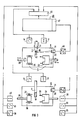
Anhand der Figuren 3 und 4 soll das erfindungsgemäße Verfahren am Beispiel der Erstellung eines MOD-Inlays näher erläutert werden. In Figur 3 der Zeichnung sind die zwei Phasen, einerseits die Vermessungsphase und andererseits die Bearbeitungsphase, sowie die damit zusammenhängende elektrische Verknüpfung der Antriebe schematisch dargestellt.The method according to the invention is to be explained in more detail with reference to FIGS. 3 and 4 using the example of creating a MOD inlay. In Figure 3 of the drawing, the two phases, on the one hand the measurement phase and on the other hand the processing phase, and the associated electrical connection of the drives are shown schematically.
Im Ausführungsbeispiel wird davon ausgegangen, daß von dem zu erstellenden Paßkörper, also dem MOD-Inlay, zunächst ein Positiv-Modell erstellt wird. Hierzu wird von dem präparierten Zahn, in den der Paßkörper später eingesetzt werden soll, zunächst ein Abdruck und von diesem Abdruck ein Positivmodell vom Inlay erstellt. Dieses Positivmodell, im oberen Teil der Figur 3 mit 42 bezeichnet und in Figur 4 schaubildlich vergrößert dargestellt, kann aus Gips oder Kunststoff erstellt werden und auf einen zapfenförmigen Träger 43 montiert sein. Das Modell 42 wird mit Hilfe des Trägers 43 mit definiertem Anschlag in die mit 18 bezeichnete Schnellspanneinrichtung der Aufnahmeeinrichtung 7 eingesetzt. Danach beginnt die optische Vermessung des Modells. Hierzu sendet die Lichtquelle 20 (FIG 2), die vorzugsweise eine Laserdiode sein kann, einen scharf gebündelten Lichtstrahl aus, der exakt auf die Drehachse 45 des Modells 42 bzw. der Vorschubspindel 11 ausgerichtet ist. Der auf dem Modell projizierte Lichtfleck wird von dem ortsfest angeordneten optischen Sensor 21 erfaßt und in elektrische Signale umgewandelt. Hierzu kann ein geeignetes CCD- oder PSD-Element (position sensitive device) vorgesehen werden. Die Vermessung des Modells erfolgt nach dem Triangulationsverfahren mit einem bestimmten (möglichst kleinen) Parallaxenwinkel zwischen Projektions- und Beobachtungsstrahlengang. Dieses Verfahren ist an sich bekannt und wird beispielsweise bei 3-D-Laserscannern angewandt. Während der Vermessung wird das Modell mit Hilfe der Spindel 11 und der beiden Stellmotoren 14 und 17 spiralförmig mit genügender Feinheit (z.B. mit einer Steigung von 25 µm) bewegt. In jeder Stellung wird dabei ein Wert ![]()
![]()
Die Meßwerte werden in einem A/D-Wandler 46 digitalisiert und anschließend einem Speicher 47 einer Recheneinheit 48 zugeführt. In der Recheneinheit 48 werden die Meßwerte in Vorschubwerte umgerechnet, mit denen dann über ein entsprechendes Interface 49 in der Bearbeitungsphase die Stell- und Antriebsmotoren 14, 17, 25, 28, 31, 38, 40, 41 angesteuert werden.The measured values are digitized in an A / D converter 46 and then fed to a
Nach dem Ausmessen des Modells 42 wird in die Aufnahmeeinrichtung 7 der in Figur 2 mit 10 bezeichnete Werkstückrohling eingesetzt (untere Bildphase in FIG 3). In der anschließenden Bearbeitungsphase wird nun mit Hilfe der beiden Bearbeitungswerkzeuge 26, 37, die in den Werkzeugträgerköpfen 24 und 36 angeordnet sind, der Paßkörper aus dem Werkstückrohling entsprechend dem errechneten Steuerprogramm herausgearbeitet.After the measurement of the
Alternativ zu der vorbeschriebenen Verfahrensweise, zunächst von der Präparationsstelle einen Abdruck zu nehmen und davon ein Positiv-Modell vom Paßkörper zu erstellen, ist es denkbar, das Positiv-Modell direkt im Mund mit Hilfe von z.B. Composite-Material zu erstellen. Desgleichen ist es denkbar und im Rahmen der Erfindung möglich, anstelle eines Positiv-Modells vom Paßkörper ein Positv- oder Negativ-Modell von dem Objekt, in das der Paßkörper eingesetzt werden soll, anzufertigen und dieses dann, wie vorbeschrieben, abzutasten. Figur 5 zeigt ein solches Positiv-Modell von einer präparierten Zahnreihe. Bei der optischen Vermessung werden die Außenkonturen des Zahnes sowie die Konturen der mit 44 bezeichneten Kavität erfaßt und aus den Meßwerten dann der Paßkörper errechnet. Diese Variante wäre aber, insbesondere wegen des größeren Rechners, der dazu notwendig wäre, insgesamt technisch aufwendiger, sie hätte jedoch bestimmte Vorteile bei der Erstellung von Gaumenplatten für Vollprothesen, denn hier könnte man den Abdruck sogleich als Negativmodell optisch abtasten und von diesem Negativmodell direkt den Paßkörper, also die Gaumenplatte erstellen. Für die Bearbeitung solcher Prothesenteile ist es vorteilhaft, eine Aufnahmeeinheit vorzusehen, bei der Modell und Werkstück anstelle der beschriebenen kombinierten Dreh- und Vorschubbewegung auf einem Verschiebetisch mit zwei Freiheitsgraden in der Ebene senkrecht zu den Achsen der Werkzeugspindeln verstellt werden.As an alternative to the procedure described above, first taking an impression of the preparation site and creating a positive model of the fitting body, it is conceivable to create the positive model directly in the mouth using, for example, composite material. Likewise, it is conceivable and possible within the scope of the invention to produce a positive or negative model of the object in which the fitting body is to be used instead of a positive model of the fitting body and then to scan it as described above. FIG. 5 shows such a positive model of a prepared row of teeth. During the optical measurement, the outer contours of the tooth and the contours of the cavity denoted by 44 are recorded and the fitting body is then calculated from the measured values. However, this variant would be technically more complex overall, in particular because of the larger computer that would be required, but it would have certain advantages when creating palate plates for full dentures, because here the impression could be optically scanned as a negative model and directly from this negative model Fit body, i.e. create the palate plate. For editing such Prosthetic parts, it is advantageous to provide a receiving unit in which the model and workpiece are adjusted instead of the described combined rotary and feed movement on a sliding table with two degrees of freedom in the plane perpendicular to the axes of the tool spindles.
Um bei gleichem Meßbereich eine bessere Meßgenauigkeit zu erzielen, ist es vorteilhaft, die optische Meßeinrichtung 20, 21 auf einem der Werkzeugträgerköpfe 24, 35 zu montieren. Der Sensor könnte dann über definierte Bewegungen in eine optimale Meßposition gebracht werden. Die Bewegungen, die dann durch die Bewegungen der Werkzeugspindeln erzeugt werden, sind dem Rechner bekannt und können dem eigentlichen Sensormeßwert als Korrektur überlagert werden. Im Extremfall kann der Sensor so gestaltet werden, daß er nicht einen Meßwert über die Entfernung zur Oberfläche des Modells ermittelt, sondern nur signalisiert, ob sich die Oberfläche in einer bestimmten Distanz befindet oder nicht. Dann wird der Sensor bei der Vermessung jeweils so lange verfahren, bis er in dieser bestimmten Distanz ist; der Meßwert der Oberfläche ergibt sich dann aus der Kenntnis des Verfahrweges. Geeignete Detektoren wären zum Beispiel Detektoren, die nach dem Prinzip des konfokalen Mikroskopes arbeiten oder andere Fokus-Detektoren. Abschließend sei darauf hingewiesen, daß die Bewegung des Sensors auch dazu genutzt werden kann, um das Modell aus verschiedenen Blickrichtungen zu vermessen.In order to achieve better measuring accuracy with the same measuring range, it is advantageous to mount the
Claims (11)
Priority Applications (2)
| Application Number | Priority Date | Filing Date | Title |
|---|---|---|---|
| EP90108743A EP0455855B1 (en) | 1990-05-09 | 1990-05-09 | Method and device for the manufacture of medical in particular dental, prosthesis |
| DE59008902T DE59008902D1 (en) | 1990-05-09 | 1990-05-09 | Method and device for creating medical, in particular dental prosthetic fitting bodies. |
Applications Claiming Priority (1)
| Application Number | Priority Date | Filing Date | Title |
|---|---|---|---|
| EP90108743A EP0455855B1 (en) | 1990-05-09 | 1990-05-09 | Method and device for the manufacture of medical in particular dental, prosthesis |
Publications (2)
| Publication Number | Publication Date |
|---|---|
| EP0455855A1 true EP0455855A1 (en) | 1991-11-13 |
| EP0455855B1 EP0455855B1 (en) | 1995-04-12 |
Family
ID=8203966
Family Applications (1)
| Application Number | Title | Priority Date | Filing Date |
|---|---|---|---|
| EP90108743A Expired - Lifetime EP0455855B1 (en) | 1990-05-09 | 1990-05-09 | Method and device for the manufacture of medical in particular dental, prosthesis |
Country Status (2)
| Country | Link |
|---|---|
| EP (1) | EP0455855B1 (en) |
| DE (1) | DE59008902D1 (en) |
Cited By (13)
| Publication number | Priority date | Publication date | Assignee | Title |
|---|---|---|---|---|
| EP0541500A1 (en) * | 1991-11-01 | 1993-05-12 | Nobelpharma AB | Scanning device |
| EP0543258A2 (en) * | 1991-11-17 | 1993-05-26 | Liconic Ag | Method and device for the production of dental prosthesis |
| EP0634149A1 (en) * | 1993-06-24 | 1995-01-18 | Metoxit Ag | Process for manufacturing prostheses |
| WO1996005781A1 (en) * | 1994-08-19 | 1996-02-29 | Andreas Dahr | A device for the manufacture of dental fillings and the like |
| WO1997021156A1 (en) * | 1995-12-05 | 1997-06-12 | Nobel Biocare Ab (Publ) | Compressing device in association with a dental product or other product related to the human body, or tool for this product |
| WO1998040031A1 (en) * | 1997-03-13 | 1998-09-17 | Heraeus Kulzer Dental Gmbh & Co. Kg | Method and device for processing workpieces in dental technology |
| US5910273A (en) * | 1992-11-25 | 1999-06-08 | Vita Zahnfabrik H. Rauter Gmbh & Co. Kg | Process for manufacturing dental prosthetics based on ceramics |
| DE19930859A1 (en) * | 1999-07-05 | 2001-01-18 | Sirona Dental Systems Gmbh | Process for creating medical, in particular dental, fitting bodies |
| EP1093768A2 (en) | 1999-10-21 | 2001-04-25 | Sirona Dental Systems GmbH | Method and device for imaging medical objects, in particular for dental models |
| US6427352B1 (en) | 1999-05-07 | 2002-08-06 | Sirona Dental Systems Gmbh | Device to align and mount a workpiece on a holding device |
| WO2003046412A1 (en) * | 2001-11-27 | 2003-06-05 | Renishaw Plc | Movable sample holder |
| DE4436231B4 (en) * | 1994-05-05 | 2006-06-01 | Hint-Els Gmbh | Method and device for producing a dental prosthesis |
| EP1339345B1 (en) * | 2000-12-07 | 2009-05-06 | Eidgenössische Technische Hochschule Zürich Nichtmetallische Werkstoffe | Holding device for a ceramic blank |
Families Citing this family (2)
| Publication number | Priority date | Publication date | Assignee | Title |
|---|---|---|---|---|
| DE102006023673B4 (en) * | 2006-05-19 | 2013-07-04 | Institut Straumann Ag | Milling device for producing dental prostheses |
| GB0803666D0 (en) | 2008-02-28 | 2008-04-09 | Renishaw Plc | Indexer |
Citations (6)
| Publication number | Priority date | Publication date | Assignee | Title |
|---|---|---|---|---|
| DE2934658A1 (en) * | 1979-06-28 | 1981-01-15 | Willemin Machines Sa | METHOD FOR CREATING AN ELECTRONIC PROGRAM TO BE USED IN A MACHINE TOOL |
| EP0025911A1 (en) * | 1979-09-12 | 1981-04-01 | Paul Dr. Heitlinger | Method of making artificial teeth and device for carrying out the method |
| EP0091876A1 (en) * | 1982-04-14 | 1983-10-19 | Duret, François | Device for taking impressions by optical means, particularly for the automatic shaping of dental prostheses |
| EP0163076A1 (en) * | 1984-04-17 | 1985-12-04 | Kawasaki Jukogyo Kabushiki Kaisha | Apparatus for producing a three-dimensional copy of an object |
| DE3541891A1 (en) * | 1985-11-27 | 1987-06-04 | Kambiz Kachanian | Method for detecting, storing and reproducing geometrical data of objects, in particular of jaw models, and a device for carrying out the method |
| US4745290A (en) * | 1987-03-19 | 1988-05-17 | David Frankel | Method and apparatus for use in making custom shoes |
-
1990
- 1990-05-09 EP EP90108743A patent/EP0455855B1/en not_active Expired - Lifetime
- 1990-05-09 DE DE59008902T patent/DE59008902D1/en not_active Expired - Lifetime
Patent Citations (6)
| Publication number | Priority date | Publication date | Assignee | Title |
|---|---|---|---|---|
| DE2934658A1 (en) * | 1979-06-28 | 1981-01-15 | Willemin Machines Sa | METHOD FOR CREATING AN ELECTRONIC PROGRAM TO BE USED IN A MACHINE TOOL |
| EP0025911A1 (en) * | 1979-09-12 | 1981-04-01 | Paul Dr. Heitlinger | Method of making artificial teeth and device for carrying out the method |
| EP0091876A1 (en) * | 1982-04-14 | 1983-10-19 | Duret, François | Device for taking impressions by optical means, particularly for the automatic shaping of dental prostheses |
| EP0163076A1 (en) * | 1984-04-17 | 1985-12-04 | Kawasaki Jukogyo Kabushiki Kaisha | Apparatus for producing a three-dimensional copy of an object |
| DE3541891A1 (en) * | 1985-11-27 | 1987-06-04 | Kambiz Kachanian | Method for detecting, storing and reproducing geometrical data of objects, in particular of jaw models, and a device for carrying out the method |
| US4745290A (en) * | 1987-03-19 | 1988-05-17 | David Frankel | Method and apparatus for use in making custom shoes |
Non-Patent Citations (1)
| Title |
|---|
| KONSERVIERENDE ZAHNHEILKUNDE, Heft 3, März 1987, Seiten 1-14; MÖRMANN et al.: "Das Cerec-System: Computergestützte Herstellung direkter Keramikinlays in einer Sitzung" * |
Cited By (23)
| Publication number | Priority date | Publication date | Assignee | Title |
|---|---|---|---|---|
| US5652709A (en) * | 1991-11-01 | 1997-07-29 | Nobel Biocare Ab | Scanning device for use in manufacturing implants |
| EP0541500A1 (en) * | 1991-11-01 | 1993-05-12 | Nobelpharma AB | Scanning device |
| EP0543258A2 (en) * | 1991-11-17 | 1993-05-26 | Liconic Ag | Method and device for the production of dental prosthesis |
| EP0543258A3 (en) * | 1991-11-17 | 1996-03-20 | Liconic Ag | Method and device for the production of dental prosthesis |
| US5910273A (en) * | 1992-11-25 | 1999-06-08 | Vita Zahnfabrik H. Rauter Gmbh & Co. Kg | Process for manufacturing dental prosthetics based on ceramics |
| EP0634149A1 (en) * | 1993-06-24 | 1995-01-18 | Metoxit Ag | Process for manufacturing prostheses |
| DE4436231B4 (en) * | 1994-05-05 | 2006-06-01 | Hint-Els Gmbh | Method and device for producing a dental prosthesis |
| WO1996005781A1 (en) * | 1994-08-19 | 1996-02-29 | Andreas Dahr | A device for the manufacture of dental fillings and the like |
| WO1996005782A1 (en) * | 1994-08-19 | 1996-02-29 | Andreas Dahr | A device for the manufacture of dental fillings and the like |
| WO1997021156A1 (en) * | 1995-12-05 | 1997-06-12 | Nobel Biocare Ab (Publ) | Compressing device in association with a dental product or other product related to the human body, or tool for this product |
| US6212442B1 (en) | 1995-12-05 | 2001-04-03 | Nobel Biocare Ab | Compressing device in association with a dental product or other product related to the human body, or tool for this product |
| WO1998040031A1 (en) * | 1997-03-13 | 1998-09-17 | Heraeus Kulzer Dental Gmbh & Co. Kg | Method and device for processing workpieces in dental technology |
| US6427352B1 (en) | 1999-05-07 | 2002-08-06 | Sirona Dental Systems Gmbh | Device to align and mount a workpiece on a holding device |
| DE19930859A1 (en) * | 1999-07-05 | 2001-01-18 | Sirona Dental Systems Gmbh | Process for creating medical, in particular dental, fitting bodies |
| DE19950780A1 (en) * | 1999-10-21 | 2001-05-23 | Sirona Dental Systems Gmbh | Method and device for detecting medical objects, in particular models of prepared teeth |
| EP1093768A3 (en) * | 1999-10-21 | 2003-05-14 | Sirona Dental Systems GmbH | Method and device for imaging medical objects, in particular for dental models |
| DE19950780C2 (en) * | 1999-10-21 | 2003-06-18 | Sirona Dental Systems Gmbh | Method and device for detecting medical objects, in particular models of prepared teeth |
| US6614538B1 (en) | 1999-10-21 | 2003-09-02 | Sirona Dental Systems Gmbh | Method and apparatus for recording medical objects, in particular for recording models of prepared teeth |
| EP1093768A2 (en) | 1999-10-21 | 2001-04-25 | Sirona Dental Systems GmbH | Method and device for imaging medical objects, in particular for dental models |
| EP1339345B1 (en) * | 2000-12-07 | 2009-05-06 | Eidgenössische Technische Hochschule Zürich Nichtmetallische Werkstoffe | Holding device for a ceramic blank |
| WO2003046412A1 (en) * | 2001-11-27 | 2003-06-05 | Renishaw Plc | Movable sample holder |
| US7185552B2 (en) | 2001-11-27 | 2007-03-06 | Renishaw Plc | Movable sample holder |
| CN100353137C (en) * | 2001-11-27 | 2007-12-05 | 瑞尼斯豪公司 | Movable sample holder |
Also Published As
| Publication number | Publication date |
|---|---|
| DE59008902D1 (en) | 1995-05-18 |
| EP0455855B1 (en) | 1995-04-12 |
Similar Documents
| Publication | Publication Date | Title |
|---|---|---|
| EP0913130B1 (en) | Method and device for manufacturing a dental prosthesis | |
| EP0455855B1 (en) | Method and device for the manufacture of medical in particular dental, prosthesis | |
| EP1392174B1 (en) | Method and device system for removing material or for working material | |
| DE602005004716T2 (en) | Method for producing three-dimensional shape data of a dental prosthesis | |
| EP2261598B1 (en) | Method of placing dental prostheses | |
| EP0182098B1 (en) | Method and device for the manufacture of a tooth restoration body ready for use and fitting individually | |
| EP0543258B1 (en) | Method and device for the production of dental prosthesis | |
| DE3712084C2 (en) | Method and device for producing a modified, three-dimensional reproduction of a soft, deformable object | |
| DE4218219C2 (en) | Device for the contactless measurement of a difficult to access, three-dimensional medical or dental object | |
| EP1793739B1 (en) | Method for determining the set relative position of a patient in a dental panorama x-ray apparatus or the set path on which this apparatus is moved with regard to a patient, and a device suited therefor | |
| EP1406555B1 (en) | Method and device for the there-dimensional determination and digitisation of a dental model | |
| EP1523285A1 (en) | Measuring device for a model and machining device equipped with the same | |
| DD297913A5 (en) | METHOD AND DEVICES FOR THE MANUFACTURE OF FORM BODIES, IN PARTICULAR INLAYS, ONLAYS AND CROWNS IN DENTISTRY | |
| EP1245332A1 (en) | Milling/grinding machine to manufacture dental workpieces | |
| EP0033492A1 (en) | Process and device for producing a dental crown part | |
| DE4030185A1 (en) | Calibrating machine tools to generate complex shapes - optically scanning to provide data for comparison with reference e.g. for dental crown | |
| EP2303177A1 (en) | Machining device for producing a drilling jig for dental implants | |
| WO1991003980A1 (en) | Device for scanning a region of a buccal cavity | |
| EP0455853B1 (en) | Device for the manufacture of medical, in particular, dental prosthesis | |
| DE4030175C2 (en) | Method for calibrating a motor-driven tool in relation to a workpiece to be machined with it, and device for carrying out the method | |
| DE3604531A1 (en) | Method of producing denture parts and device for performing the method | |
| WO1994024957A1 (en) | Tooth structure/arrangement data acquisition process, device and impression tray for carrying out the process | |
| EP0515583A1 (en) | Method and device for producing dental inlays | |
| DE4030176A1 (en) | Calibrating dental crown machining tool for start position - detecting start from change in sound generated from surface when touched by conversion to electrical signal | |
| DE19619951C2 (en) | Optical measuring system of the dental apparatus with a miniaturized special endoscope camera, a micro laser probe and a mechanical probe needle for displaying and correcting the tooth topography, especially the occlusal surfaces, with a view to optimizing the bite design, as well as digitizing the measured values and transferring them to the CNC for the production of fillings and dentures |
Legal Events
| Date | Code | Title | Description |
|---|---|---|---|
| PUAI | Public reference made under article 153(3) epc to a published international application that has entered the european phase |
Free format text: ORIGINAL CODE: 0009012 |
|
| 17P | Request for examination filed |
Effective date: 19901205 |
|
| AK | Designated contracting states |
Kind code of ref document: A1 Designated state(s): CH DE FR IT LI SE |
|
| 17Q | First examination report despatched |
Effective date: 19931221 |
|
| GRAA | (expected) grant |
Free format text: ORIGINAL CODE: 0009210 |
|
| AK | Designated contracting states |
Kind code of ref document: B1 Designated state(s): CH DE FR IT LI SE |
|
| REF | Corresponds to: |
Ref document number: 59008902 Country of ref document: DE Date of ref document: 19950518 |
|
| ITF | It: translation for a ep patent filed |
Owner name: STUDIO JAUMANN |
|
| ET | Fr: translation filed | ||
| PLBE | No opposition filed within time limit |
Free format text: ORIGINAL CODE: 0009261 |
|
| STAA | Information on the status of an ep patent application or granted ep patent |
Free format text: STATUS: NO OPPOSITION FILED WITHIN TIME LIMIT |
|
| 26N | No opposition filed | ||
| REG | Reference to a national code |
Ref country code: CH Ref legal event code: PUE Owner name: SIEMENS AKTIENGESELLSCHAFT TRANSFER- SIRONA DENTAL |
|
| REG | Reference to a national code |
Ref country code: FR Ref legal event code: TP |
|
| REG | Reference to a national code |
Ref country code: CH Ref legal event code: PFA Free format text: SIRONA DENTAL SYSTEMS GMBH & CO.KG TRANSFER- SIRONA DENTAL SYSTEMS GMBH Ref country code: CH Ref legal event code: NV Representative=s name: SCHMAUDER & PARTNER AG PATENTANWALTSBUERO |
|
| PG25 | Lapsed in a contracting state [announced via postgrant information from national office to epo] |
Ref country code: IT Free format text: LAPSE BECAUSE OF NON-PAYMENT OF DUE FEES;WARNING: LAPSES OF ITALIAN PATENTS WITH EFFECTIVE DATE BEFORE 2007 MAY HAVE OCCURRED AT ANY TIME BEFORE 2007. THE CORRECT EFFECTIVE DATE MAY BE DIFFERENT FROM THE ONE RECORDED. Effective date: 20050509 |
|
| PGRI | Patent reinstated in contracting state [announced from national office to epo] |
Ref country code: IT Effective date: 20080301 |
|
| REG | Reference to a national code |
Ref country code: CH Ref legal event code: PCAR Free format text: SCHMAUDER & PARTNER AG PATENT- UND MARKENANWAELTE VSP;ZWAENGIWEG 7;8038 ZUERICH (CH) |
|
| PGFP | Annual fee paid to national office [announced via postgrant information from national office to epo] |
Ref country code: DE Payment date: 20090526 Year of fee payment: 20 Ref country code: FR Payment date: 20090519 Year of fee payment: 20 Ref country code: SE Payment date: 20090519 Year of fee payment: 20 Ref country code: IT Payment date: 20090522 Year of fee payment: 20 |
|
| PGFP | Annual fee paid to national office [announced via postgrant information from national office to epo] |
Ref country code: CH Payment date: 20090525 Year of fee payment: 20 |
|
| REG | Reference to a national code |
Ref country code: CH Ref legal event code: PL |
|
| EUG | Se: european patent has lapsed | ||
| PG25 | Lapsed in a contracting state [announced via postgrant information from national office to epo] |
Ref country code: DE Free format text: LAPSE BECAUSE OF EXPIRATION OF PROTECTION Effective date: 20100509 |