EP0455490B1 - Restrained pipe joint - Google Patents
Restrained pipe joint Download PDFInfo
- Publication number
- EP0455490B1 EP0455490B1 EP91303984A EP91303984A EP0455490B1 EP 0455490 B1 EP0455490 B1 EP 0455490B1 EP 91303984 A EP91303984 A EP 91303984A EP 91303984 A EP91303984 A EP 91303984A EP 0455490 B1 EP0455490 B1 EP 0455490B1
- Authority
- EP
- European Patent Office
- Prior art keywords
- pipe
- ring
- circular
- socket end
- joint
- Prior art date
- Legal status (The legal status is an assumption and is not a legal conclusion. Google has not performed a legal analysis and makes no representation as to the accuracy of the status listed.)
- Expired - Lifetime
Links
- 230000000452 restraining effect Effects 0.000 claims description 59
- 125000006850 spacer group Chemical group 0.000 claims description 9
- 229920001971 elastomer Polymers 0.000 claims description 6
- 230000008878 coupling Effects 0.000 claims description 4
- 238000010168 coupling process Methods 0.000 claims description 4
- 238000005859 coupling reaction Methods 0.000 claims description 4
- 239000000806 elastomer Substances 0.000 claims description 4
- 238000007789 sealing Methods 0.000 claims 3
- 238000000034 method Methods 0.000 claims 2
- 229910001141 Ductile iron Inorganic materials 0.000 description 4
- 238000007373 indentation Methods 0.000 description 4
- 239000012530 fluid Substances 0.000 description 3
- 229910001220 stainless steel Inorganic materials 0.000 description 3
- 239000010935 stainless steel Substances 0.000 description 3
- 238000003466 welding Methods 0.000 description 3
- 229910000760 Hardened steel Inorganic materials 0.000 description 2
- 206010023230 Joint stiffness Diseases 0.000 description 2
- 229910000831 Steel Inorganic materials 0.000 description 2
- 239000000314 lubricant Substances 0.000 description 2
- 239000002184 metal Substances 0.000 description 2
- 229910052751 metal Inorganic materials 0.000 description 2
- 239000004033 plastic Substances 0.000 description 2
- 229920003023 plastic Polymers 0.000 description 2
- 239000010959 steel Substances 0.000 description 2
- 239000007788 liquid Substances 0.000 description 1
- 238000005461 lubrication Methods 0.000 description 1
Images



Classifications
-
- F—MECHANICAL ENGINEERING; LIGHTING; HEATING; WEAPONS; BLASTING
- F16—ENGINEERING ELEMENTS AND UNITS; GENERAL MEASURES FOR PRODUCING AND MAINTAINING EFFECTIVE FUNCTIONING OF MACHINES OR INSTALLATIONS; THERMAL INSULATION IN GENERAL
- F16L—PIPES; JOINTS OR FITTINGS FOR PIPES; SUPPORTS FOR PIPES, CABLES OR PROTECTIVE TUBING; MEANS FOR THERMAL INSULATION IN GENERAL
- F16L21/00—Joints with sleeve or socket
- F16L21/08—Joints with sleeve or socket with additional locking means
-
- Y—GENERAL TAGGING OF NEW TECHNOLOGICAL DEVELOPMENTS; GENERAL TAGGING OF CROSS-SECTIONAL TECHNOLOGIES SPANNING OVER SEVERAL SECTIONS OF THE IPC; TECHNICAL SUBJECTS COVERED BY FORMER USPC CROSS-REFERENCE ART COLLECTIONS [XRACs] AND DIGESTS
- Y10—TECHNICAL SUBJECTS COVERED BY FORMER USPC
- Y10T—TECHNICAL SUBJECTS COVERED BY FORMER US CLASSIFICATION
- Y10T29/00—Metal working
- Y10T29/49—Method of mechanical manufacture
- Y10T29/49826—Assembling or joining
Landscapes
- Engineering & Computer Science (AREA)
- General Engineering & Computer Science (AREA)
- Mechanical Engineering (AREA)
- Joints With Sleeves (AREA)
Description
- The present invention relates generally to joints for bell or socket and spigot-type pipe couplings and, more particularly, to an improved joint for use in retaining the spigot end of a first pipe within the socket or bell end of a second pipe against the separating forces encountered due to internal fluid pressures in the pipe line.
- Various types of restrained mechanical pipe joints are known. A typical mechanical pipe joint is shown in U.S.-A-4,506,919. The mechanical pipe joint shown in that patent requires that a ring be fixed by welding onto the outer surface of the spigot end of a pipe. The spigot end of such pipe is held by a retainer ring which has a internal sloped surface bearing against the ring welded to the spigot end of the first pipe. The retainer ring itself is held to the flange of the socket end of a second pipe by bolts. Upon the tightening of such bolts, the retainer ring bears against the ring welded to the spigot end of the first pipe thereby pulling the spigot end of the first pipe into the socket end of the second pipe thereby completing the restrained mechanical pipe joint.
- A shortcoming of such restrained mechanical pipe joints is that they require a ring to be welded to the outside of the spigot end of a pipe. It is desirable to provide a restrained mechanical pipe joint useful to join the spigot end of a first pipe to the socket end of a second pipe without the need of welding a ring about the spigot end of the first pipe. Frequently, pipe must be cut in the field, and it is desirable to be able to insert such field cut pipe into the socket end of other pipe and form a joint between the two pipes without the need for field welding of a ring onto a pipe end.
- Another prior art pipe coupling is described in DE-A-3216938 and the preambles to the independent claims are based on that document.
- It is an object of the present invention to provide a joint for joining the spigot end of a first pipe to the socket end of a second pipe wherein a retainer ring includes a locking segment capable of bearing against the outer surface of the spigot end of the first pipe.
- According to the present invention, there is provided a pipe joint for joining the spigot end of a first pipe to the socket end of a second pipe, said pipe joint comprising:
a retainer ring having locking means for engaging the spigot end of the first pipe;
a restraining ring coupled to the socket end of the second pipe and extending around the spigot end of the first pipe in use, the restraining ring being arranged to be movable in the axial direction of said joint relative to the retainer ring, and having an inclined surface for cooperating with said retainer ring; and
urging means for urging said locking means into engagement with said spigot end of the first pipe to thereby form said joint; characterized in that:
said urging means applies a force in the axial direction of said joint towards the socket end of the second pipe on said restraining ring and applies a force in the axial direction of said joint away from the socket end of the second pipe on said retainer ring, thereby to move the retainer ring along said inclined surface, whereby cooperation therebetween forces said locking means into engagement with said spigot end of the first pipe. - The present invention provides a push-type pipe joint whereby the spigot end of a first pipe is held within the socket or bell end of a second pipe. In one embodiment of the present invention, a circular restraining ring is held within the socket end of a pipe by a snap ring. The restraining ring has an inclined inner surface which bears against the circular outer surface of a locking segment groove ring of a circular retainer ring. By tightening threaded bolts or similar fasteners into contact with the circular restraining ring, the supper surface of the locking segment groove ring bears against the restraining ring, thereby forcing gripping elements into contact with the outer surface of the spigot end of the first pipe. The retainer ring is comprised of a locking segment groove ring holding a plurality of locking segments separated by spacer elements which are generally of an elastomer or similar product. The retainer ring is installed into the circular restraining ring which together, as an assembly, are then slipped into the socket end of a second pipe and secured by a snap ring. Then the spigot end of a first pipe is inserted into the socket end of the second pipe and ring assembly. This operation does not require that any ring be welded to the outer surface of the first pipe.
- In the second embodiment of the present invention, a circular restraining ring and a circular gasket support ring are bolted to a flange of a socket end of a second pipe or fitting. The circular restraining ring includes an inclined inner surface which bears against the locking segment groove ring of a circular retainer ring. A threaded bolt or similar fastener when tightened forces the upper surface of the locking segment groove ring into engagement with the circular restraining ring thereby forcing gripping elements into contact with the outer surface of the spigot end of a first pipe being held in engagement with the socket end of the second pipe.
- Embodiments of the invention will now be described by way of example and with reference to the accompanying drawings in which:
- Figure 1 is a side cross-sectional view of a first embodiment of a restrained push joint in accordance with the present invention;
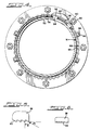
- Figure 2 is a cross-sectional end view of the first embodiment of the restrained push joint in accordance with the present invention;
- Figure 3 is a side cross-sectional view of a second embodiment of a restrained mechanical joint in accordance with the present invention;
- Figure 4 is an end cross-sectional view of the second embodiment of the restrained mechanical joint in accordance with the present invention;
- Figure 5 is a side view of a locking segment;
- Figure 6 is an end view of a locking segment; and
- Figure 7 is a perspective view of an embodiment of a retaining ring of the pipe joint of the present invention.
- Referring now to Figures 1 and 2 of the drawings, a restrained push joint is shown generally at 11. Spigot
end 12 of a first ductile iron pipe is received into thesocket end 10 of a second ductile iron pipe.Socket end 10 includes acircular indentation 16 into which gasket 14 is fit such that a liquid tight connection is made with theouter surface 18 offirst pipe 12 and withcircular indentation 16 ofsocket end 10 of the second pipe.Socket end 10 includes an inwardly extending circular wall 20 which forms a circular cutout section in the inner surface ofsocket end 10. A rectangular cutout opening 22 also extends around the entire inner surface ofsocket end 10. Asnap ring 24 is expanded by spring-like action to self hold within opening 22. - A
circular restraining ring 26 is fit in the cutout section ofsocket end 10 and is held in place by having its generally flatfront face 28 adjacent tosnap ring 24. Restrainingring 26 also includes an inclinedinner surface 30. -
Retainer ring 34 is comprised of a lockingsegment groove ring 36, and a series oflocking segments 38 separated byspacer elements 35 held within lockingsegment groove ring 36. It is also possible to fastenlocking segment 38 into lockingsegment groove ring 36 and thereby eliminate the need forspacer elements 35.Retainer ring 34 extends for slightly less than a 360 degree arc, having a spacing between itsends retainer ring 34 to be closed slightly in circumference.Locking segments 38 are made of steel, whereasspacer elements 35 are usually an elastomer such as rubber or a suitable plastic.Retainer ring 34 also includes three or moremetal clamp sections 31.Clamp section 31 is also comprised of anupturned section 42, each having a threadedopening 43.Clamp sections 31 are welded or, otherwise fastened to lockingsegment groove ring 36 which is a channel shaped member having an inner annular opening into whichlocking segments 38 are received.Locking segments 38 include protrudingteeth 40 which engageouter surface 18 offirst pipe 12. It is also possible to provide a retainer ring as two rings of slightly less than a 180 degree arc, each with two or more clamp sections. - A threaded bolt or similar threaded
fastener 44 extends through opening 43 inupturned section 42 and abutsflat front surface 28 ofcircular restraining ring 26. - Upon tightening of threaded
bolt 44 againstfront face 28 ofcircular restraining ring 26, the outer ortop surface 46 of lockingsegment groove ring 36 contacts the inclinedinner surface 30 ofcircular restraining ring 26.Top surface 46 is usually convex. This action forces teeth 40 oflocking segments 38 against and into a secure abutment withouter surface 18 ofspigot end 12 of the first pipe. - Note that threaded
fastener 44 and upturnedsection 42 ofclamp section 31 are present at sufficient locations about lockingsegment groove ring 36 in order to provide the necessary force to pushteeth 40 oflocking segment 38 intoouter surface 18 offirst pipe 12. Generally, three or four upturned sections per joint are adequate.Locking segments 38 are preferably of hardened steel or stainless steel. One preferred embodiment is type 431 stainless steel with a hardness of R49 (plus or minus four) Rockwell C. It is also preferred if theteeth 40 are formed by angles extending from the horizontal from 20 to 30 degrees. A preferred angle is 26 1/4 degrees. The other cutoutsection forming teeth 40 is perpendicular to the horizontal. Detailed views oflocking segment 38 are provided in Figures 5 and 6. - Referring to Figures 1 and 2, a typical assembly of a pipe joint in accordance with this embodiment of the present invention will now be explained.
Circular indentation 16 is lubricated with a standard pipe lubricant. Gasket 14 is inserted intocircular indentation 16 of thesocket end 10 of the second pipe.Retainer ring 34 andcircular restraining ring 26 are inserted into the circular cutout section ofsocket end 10 such thatcircular restraining ring 26 abuts circular wall 20.Snap ring 24 is installed into rectangular cutout opening 22. Threadedfasteners 44 are backed off and lockingsegment groove ring 36 is pushed back into socket until it abuts circular wall 20. - Lubrication is applied to exposed surface of gasket 14 and spigot end 18 of first pipe to facilitate assembly.
Spigot end 18 of first pipe is inserted past gasket 14 until it nears the back of socket. The desired joint deflection is set. Threadedfasteners 44 are then alternately tightened to specified torque to engageteeth 40 of lockingsegment 38 into contact withspigot surface 18. - As the fluid pressure is applied inside the pipe, the resultant separating force will cause locking
segment 38 to further grip intopipe spigot end 18 due to the angle of inclinedinner surface 30. Threadedfasteners 44 will no longer be in contact withsurface 28 ofcircular restraining ring 26 when the joint is loaded in this manner. - One advantage of this joint is that it can be deflected without sacrificing gasket tightness as the gasket is tightened prior to engaging gripping teeth. The joint also allows for subsequent joint movement as may be experienced with earth settlement without sacrificing joint tightness.
- Referring now to Figure 7, a perspective view of
retainer ring 34 is provided. Lockingsegment groove ring 36 is shown as comprising a channel shaped member receivinglocking segments 38 in an inner annular opening.Clamp sections 31 protrude from lockingsegment groove ring 36. - Referring now to Figures 3 and 4, a second embodiment of the present invention is shown generally at 50 as a restrained mechanical pipe joint with a bolt locking arrangement. The
spigot end 52 of a first ductile iron pipe extends into thesocket end 54 of a second ductile iron pipe.Socket end 54 includes a rim section into whichgasket 58 is fitted.Socket end 54 also includes a laterally extendingflange 60 having bolt holes 62 therein. - A circular
gasket support ring 64 is adjacent to flange 60 ofsocket end 54 and includesbolt openings 66 there through.Gasket support ring 64 also includes an extendedinner section 68 which abutsgasket 58 around its entire circumference.Circular restraining ring 70 is of a generally square or rectangular cross-section with a flatfront surface 72, flatrear surface 76 but an inclinedinner surface 74.Circular restraining ring 70 also includesbolt hole openings 78. -
Bolt 80 has a T-type head 81 which fits against the rear surface offlange 60 ofsecond pipe 54.Bolt 80 extends throughbolt hole openings 62 in thesocket end 54 of the second pipe, bolt hole opening 66 ingasket support ring 64 and bolt hole opening 78 incircular restraining ring 70.Nut 82 is threaded on the end ofbolt 80 such thatnut 82 forces against flatfront surface 72 ofcircular restraining ring 70. By tighteningnut 82,circular restraining ring 70 is forced againstgasket support ring 64 and also pulls against extendingflange 60 ofsecond pipe 54. Accordingly,inner flange 68 ofgasket support ring 64 butts against and compressesgasket 58 to form a seal between the rim section of the socket end ofsecond pipe 54 and theouter surface 56 offirst pipe 52.Sufficient bolts 80 are provided about the circumference of restrainingring 70 to assure the adequate strength coupling ofcircular restraining ring 70 andgasket support ring 64 to socket end ofsecond pipe 54. For example, for a six inch (15.2cm) diameter pipe, six such bolts are adequate, and for a 24 inch (61.0cm) diameter pipe, sixteen such bolts are adequate. -
Retainer ring 91 is comprised of a lockingsegment groove ring 90 and a series of lockingsegments 92 separated byspacer elements 95 held within lockingsegment groove ring 90. It is also possible to fasten lockingsegments 92 into lockingsegment groove ring 90 and thereby eliminate the need forspacer elements 95.Retainer ring 91 extends for slightly less than a 360 degree arc, having a spacing between itsends retainer ring 91 to be closed slightly in circumference. Lockingsegments 92 are made of steel, whereasspacer elements 95 are usually an elastomer such as rubber or suitable plastics.Retainer ring 91 also includes three or moremetal clamp sections 93. Eachclamp section 93 is also comprised of anupturned section 96, each having a threadedopening 97.Clamp sections 93 are welded or otherwise fastened to lockingsegment groove ring 90 which is a channel shaped member having an inner annular opening into which lockingsegments 92 are received. Lockingsegments 92 includes protrudingteeth 94 which engageouter surface 56 ofspigot end 52 of first pipe. It is also possible to provide a retainer ring as two rings of slightly less than 180 degree arc, each with two or more clamp sections. - A threaded bolt or similar threaded
fastener 98 extends through opening 97 inupturned section 96 and abuts flatfront surface 72 ofcircular restraining ring 70. - Upon tightening of threaded
bolt 98 againstfront face 72 ofcircular restraining ring 70, the outer ortop surface 99 of lockingsegment groove ring 90 contacts the inclinedinner surface 74 ofcircular restraining ring 70 .Top surface 99 is usually convex. This action forcesteeth 94 of lockingsegment 92 against and into a secure abutment withouter surface 56 ofspigot end 52 of the first pipe. - Note that threaded
fastener 98 andupturned section 96 are present at sufficient locations about lockingsegment groove ring 90 in order to provide the necessary force to pushteeth 94 of lockingsegment 92 intoouter surface 56 offirst pipe 52. Generally, three or four upturned sections per joint are adequate. Lockingsegment 92 is preferably a hardened steel or stainless steel of a type as previously described. - Referring to Figures 3 and 4, a typical assembly of a pipe joint in accordance with this embodiment of the present invention will now be explained. Threaded
fasteners 98 ofretainer ring 91 are backed off to allow clearance between inclinedinner surface 74 andtop surface 99 of lockingsegment groove ring 90.Slide retainer ring 91 andcircular restraining ring 70 onto spigot end 52 of first pipe. Slide circulargasket support ring 64 ontospigot end 52, adjacent toretainer ring 91.Slide gasket 58 ontospigot end 52, adjacent to circulargasket support ring 64 and brush-coat with lubricant. Insert spigot end 52 of first pipe intosocket end 54 of second pipe until spigot nears back of socket. Pushgasket 58 into recess, assuring even seating. Slidegasket support ring 64 andretainer ring assembly 91 into position. Installbolts 80 and tightennuts 82 until hand tight. Lockingsegment groove ring 90 should abut front surface ofgasket support ring 64 for proper assembly. Set the joint deflection and alternately tighten thebolts 80 to specified torque to tighten gasket. Tighten threadedfasteners 98 to engageteeth 94 of lockingsegment 92 into contact withouter surface 56 ofspigot end 52. - As the fluid pressure is applied inside the pipe, the resultant separating force will cause locking
segments 92 to further grip intoouter surface 56 of firstpipe spigot end 56 due to the angle of inclinedinner surface 74. Threadedfasteners 98 will no longer be in contact withsurface 72 ofcircular restraining ring 70 when the joint is loaded in this manner. - This restrained joint works well with all standard mechanical joint bells. This joint also allows the joint to be deflected without sacrificing gasket tightness as gasket is tightened prior to engaging gripping teeth. This joint allows for subsequent joint movement as may be experienced with earth settlement without sacrificing joint tightness.
Claims (11)
- A pipe joint (11;50) for joining the spigot end (12;52) of a first pipe to the socket end (10;54) of a second pipe, said pipe joint comprising:
a retainer ring (34;99) having locking means (38;94) for engaging the spigot end of the first pipe;
a restraining ring (26;70) coupled to the socket end of the second pipe and extending around the spigot end of the first pipe in use, the restraining ring being arranged to be movable in the axial direction of said joint relative to the retainer ring and having an inclined surface (46;74) for cooperating with said retainer ring; and
urging means (31;44;93;98) for urging said locking means into engagement with said spigot end of the first pipe to thereby form said joint; characterized in that:
said urging means (31;44;93;98) applies a force in the axial direction of said joint towards the socket end (10;54) of the second pipe on said restraining ring (26;70) and applies a force in the axial direction of said joint away from the socket end (10;54) of the second pipe on said retainer ring (34;99), thereby to move the retainer ring (34;99) along said inclined surface (46;74), whereby cooperation therebetween forces said locking means (38;94) into engagement with said spigot end (12;52) of the first pipe. - A pipe joint as claimed in claim 1, wherein said socket end of said second pipe comprises a circular flange (20) into which said restraining ring (26) is received, the flange having a cut-out section (22) for receiving a snap ring (24) which is arranged to secure said restraining ring in the socket end of the second pipe.
- A pipe joint as claimed in claim 1, wherein said socket end of said second pipe comprises a circular flange (60) having a plurality of bolt holes (62), the restraining ring is provided with a plurality of bolt holes (78) and a plurality of bolts (80) are provided for coupling said restraining ring to said second pipe via said flange.
- A pipe joint as claimed in any preceding claim comprising a sealing gasket (14,58) arranged between the spigot and socket ends, said sealing gasket being arranged to be compressed in response to locking movement of the restraining ring so as to enhance its sealing engagement between the socket and spigot ends.
- A pipe joint as claimed in claims 3 and 4, wherein a gasket support ring (64) having a plurality of bolt holes (66) for receiving said bolts is arranged between said flange and said restraining ring, the gasket (58) is arranged between said flange and said gasket support ring and second urging means (80, 81, 82) are provided for urging said flange, said gasket support ring and said restraining ring toward each other such that the gasket is compressed to enhance the seal between the socket end of the second pipe and the outer surface of the spigot end of the first pipe.
- A pipe joint as claimed in claim 1 or 2, wherein: said socket end of said second pipe includes a circular flange (20) extending laterally inwardly, and a circular cutout section (22) extending about the inside surface of said socket end,
said restraining ring is circular and has a generally flat front surface (28) and is positioned within said socket end of said second pipe adjacent said circular flange (20),
a circular snap ring (24) is received in said circular cutout section of said socket end of said second pipe, with a portion of said circular snap ring extending inwardly to secure said circular restraining ring within said socket end of said second pipe,
and said retainer ring assembly (34) adjacent an outer surface of said first pipe, comprises a groove ring (36) having a plurality of locking segments (38),
each of said locking segments having protruding teeth (40), and
said groove ring (36) also has a top surface which engages the inclined inner surface (46) of said circular restraining ring. - A pipe joint as claimed in claim 1 or 3, wherein said socket end (54) of said second pipe includes a laterally extending flange (60) having a plurality of bolt holes (62).
said pipe joint comprises a gasket support ring (64) including a laterally extending flange having a plurality of bolt holes (66), said gasket support ring being adjacent said socket end flange, a circular restraining ring (70) having generally flat front (72) and rear surfaces (76) and an inclined inner surface (74), said circular restraining ring being positioned with the rear surface thereof contacting a front surface of the gasket support ring flange, said circular restraining ring having a plurality of bolt holes (78), and further comprising:
a plurality of bolts (80), each of which extend through aligned bolt holes in said second pipe flange, said gasket support ring flange and said circular restraining ring,
and a retainer ring assembly (99) adjacent an outer surface of said first pipe comprising a groove ring (90) having a plurality of locking segments (92),
each of said locking segments having protruding teeth (40),
said groove ring also having a top surface which engages the inclined inner surface of said circular restraining ring. - The pipe joint of claim 6 or 7 further including spacer elements (35;95), separating said locking segments (28;92), said spacer elements comprising elastomer sections that join a plurality of locking segments to form an arcuate assembly installed within said groove ring.
- The pipe joint of claim 6, 7 or 8 including clamp sections (31;93) protruding from said groove ring, each of said clamp sections having a threaded opening (43;97), and a threaded means (43;98) extending through said threaded opening in said clamp section, said threaded means contacting said circular restraining ring to force the top surface of said groove ring against the inclined inner surface of said circular restraining ring.
- The pipe joint of claim 9 wherein said threaded means extends through said threaded opening in said clamp section such that, upon turning said threaded means, an end of said threaded means is moved into contact with said circular restraining ring.
- A method of assembling a mechanical pipe joint (11) for joining a spigot end (12) of a first pipe to a socket end (10) of a second pipe comprising the steps of:
providing the socket end of said second pipe with a circular flange (20) extending laterally inwardly,
providing a circular restraining ring (26) having a generally flat front surface (22) and an inclined inner surface (46), and positioning said circular restraining ring adjacent said circular flange,
placing a retainer ring (34) assembly within said circular restraining ring, said retainer ring assembly comprising a groove ring (26) having a plurality of locking segments (38),
placing the spigot end (12) of said first pipe into said socket end (10) of said second pipe and into said retainer ring assembly,
and forcing said locking segments into engagement with the outer surface of said first pipe;
characterised in that
said circular restraining ring is positioned within said socket end of said second pipe adjacent said circular flange, and
each of said locking segments include protruding teeth (40),
and in that said method further comprises:
providing a circular cutout section (22) extending about the inside surface of said socket end,
placing a circular snap ring (24) in said circular cutout section (22) of said socket end of said second pipe, with a portion of said circular snap ring extending inwardly to secure said circular restraining ring (26) within said socket end of said second pipe, and in that the step of forcing said locking segments into engagement with the outer surface of said first pipe comprises a step of applying a force in the axial direction of said joint towards the socket of the second pipe on the restraining ring by means of the urging means and applying a force in the axial direction of said joint away from the socket end of the second pipe on the retainer ring by means of the urging means to engage the inclined inner surface (46) of said circular restraining ring with a top surface of said groove ring (26).
Applications Claiming Priority (2)
| Application Number | Priority Date | Filing Date | Title |
|---|---|---|---|
| US07/518,426 US5037144A (en) | 1990-05-02 | 1990-05-02 | Restrained pipe joint |
| US518426 | 1990-05-02 |
Publications (3)
| Publication Number | Publication Date |
|---|---|
| EP0455490A2 EP0455490A2 (en) | 1991-11-06 |
| EP0455490A3 EP0455490A3 (en) | 1992-03-04 |
| EP0455490B1 true EP0455490B1 (en) | 1995-09-27 |
Family
ID=24063880
Family Applications (1)
| Application Number | Title | Priority Date | Filing Date |
|---|---|---|---|
| EP91303984A Expired - Lifetime EP0455490B1 (en) | 1990-05-02 | 1991-05-02 | Restrained pipe joint |
Country Status (6)
| Country | Link |
|---|---|
| US (1) | US5037144A (en) |
| EP (1) | EP0455490B1 (en) |
| JP (1) | JPH0689868B2 (en) |
| BR (1) | BR9101747A (en) |
| CA (1) | CA2036785C (en) |
| DE (1) | DE69113315T2 (en) |
Cited By (1)
| Publication number | Priority date | Publication date | Assignee | Title |
|---|---|---|---|---|
| WO2018172922A1 (en) * | 2017-03-21 | 2018-09-27 | Jindal Saw Ltd | Positive lock system for restrained joints of ductile iron spun pipes and fittings |
Families Citing this family (32)
| Publication number | Priority date | Publication date | Assignee | Title |
|---|---|---|---|---|
| GB8830202D0 (en) * | 1988-12-23 | 1989-02-22 | Parkfield Group Plc | Pipe coupling |
| US5205356A (en) * | 1990-12-27 | 1993-04-27 | Abb Vetco Gray Inc. | Well starter head |
| US5197768B1 (en) * | 1991-10-10 | 1995-04-04 | American Cast Iron Pipe Co | Restrained joint having elastomer-backed locking segments |
| FR2683609B1 (en) * | 1991-11-07 | 1995-01-20 | Pont A Mousson | LOCKED GASKET FOR PIPES. |
| FR2692644B1 (en) * | 1992-06-23 | 1995-11-24 | St Mihiel Sa | CRAMPING AND SEALING DEVICE FOR PIPE CONNECTING FLANGES. |
| EP0722551B1 (en) * | 1993-09-24 | 1998-06-17 | Donaldson Company, Inc. | Joint and seal system for air transfer tubes |
| NL1002514C2 (en) * | 1996-03-04 | 1997-09-05 | Fischer Georg Waga Nv | Coupling device. |
| US5613714A (en) * | 1996-03-14 | 1997-03-25 | Kubota Corporation | Separation-preventive pipe joint |
| EP0841043A3 (en) * | 1996-11-06 | 2000-04-12 | Otto Bock Orthopädische Industrie Besitz- und Verwaltungs-Kommanditgesellschaft | Orthopaedic clamp connection |
| US6026803A (en) * | 1997-05-21 | 2000-02-22 | Protech Manufacturing, Inc. | Coupling with built-in gasket and mechanical locking device |
| US5863080A (en) * | 1997-06-17 | 1999-01-26 | Phillips Petroleum Company | Bell and spigot slip-joint assembly |
| NL1011520C2 (en) * | 1999-03-10 | 2000-09-12 | Wijnant Van Genderen | Pressure device for fixing or sealing bodies. |
| US7108289B1 (en) * | 2000-06-08 | 2006-09-19 | United States Pipe And Foundry Company, Llc | Restraining gasket for mechanical joints of pipes |
| US7104573B2 (en) * | 2000-06-08 | 2006-09-12 | United States Pipe And Foundy Company, Llc | Energized restraining gasket for mechanical joints of pipes |
| US6786517B2 (en) | 2001-11-05 | 2004-09-07 | Dennis D. Shumard | Concentric pipe joint restraint |
| US6688652B2 (en) * | 2001-12-12 | 2004-02-10 | U.S. Pipe And Foundry Company | Locking device and method for securing telescoped pipe |
| US6974160B2 (en) * | 2003-05-19 | 2005-12-13 | S&B Technical Products, Inc. | Self restraining gasket and pipe joint |
| US20040232698A1 (en) * | 2003-05-19 | 2004-11-25 | Jim Jones | Self restraining gasket and pipe joint |
| US7125054B2 (en) * | 2003-05-19 | 2006-10-24 | S & B Technical Products, Inc. | Self restraining gasket and pipe joint |
| US6945570B2 (en) * | 2003-05-19 | 2005-09-20 | S & B Technical Products, Inc. | Self restraining gasket and pipe joint |
| KR100776384B1 (en) * | 2003-09-25 | 2007-11-16 | 유나이티드 스테이츠 파이프 앤 화운더리 컴퍼니, 엘엘씨 | Centroidally Twistable Compression Ring for Pipe Joints |
| US7484775B2 (en) * | 2004-07-13 | 2009-02-03 | Harold Kennedy, Jr. | Pipe joint restraint |
| US20080157524A1 (en) * | 2005-06-10 | 2008-07-03 | Jim Jones | Self-restrained ductile iron fitting |
| US7328493B2 (en) * | 2005-06-10 | 2008-02-12 | S & B Technical Products, Inc. | Self restrained fitting for PVC and ductile iron pipe |
| US20110062700A1 (en) * | 2009-09-15 | 2011-03-17 | S & B Technical Products, Inc. | Pipe coupling and use thereof in joining molecularly oriented pipe |
| JP5549552B2 (en) * | 2010-11-12 | 2014-07-16 | 東京エレクトロン株式会社 | Method for assembling vacuum processing apparatus and vacuum processing apparatus |
| RU2472056C1 (en) * | 2011-06-17 | 2013-01-10 | Открытое акционерное общество "Липецкий металлургический завод "Свободный сокол" (ОАО "ЛМЗ "Свободный сокол") | Pipeline connection |
| US9279325B2 (en) | 2012-11-08 | 2016-03-08 | General Electric Company | Turbomachine wheel assembly having slotted flanges |
| US20190219207A1 (en) | 2018-01-16 | 2019-07-18 | Rain Bird Corporation | Push To Connect Coupling |
| US11204114B2 (en) | 2019-11-22 | 2021-12-21 | Trinity Bay Equipment Holdings, LLC | Reusable pipe fitting systems and methods |
| JP7745516B2 (en) * | 2022-06-28 | 2025-09-29 | 株式会社クボタ | Ring body and pipe joining method using ring body |
| US12345359B2 (en) | 2022-10-12 | 2025-07-01 | Rain Bird Corporation | Tube coupling |
Family Cites Families (10)
| Publication number | Priority date | Publication date | Assignee | Title |
|---|---|---|---|---|
| US2538683A (en) * | 1948-01-31 | 1951-01-16 | Guiler Cameron | Fluid seal |
| US4186950A (en) * | 1977-09-14 | 1980-02-05 | Comex Marine Services, Inc. | Coupling apparatus |
| DE2918589A1 (en) * | 1978-05-18 | 1979-11-22 | Scheepswerf Stapel Bv | QUICK COUPLING BALL JOINT |
| US4428604A (en) * | 1981-03-12 | 1984-01-31 | American Cast Iron Pipe Company | Restrained pipe joint and associated snap-ring |
| JPS5853984U (en) * | 1981-09-30 | 1983-04-12 | 株式会社クボタ | Pull-out prevention device for pipe fittings |
| US4506919A (en) * | 1983-01-03 | 1985-03-26 | Amsted Industries Incorporated | Restrained mechanical pipe joint |
| US4552385A (en) * | 1983-01-03 | 1985-11-12 | Amsted Industries Incorporated | Boltless restrained pipe joint |
| CA1264342A (en) * | 1984-09-07 | 1990-01-09 | Kubota, Ltd. | Separation preventive pipe joint |
| US4712813A (en) * | 1986-10-28 | 1987-12-15 | Perfection Corporation | Coupling apparatus |
| US4867488A (en) * | 1987-08-13 | 1989-09-19 | United States Pipe And Foundry Company | Restrained joint with gripper gland |
-
1990
- 1990-05-02 US US07/518,426 patent/US5037144A/en not_active Expired - Lifetime
-
1991
- 1991-02-21 CA CA002036785A patent/CA2036785C/en not_active Expired - Fee Related
- 1991-04-30 BR BR919101747A patent/BR9101747A/en not_active IP Right Cessation
- 1991-05-02 EP EP91303984A patent/EP0455490B1/en not_active Expired - Lifetime
- 1991-05-02 DE DE69113315T patent/DE69113315T2/en not_active Expired - Fee Related
- 1991-05-02 JP JP3128194A patent/JPH0689868B2/en not_active Expired - Lifetime
Cited By (1)
| Publication number | Priority date | Publication date | Assignee | Title |
|---|---|---|---|---|
| WO2018172922A1 (en) * | 2017-03-21 | 2018-09-27 | Jindal Saw Ltd | Positive lock system for restrained joints of ductile iron spun pipes and fittings |
Also Published As
| Publication number | Publication date |
|---|---|
| EP0455490A2 (en) | 1991-11-06 |
| JPH0689868B2 (en) | 1994-11-14 |
| DE69113315T2 (en) | 1996-03-07 |
| EP0455490A3 (en) | 1992-03-04 |
| CA2036785A1 (en) | 1991-11-03 |
| US5037144A (en) | 1991-08-06 |
| CA2036785C (en) | 1996-08-13 |
| DE69113315D1 (en) | 1995-11-02 |
| BR9101747A (en) | 1991-12-10 |
| JPH04228991A (en) | 1992-08-18 |
Similar Documents
| Publication | Publication Date | Title |
|---|---|---|
| CA2036785C (en) | Restrained pipe joint | |
| AU2018267610B2 (en) | Coupling having tabbed retainer | |
| EP0412642B1 (en) | Rigid or flexible coupling for pipes | |
| US7341288B2 (en) | Restrained sleeve pipe coupling | |
| US5509699A (en) | Mechanical joint pipe adapter with inserted flexible spline | |
| US4643466A (en) | Pipe joint assembly with snap ring and associated method | |
| US7004511B2 (en) | Pipe coupling device | |
| US5496073A (en) | Disengagement tool for use with a pipe joint assembly | |
| US5328215A (en) | Pipe joint assembly | |
| US4486036A (en) | Reusable coupling | |
| KR101244771B1 (en) | Deformable mechanical pipe coupling | |
| WO1995033948A9 (en) | Mechanical joint pipe adapter | |
| MXPA02003910A (en) | Apparatus for connecting tubular bodies. | |
| US4524505A (en) | Method of assembling a pipe joint | |
| US5282654A (en) | Pipe coupling sleeve | |
| JP2001165366A (en) | Pipe fittings | |
| US20020163193A1 (en) | Pipe coupling | |
| EP0485076A1 (en) | Fitting | |
| US4486035A (en) | Reusable coupling | |
| HU218236B (en) | Pipe connector | |
| US4711426A (en) | Flanged valve connectors | |
| US6015170A (en) | Coupling assembly | |
| US5360238A (en) | Pipe couplings | |
| US5842726A (en) | Preformed transition pipe coupling | |
| US4416575A (en) | Union nut |
Legal Events
| Date | Code | Title | Description |
|---|---|---|---|
| PUAI | Public reference made under article 153(3) epc to a published international application that has entered the european phase |
Free format text: ORIGINAL CODE: 0009012 |
|
| AK | Designated contracting states |
Kind code of ref document: A2 Designated state(s): CH DE FR GB LI |
|
| PUAL | Search report despatched |
Free format text: ORIGINAL CODE: 0009013 |
|
| RHK1 | Main classification (correction) |
Ipc: F16D 21/04 |
|
| AK | Designated contracting states |
Kind code of ref document: A3 Designated state(s): CH DE FR GB LI |
|
| 17P | Request for examination filed |
Effective date: 19920508 |
|
| 17Q | First examination report despatched |
Effective date: 19930827 |
|
| GRAA | (expected) grant |
Free format text: ORIGINAL CODE: 0009210 |
|
| AK | Designated contracting states |
Kind code of ref document: B1 Designated state(s): CH DE FR GB LI |
|
| REF | Corresponds to: |
Ref document number: 69113315 Country of ref document: DE Date of ref document: 19951102 |
|
| ET | Fr: translation filed | ||
| PLBE | No opposition filed within time limit |
Free format text: ORIGINAL CODE: 0009261 |
|
| STAA | Information on the status of an ep patent application or granted ep patent |
Free format text: STATUS: NO OPPOSITION FILED WITHIN TIME LIMIT |
|
| 26N | No opposition filed | ||
| REG | Reference to a national code |
Ref country code: GB Ref legal event code: 732E |
|
| REG | Reference to a national code |
Ref country code: GB Ref legal event code: IF02 |
|
| PGFP | Annual fee paid to national office [announced via postgrant information from national office to epo] |
Ref country code: FR Payment date: 20020417 Year of fee payment: 12 |
|
| PGFP | Annual fee paid to national office [announced via postgrant information from national office to epo] |
Ref country code: CH Payment date: 20020419 Year of fee payment: 12 |
|
| PGFP | Annual fee paid to national office [announced via postgrant information from national office to epo] |
Ref country code: GB Payment date: 20020424 Year of fee payment: 12 |
|
| PGFP | Annual fee paid to national office [announced via postgrant information from national office to epo] |
Ref country code: DE Payment date: 20020520 Year of fee payment: 12 |
|
| PG25 | Lapsed in a contracting state [announced via postgrant information from national office to epo] |
Ref country code: GB Free format text: LAPSE BECAUSE OF NON-PAYMENT OF DUE FEES Effective date: 20030502 |
|
| PG25 | Lapsed in a contracting state [announced via postgrant information from national office to epo] |
Ref country code: LI Free format text: LAPSE BECAUSE OF NON-PAYMENT OF DUE FEES Effective date: 20030531 Ref country code: CH Free format text: LAPSE BECAUSE OF NON-PAYMENT OF DUE FEES Effective date: 20030531 |
|
| PG25 | Lapsed in a contracting state [announced via postgrant information from national office to epo] |
Ref country code: DE Free format text: LAPSE BECAUSE OF NON-PAYMENT OF DUE FEES Effective date: 20031202 |
|
| GBPC | Gb: european patent ceased through non-payment of renewal fee |
Effective date: 20030502 |
|
| REG | Reference to a national code |
Ref country code: CH Ref legal event code: PL |
|
| PG25 | Lapsed in a contracting state [announced via postgrant information from national office to epo] |
Ref country code: FR Free format text: LAPSE BECAUSE OF NON-PAYMENT OF DUE FEES Effective date: 20040130 |
|
| REG | Reference to a national code |
Ref country code: FR Ref legal event code: ST |