EP0455369B1 - Spring contact twister probe for testing electrical printed circuit boards - Google Patents
Spring contact twister probe for testing electrical printed circuit boards Download PDFInfo
- Publication number
- EP0455369B1 EP0455369B1 EP91303317A EP91303317A EP0455369B1 EP 0455369 B1 EP0455369 B1 EP 0455369B1 EP 91303317 A EP91303317 A EP 91303317A EP 91303317 A EP91303317 A EP 91303317A EP 0455369 B1 EP0455369 B1 EP 0455369B1
- Authority
- EP
- European Patent Office
- Prior art keywords
- barrel
- plunger
- probe
- spring contact
- contact probe
- Prior art date
- Legal status (The legal status is an assumption and is not a legal conclusion. Google has not performed a legal analysis and makes no representation as to the accuracy of the status listed.)
- Expired - Lifetime
Links
- 239000000523 sample Substances 0.000 title claims description 118
- 241001589086 Bellapiscis medius Species 0.000 title claims description 31
- 238000012360 testing method Methods 0.000 title description 21
- 230000009471 action Effects 0.000 claims description 4
- 238000007790 scraping Methods 0.000 claims description 2
- 230000006835 compression Effects 0.000 description 9
- 238000007906 compression Methods 0.000 description 9
- 230000004907 flux Effects 0.000 description 5
- 239000000356 contaminant Substances 0.000 description 4
- 238000011109 contamination Methods 0.000 description 4
- 239000004922 lacquer Substances 0.000 description 4
- 230000033001 locomotion Effects 0.000 description 3
- 238000003754 machining Methods 0.000 description 3
- 239000011159 matrix material Substances 0.000 description 3
- 239000002904 solvent Substances 0.000 description 3
- 238000003491 array Methods 0.000 description 2
- 238000004519 manufacturing process Methods 0.000 description 2
- 239000002184 metal Substances 0.000 description 2
- 238000000034 method Methods 0.000 description 2
- 239000002245 particle Substances 0.000 description 2
- 239000003518 caustics Substances 0.000 description 1
- 238000004140 cleaning Methods 0.000 description 1
- 230000007613 environmental effect Effects 0.000 description 1
- 230000003090 exacerbative effect Effects 0.000 description 1
- 230000002452 interceptive effect Effects 0.000 description 1
- 230000007246 mechanism Effects 0.000 description 1
- 230000008569 process Effects 0.000 description 1
- 230000002035 prolonged effect Effects 0.000 description 1
- 238000009877 rendering Methods 0.000 description 1
- 230000000717 retained effect Effects 0.000 description 1
- 229910000679 solder Inorganic materials 0.000 description 1
- 239000000126 substance Substances 0.000 description 1
Images

Classifications
-
- H—ELECTRICITY
- H01—ELECTRIC ELEMENTS
- H01R—ELECTRICALLY-CONDUCTIVE CONNECTIONS; STRUCTURAL ASSOCIATIONS OF A PLURALITY OF MUTUALLY-INSULATED ELECTRICAL CONNECTING ELEMENTS; COUPLING DEVICES; CURRENT COLLECTORS
- H01R11/00—Individual connecting elements providing two or more spaced connecting locations for conductive members which are, or may be, thereby interconnected, e.g. end pieces for wires or cables supported by the wire or cable and having means for facilitating electrical connection to some other wire, terminal, or conductive member, blocks of binding posts
- H01R11/11—End pieces or tapping pieces for wires, supported by the wire and for facilitating electrical connection to some other wire, terminal or conductive member
- H01R11/18—End pieces terminating in a probe
-
- G—PHYSICS
- G01—MEASURING; TESTING
- G01R—MEASURING ELECTRIC VARIABLES; MEASURING MAGNETIC VARIABLES
- G01R1/00—Details of instruments or arrangements of the types included in groups G01R5/00 - G01R13/00 and G01R31/00
- G01R1/02—General constructional details
- G01R1/06—Measuring leads; Measuring probes
- G01R1/067—Measuring probes
- G01R1/06711—Probe needles; Cantilever beams; "Bump" contacts; Replaceable probe pins
- G01R1/06716—Elastic
- G01R1/06722—Spring-loaded
Definitions
- the present invention is directed to a twister probe for use in apparatus that test printed circuit boards. More particularly, the present invention is directed to a spring contact probe having a plunger that reciprocates in a barrel and rotates as it reciprocates and starts from IBM Technical Disclosure Bulletin Vol.15, No 1, June 1972.
- Spring contact probes are commonly used in testing printed circuit boards and other types of circuits that require a number of contact points to be checked for continuity or correct electrical signals. Such contact probes are received into probe receptacles that are typically fitted into apertures in a testing board. The entire board is moved toward and away from the testing subject by an electro-mechanical or pneumatic means. Typically, probes are mounted throughout the surface area of a testing board in rows and columns in high density arrays. A compression spring inside each probe forces the plunger against the printed circuit board.
- pin-point probe that will usually penetrate the layer of contaminants on a circuit board.
- One such "pin-point” probe is shown in US Patent No. 4,787,861.
- a probe pressed against the circuit board with sufficient force will penetrate the layers of contaminants and permit effective testing of the circuits on the board.
- the force that can be applied to a probe is constrained by the diameter of the plunger body and probe tip, and the diameter of the compression spring that urges the plunger body toward the printed circuit board. Only by making the probe tip small can sufficient pressure be exerted against the runner to ensure that the debris are penetrated by the probe tip. This, however, leads to the probe tips sticking into the circuit board or circuit board runners.
- One twisting probe has a barrel that is opened at both ends, a circumferential crimp near the probe tip end of the barrel and a plunger within the barrel.
- the plunger includes a probe tip end and a twisted end that projects through the rear of the barrel.
- the rear of the barrel has a square opening that the twisted plunger passes through, causing the plunger to rotate along its longitudinal axis as it reciprocates within the barrel.
- This probe is not known to the inventor and it could not be used in any standard printed circuit board testing apparatus because the portion of the plunger extending outwardly of the barrel would interfere with mounting the probe in a standard probe receptacle or socket.
- Another twister probe includes a barrel having an open front end and rear end, with the probe tip comprising a portion of the plunger, which is seated within the barrel and reciprocates therein.
- a compression spring urges the plunger outward from the barrel.
- the barrel includes a sleeve with a curved cam slot along its length.
- a small cylindrical pin is inserted into the plunger body perpendicular to the longitudinal axis of the plunger body. The pin acts as a cam follower that follows the curved cam surface of the slot in the sleeve, or the enlarged portion of the barrel.
- This style of probe suffers from significant drawbacks.
- the cam itself must be cut into the side wall of the barrel. These features lead to excessive manufacturing costs. Further, and more seriously, the cam slot can be easily contaminated by particles of lacquer, fluxes, and solder that are broken free of the printed circuit board during testing. In particular, even small amounts of flux that contact the upper exposed portion of the plunger in the cam slot can be carried into the interior of the barrel when the plunger reciprocates, and will corrode the inner portions of the probe sufficiently to produce intermittent open circuits, thus rendering the probe unreliable. Exacerbating these contamination problems, such probes are generally mounted below the subject circuit board, that is, with the probe tip pointing up. Thus, the debris loosened by the twisting probe tip falls down onto the probe itself.
- Webb U.S. Patent No. 3,458,851 accomplishes this rotation of the connector pin as it reciprocates within the housing by having an indented boss in the housing that rides in a helical groove along a portion of the connector pin shaft that is retained within the housing. There is only one indented boss, and only one helical groove. The camming action of the indented boss riding the helical groove causes the connector pin to rotate as it reciprocates.
- the rear of the tubular housing is closed and sealed.
- the front end of the tubular housing is open to allow the connector pin to extend beyond the housing and to allow air to enter and to escape from the housing as the connector pin reciprocates therein.
- An inwardly extending circumferential flange at the front edge of the tubular housing forms a stop that prevents a larger diameter connector pin portion from moving outside the housing.
- Webb U.S. Patent No. 3,458,851 might appear to provide a good solution to the problem at hand, namely, testing printed circuit boards. This is not the case.
- Webb U.S. Patent No. 3,458,851 includes a number of characteristics that make it unsuitable for testing printed circuit boards and that would cause serious difficulties if it were adapted for such use by, e.g. replacing the rounded tip of the connector pin with a cutting tip.
- testing printed circuit boards requires many hundreds of thousands of probes. In addition, they must be manufactured to very close tolerances to perform correctly. Consequently, the cost of manufacture, the simplicity of design, and the ease of reproducing the probe accurately are all vital considerations.
- Webb U.S. Patent No. 3,458,851 includes a helical groove in the connector pin shaft. It is difficult and expensive to cut or otherwise form grooves in shafts and it is not economically viable in this use.
- pointing accuracy of the probe is of the utmost importance in testing printed circuit boards.
- the testing apparatus is programmed to expect a specific signal from each probe in the densely packed arrays. Each probe is aimed at a precise, specific point on the printed circuit board. If one or more probes do not hit their targets when the circuit board is tested, the test results may be wrong. Circuit board runners are sometimes very narrow and easily missed. Incorrectly aimed or pointed probes may miss the test pad altogether. Probes that do not hit their targets can incorrectly indicate the presence of either an open or closed circuit.
- the strike point of a probe used for testing printed circuit boards needs to be within about seventy-six ten-thousandths of a centimeter (0.0076 cm, 0.0030 inch) of the target.
- the pivot bearing includes two small facing bearing surfaces at the back end of the connector pin, which are largely responsible for aiming the connector pin and these bearing surfaces offer little contact area and are restricted to only the end of the connector pin. Consequently, these bearing surfaces do not provide a high degree of pointing accuracy.
- a twisting electrical spring contact probe comprising a barrel, an internal spring means and a rotatable plunger, the barrel having a spring seating end and an open end with at least two opposed crimp means between said spring seating end and said open end; the spring means being located within said barrel; the plunger having a shaft reciprocally received within said barrel, the shaft including a twister portion with at least two helically opposed crests and a tip end for rotating with said plunger for providing a scraping action on a target; and said crimp means extending between said barrel and said shaft with one said crimp means bearing upon each said helical crest and urging rotation of said plunger as said plunger reciprocates relative to said barrel by providing that said crimp means are spaced from and located between said spring seating end and said open end of said barrel; and said twister portion is contained wholly within said barrel in extended and retracted positions.
- the crimps further comprise four V-shaped crimps equally spaced about the circumference of the barrel throughout a single cross section of the barrel.
- the plunger further includes a probe tip end and a contact stem end.
- the contact stem end of the plunger has a larger cross section than the cross section of the crimped portion of the barrel, so that the plunger will not become disengaged from the barrel.
- the compression spring is pressed onto the contact stem of the plunger.
- the plunger further comprises a tail section, a shank section, a twister section or portion between the tail section and the shank section.
- the plunger is made from a single piece of metal by machining or another process.
- the plunger includes a probe tip that is sharpened to a point, such as a chisel point having three sloping faces of equal size and equal angular spacing about the outer perimeter of the probe tip end.
- the barrel is cylindrical
- the compression spring is cylindrical
- the plunger is substantially cylindrical.
- the twister section of the plunger further comprises a square rod having a longitudinal axis, with the square rod portion being twisted along the longitudinal axis, or a rod having a shape that would be generated by such twisting. More particularly, the square rod is twisted by 90° over a distance of 0.635 cm (0.25 inches) or assumes the shape of such a rod.
- a spring contact twister probe 10 having a barrel 12 with a closed spring seating end 14 and an open end 16.
- the spring seating end 14 of the barrel 12 may also be open and may include a small inward projecting circumferential flange 15 to retain the compression spring 28, as illustrated in the alternative embodiment in Figure 9.
- the flange 15 is flat and extends inward from the circumferential edge of the length of the barrel 12 and perpendicular to the cylindrical surface of the barrel 12. Alternatively, the flange 15 may be recessed into the barrel 12.
- the tip of the rounded spring seating end 14 of the barrel 12 includes a small aperture 17 for alternatively expelling air from the barrel 12 when the plunger 20 is pressed into the barrel 12 and for admitting air into the barrel 12 while the plunger 20 is returning to its fully extended position of repose, which is shown in Figures 1 and 2.
- the fit between the barrel 12 and the plunger 20 is close enough that an air bleed hole of some type is required for proper operation of the probe 10.
- the barrel 12 may be machined, but preferably is drawn.
- the barrel 12 further includes four crimps 18, three of which are visible in Figure 1. The crimps 18 are located in a position intermediate of, that is, between, the spring seating end 14 and the open end 16.
- the spring contact probe 10 further includes the plunger 20 having a probe tip 22 that terminates in a point 24.
- the point 24 comprises three chiselled faces 26 two of which are visible in Figure 1.
- the faces 26 are of the same dimensions and are equally spaced about the circumference of the probe tip 22. Other styles of probe tips are easily designed.
- the barrel 12 is cylindrical.
- the plunger is essentially cylindrical and is preferably made from a single round rod, but comprises a number of different shaped sections, as will be discussed below.
- the compression spring 28 ( Figure 2) is also substantially cylindrical.
- FIG. 2 there is shown an environmental view of the spring contact twister probes 10 as they are arrayed for use.
- the spring contact twister probes 10 are seated in suitable receptacles 30 having contact electrical leads 32 exiting from the rear end 34 of the receptacles 30.
- the leads 32 conduct electrical currents to suitable test apparatus (not shown).
- the spring contact twister probes 10 are generally disposed in a high density matrix 31 having 20 probes per 2,54 cm (linear inch) or more.
- the probe tip 22 is brought into engagement with a printed circuit board (not shown) to be tested and the compression spring 28 exerts a continuous outward force on the probe tip 22, urging the probe tip 22 against the circuit board, leading to a good mechanical and electrical connection between the point 24 and the printed circuit board, when the printed circuit board is clean.
- the spring contact twister probe 10 herein disclosed twists like a drill bit to burrow through the debris to the conducting runners of the circuit board. As illustrated in Figure 2, the probe tips 22 typically point up, causing any debris loosened by the twisting probe to fall onto the probes and the matrix board. This nearly universal orientation of probes used in testing circuit boards permits them to be contaminated readily, interfering with the mechanical reciprocating operation and electrical conductivity of most probes.
- the plunger 20 is shown fully extended and clearly includes a probe section 36 that is cylindrical and further comprises the probe tip 22 developed from a cylindrical shape and the shaft or shank 38 which is of smaller diameter than the probe tip 22. Also included is a tail section 40 having a contact stem 42 onto which the compression spring 28 is pressed. Between the tail section 40 and the shaft 38 or probe section 36, lies the twister section 44.
- the twister section includes at least two helical crests 46 that are parallel to one another and are opposed to one another. That is, they are 180° apart about the perimeter of circumference of the plunger 20 at all points.
- each helical crest is engaged by one crimp 18 with the two crimps 18 being opposite one another, or opposed.
- This arrangement leads to equal lateral forces being exerted on the plunger 20, primarily perpendicular to the longitudinal axis of the plunger 20, which are translated into rotational forces when the plunger 20 reciprocates within the barrel 12. Any residual lateral forces that are not so translated are cancelled out, thereby reducing or eliminating any tendency of the plunger 20 to wobble as it reciprocates within the barrel 12.
- the helical crests 46 are preferably formed conceptually by beginning with a square rod having a longitudinal axis along its longitudinal centerline and twisting the rod about the longitudinal axis by 90° over a distance of 0.635 cm (0.25 inches) leading to a twister probe that rotates the probe tip 22 through 90° of rotation about its longitudinal axis during the full length of travel of the plunger 20 relative to the barrel 12. This shape can readily be cut into a round rod by well known machining techniques.
- the four crimps 18 form portions of the sides of a square when viewed as a cross section of the barrel 12.
- the portions of the square sides have substantially the same dimension as the distance from crest-to-crest across any given cross section of the twister section.
- the helical crests 46 cannot pass between the flat surfaces or lands 48 formed by the crimps 18. Accordingly, the crests 46 can only pass through the spaces 50 between adjacent crimps 18.
- One helical crest 46 passes continuously between each of the gaps formed between adjacent crimps 18. For the helical crests 46 to remain in the four gaps or spaces 50, naturally, the plunger 20 must rotate along its longitudinal axis.
- the plunger 20 is shown in a fully extended position.
- the plunger 20 is shown is an intermediate position between being fully extended and fully retracted.
- the plunger 20 is shown in the fully retracted position.
- the plunger 20 is preferably made from a single piece of metal by machining or the like.
- the design of the spring contact twister probe 10 allows for many different sizes and styles of probe tips 22.
- the tolerances between the plunger 20 and the open end 16 of the barrel 12 are such that debris cannot readily enter the interior chamber of the barrel 12.
- the twister section 44 of the plunger 20 is wholly retained inside the barrel 12 at all times, permitting the use of a cylindrical probe section 36 of the plunger 20 to mate with the cylindrical barrel 12, which allows for tighter tolerances and prevents the sharp-edged helical crests 46 from extending beyond the open end 16 of the barrel 12, which would make contamination of the spring contact twister probe 10 easier. All twisting mechanisms are well within the barrel. Further, the crimps 18 are remote from the open end 16 of the barrel 12, further reducing the threat of contamination. In the preferred embodiment illustrated herein, referring to Figure 7, it is shown that the shaft portion 38 changes from a cylindrical shaft section 38 to square cross section portion 52 prior to assuming a larger cylindrical section comprising the probe tip 22.
- the spring contact twister probe 10 fits a standard receptacle and may be used interchangeably in any circuit board tester using industry standard size apertures.
- the force with which the probe tip 22 contacts the circuit board, as well as the sweep angle, that is, the degree of rotation of the plunger 20 about its longitudinal axis, can be customized to fit individual circumstances. Different head styles on the probe tip 22 can further increase the ability of the spring contact twister probe 10 to penetrate debris.
Landscapes
- Physics & Mathematics (AREA)
- General Physics & Mathematics (AREA)
- Measuring Leads Or Probes (AREA)
Description
- The present invention is directed to a twister probe for use in apparatus that test printed circuit boards. More particularly, the present invention is directed to a spring contact probe having a plunger that reciprocates in a barrel and rotates as it reciprocates and starts from IBM Technical Disclosure Bulletin Vol.15,
No 1, June 1972. - Spring contact probes are commonly used in testing printed circuit boards and other types of circuits that require a number of contact points to be checked for continuity or correct electrical signals. Such contact probes are received into probe receptacles that are typically fitted into apertures in a testing board. The entire board is moved toward and away from the testing subject by an electro-mechanical or pneumatic means. Typically, probes are mounted throughout the surface area of a testing board in rows and columns in high density arrays. A compression spring inside each probe forces the plunger against the printed circuit board.
- When printed circuit boards are made and after electrical components are soldered to them, the runners are dirty. They are covered with lacquers and highly corrosive fluxes. In the past, these contaminants have been washed from the printed circuit boards by various solvents prior to testing them for proper electrical conductivity. Many of the solvents used for cleaning printed circuit boards have been restricted or banned or are being phased out under federal government regulations designed to improve the general environment. One such family of solvents, is for example, fluorocarbons. As a consequence, circuit boards are increasingly being tested without being cleaned. Many of the currently used testing probes will not reliably penetrate the debris on the circuit boards and make good mechanical and electrical contact with the circuit board runners and consequently lead to erroneous indications of open circuits.
- To overcome this difficulty, some manufacturers have produced a so called "pin-point" probe that will usually penetrate the layer of contaminants on a circuit board. One such "pin-point" probe is shown in US Patent No. 4,787,861. Unfortunately, however, such pin-point probes sometimes stick into the runners and will not retract when the test is completed. In theory, a probe pressed against the circuit board with sufficient force will penetrate the layers of contaminants and permit effective testing of the circuits on the board. In practice, however, the force that can be applied to a probe is constrained by the diameter of the plunger body and probe tip, and the diameter of the compression spring that urges the plunger body toward the printed circuit board. Only by making the probe tip small can sufficient pressure be exerted against the runner to ensure that the debris are penetrated by the probe tip. This, however, leads to the probe tips sticking into the circuit board or circuit board runners.
- Other efforts to permit testing of dirty circuit boards in hostile environments contaminated with free particles and corrosive chemicals have been developed. They employ some means for ensuring that the plunger of the probe will twist or rotate as the plunger reciprocates within the barrel. In such probes, the probe tip acts like a drill bit, turning or rotating along its longitudinal axis as it contacts the printed circuit board. The rotating or twisting motion of the sharp point of the probe enables the probe to cut through most debris resulting from the manufacture of the circuit board.
- One twisting probe has a barrel that is opened at both ends, a circumferential crimp near the probe tip end of the barrel and a plunger within the barrel. The plunger includes a probe tip end and a twisted end that projects through the rear of the barrel. The rear of the barrel has a square opening that the twisted plunger passes through, causing the plunger to rotate along its longitudinal axis as it reciprocates within the barrel. The use of this probe is not known to the inventor and it could not be used in any standard printed circuit board testing apparatus because the portion of the plunger extending outwardly of the barrel would interfere with mounting the probe in a standard probe receptacle or socket.
- Another twister probe includes a barrel having an open front end and rear end, with the probe tip comprising a portion of the plunger, which is seated within the barrel and reciprocates therein. A compression spring urges the plunger outward from the barrel. The barrel includes a sleeve with a curved cam slot along its length. A small cylindrical pin is inserted into the plunger body perpendicular to the longitudinal axis of the plunger body. The pin acts as a cam follower that follows the curved cam surface of the slot in the sleeve, or the enlarged portion of the barrel. This style of probe suffers from significant drawbacks. First, it includes four parts, namely the barrel, the probe, the spring and the cam follower. In addition, the cam itself must be cut into the side wall of the barrel. These features lead to excessive manufacturing costs. Further, and more seriously, the cam slot can be easily contaminated by particles of lacquer, fluxes, and solder that are broken free of the printed circuit board during testing. In particular, even small amounts of flux that contact the upper exposed portion of the plunger in the cam slot can be carried into the interior of the barrel when the plunger reciprocates, and will corrode the inner portions of the probe sufficiently to produce intermittent open circuits, thus rendering the probe unreliable. Exacerbating these contamination problems, such probes are generally mounted below the subject circuit board, that is, with the probe tip pointing up. Thus, the debris loosened by the twisting probe tip falls down onto the probe itself.
- An effort to overcome a related problem is found in U.S. Patent No. 3,458,851 issued to Webb as Administrator of the National Aeronautics and Space Administration on July 29, 1969 for Electrical Connector Pin With Wiping Action. Webb U.S. patent No. 3,458,851 discloses an electrical connector pin having a spring biased cylindrical connector pin to be received within a female socket. Foreign matter in the socket may prevent good electrical contact with a connector pin that is inserted straight into the socket. Webb U.S. Patent No. 3,458,851 reduces the likelihood of this occurrence by causing the connector pin to rotate as it is extended from its housing by the biasing spring, causing the connector pin to wipe the side wall of the cylindrical socket as the connector pin enters the socket.
- Webb U.S. Patent No. 3,458,851 accomplishes this rotation of the connector pin as it reciprocates within the housing by having an indented boss in the housing that rides in a helical groove along a portion of the connector pin shaft that is retained within the housing. There is only one indented boss, and only one helical groove. The camming action of the indented boss riding the helical groove causes the connector pin to rotate as it reciprocates. The rear of the tubular housing is closed and sealed. The front end of the tubular housing is open to allow the connector pin to extend beyond the housing and to allow air to enter and to escape from the housing as the connector pin reciprocates therein. An inwardly extending circumferential flange at the front edge of the tubular housing forms a stop that prevents a larger diameter connector pin portion from moving outside the housing.
- Webb U.S. Patent No. 3,458,851 might appear to provide a good solution to the problem at hand, namely, testing printed circuit boards. This is not the case. Webb U.S. Patent No. 3,458,851 includes a number of characteristics that make it unsuitable for testing printed circuit boards and that would cause serious difficulties if it were adapted for such use by, e.g. replacing the rounded tip of the connector pin with a cutting tip. First, testing printed circuit boards requires many hundreds of thousands of probes. In addition, they must be manufactured to very close tolerances to perform correctly. Consequently, the cost of manufacture, the simplicity of design, and the ease of reproducing the probe accurately are all vital considerations.
- Webb U.S. Patent No. 3,458,851 includes a helical groove in the connector pin shaft. It is difficult and expensive to cut or otherwise form grooves in shafts and it is not economically viable in this use.
- Second, pointing accuracy of the probe is of the utmost importance in testing printed circuit boards. The testing apparatus is programmed to expect a specific signal from each probe in the densely packed arrays. Each probe is aimed at a precise, specific point on the printed circuit board. If one or more probes do not hit their targets when the circuit board is tested, the test results may be wrong. Circuit board runners are sometimes very narrow and easily missed. Incorrectly aimed or pointed probes may miss the test pad altogether. Probes that do not hit their targets can incorrectly indicate the presence of either an open or closed circuit. The strike point of a probe used for testing printed circuit boards needs to be within about seventy-six ten-thousandths of a centimeter (0.0076 cm, 0.0030 inch) of the target. This degree of accuracy is not achieved by the Webb U.S. Patent No. 3,458,851 connector pin, which relies on a pilot socket portion and a pilot pin tip having a smaller diameter than the connecting portion of the connector pin to locate the connector pin the receiving socket. The use of a single indented boss riding in a single helical groove causes the connector pin to wobble as it reciprocates within the housing as the forces exerted on the connector probe by the indented boss riding in the groove are essentially perpendicular to the axis of the connector pin and, after the limit of the sideways movement of the connector pin is reached, are translated into rotational forces. Because the lateral or sideways force exerted on the connector pin is essentially constant in both magnitude and direction and the connector pin reciprocates within the housing, the connector pin can be expected to wobble throughout its entire reciprocation cycle.
- Further, the pivot bearing includes two small facing bearing surfaces at the back end of the connector pin, which are largely responsible for aiming the connector pin and these bearing surfaces offer little contact area and are restricted to only the end of the connector pin. Consequently, these bearing surfaces do not provide a high degree of pointing accuracy.
- Also demonstrative of the inadequate pointing accuracy of the connector pin of Webb U.S. Patent No. 3,458,851 is the fact that the rear of the housing is sealed, which requires the air that must enter and escape from the interior of the housing must pass through the gap between the connector pin and the housing. This structure is wholly inadequate for the task at hand because a gap large enough to admit the necessary volume of air will also admit the various contaminants of dirty printed circuit boards.
- Another prior spring contact electrical probe is disclosed by IBM Technical Disclosure Bulletin Vol. 15, No. 1, June 1972. This probe is essentially a drill shank contained within a barrel and urged outwardly by a coil spring. The end of the barrel is shaped to conform to the cross sectional shape of the drill bit with the end result that the drill shank rotates as it extends from the barrel.
- Accordingly, there is a need for an electrical spring contact probe that can reliably penetrate the dirt and debris that typically accompany unwashed printed circuit boards and that will not be subject to contamination from that debris.
- Accordingly, it is a primary object of the present invention to provide an electrical spring contact probe that can reliably and repeatedly penetrate the lacquers, fluxes and other debris on unwashed printed circuit boards during testing.
- It is a further object of the present invention to provide a spring contact electrical probe that has a plunger that will continue to operate and reciprocate within the barrel reliably despite prolonged use in hostile and dirty environments.
- It is a further object of the present invention to provide a spring contact electrical probe that is not prone to drawing corrosive substances into the barrel as the plunger reciprocates.
- These and other objects of the present invention are achieved in a twisting electrical spring contact probe comprising a barrel, an internal spring means and a rotatable plunger, the barrel having a spring seating end and an open end with at least two opposed crimp means between said spring seating end and said open end; the spring means being located within said barrel; the plunger having a shaft reciprocally received within said barrel, the shaft including a twister portion with at least two helically opposed crests and a tip end for rotating with said plunger for providing a scraping action on a target; and said crimp means extending between said barrel and said shaft with one said crimp means bearing upon each said helical crest and urging rotation of said plunger as said plunger reciprocates relative to said barrel by providing that said crimp means are spaced from and located between said spring seating end and said open end of said barrel; and said twister portion is contained wholly within said barrel in extended and retracted positions.
- The crimps further comprise four V-shaped crimps equally spaced about the circumference of the barrel throughout a single cross section of the barrel. The plunger further includes a probe tip end and a contact stem end. The contact stem end of the plunger has a larger cross section than the cross section of the crimped portion of the barrel, so that the plunger will not become disengaged from the barrel. The compression spring is pressed onto the contact stem of the plunger. The plunger further comprises a tail section, a shank section, a twister section or portion between the tail section and the shank section. In the preferred embodiment the plunger is made from a single piece of metal by machining or another process.
- The plunger includes a probe tip that is sharpened to a point, such as a chisel point having three sloping faces of equal size and equal angular spacing about the outer perimeter of the probe tip end. In the preferred embodiment, the barrel is cylindrical, the compression spring is cylindrical, and the plunger is substantially cylindrical.
- The twister section of the plunger further comprises a square rod having a longitudinal axis, with the square rod portion being twisted along the longitudinal axis, or a rod having a shape that would be generated by such twisting. More particularly, the square rod is twisted by 90° over a distance of 0.635 cm (0.25 inches) or assumes the shape of such a rod.
- Other advantages of this invention will become apparent from the following description taken in connection with the accompanying drawings, wherein is set forth by way of illustration and example, an embodiment of this invention.
-
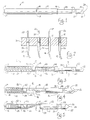
- Figure 1 is a side elevation of the spring contact twister probe according to the present invention;
- Figure 2 is a side elevation partially in section of a number of spring contact twister probes seated in receptacles in a matrix board;
- Figure 3 is an elevation of the spring contact twister probe of Figure 1 partially in section illustrating the probe in the fully extended position;
- Figure 4 is an elevation partially in section illustrating the spring contact twister probe with the probe tip in an intermediate position;
- Figure 5 is an elevation of the probe of Figure 1 with the probe tip in the fully retracted position;
- Figure 6 is a cross sectional view taken along lines 6-6 of Figure 3;
- Figure 7 is a cross sectional view taken along lines 7-7 of Figure 3;
- Figure 8 is a side elevation of the twister portion or section of the plunger;
- Figure 9 is an end elevation of an alternative embodiment of the barrel of the spring contact twister probe illustrating the spring seating end of the barrel.
- As required by the statutes and case law, a detailed embodiment of the present invention is disclosed herein. It is, however, to be understood that the disclosed embodiment is merely exemplary of the invention, which may be embodied in various forms. Therefore, specific structural and functional details disclosed herein are not to be interpreted as limiting, but merely as a basis for the claims and as a representative basis for teaching one skilled in the art to variously employ the present invention in virtually any appropriately detailed structures, within the scope of the Claims.
- Referring to Figure 1, there is shown a spring
contact twister probe 10 having abarrel 12 with a closedspring seating end 14 and anopen end 16. Thespring seating end 14 of thebarrel 12 may also be open and may include a small inward projectingcircumferential flange 15 to retain thecompression spring 28, as illustrated in the alternative embodiment in Figure 9. Theflange 15 is flat and extends inward from the circumferential edge of the length of thebarrel 12 and perpendicular to the cylindrical surface of thebarrel 12. Alternatively, theflange 15 may be recessed into thebarrel 12. In the preferred embodiment, however, the tip of the roundedspring seating end 14 of thebarrel 12 includes asmall aperture 17 for alternatively expelling air from thebarrel 12 when theplunger 20 is pressed into thebarrel 12 and for admitting air into thebarrel 12 while theplunger 20 is returning to its fully extended position of repose, which is shown in Figures 1 and 2. The fit between thebarrel 12 and theplunger 20 is close enough that an air bleed hole of some type is required for proper operation of theprobe 10. Thebarrel 12 may be machined, but preferably is drawn. Thebarrel 12 further includes fourcrimps 18, three of which are visible in Figure 1. Thecrimps 18 are located in a position intermediate of, that is, between, thespring seating end 14 and theopen end 16. All four of thecrimps 18 are spaced evenly about the circumference of the barrel along one cross section, that is, the crimps are 90° apart on centers and are all aligned. Thespring contact probe 10 further includes theplunger 20 having aprobe tip 22 that terminates in apoint 24. Thepoint 24 comprises threechiselled faces 26 two of which are visible in Figure 1. The faces 26 are of the same dimensions and are equally spaced about the circumference of theprobe tip 22. Other styles of probe tips are easily designed. - The
barrel 12 is cylindrical. The plunger is essentially cylindrical and is preferably made from a single round rod, but comprises a number of different shaped sections, as will be discussed below. The compression spring 28 (Figure 2) is also substantially cylindrical. - Referring to Figure 2, there is shown an environmental view of the spring contact twister probes 10 as they are arrayed for use. The spring contact twister probes 10 are seated in
suitable receptacles 30 having contact electrical leads 32 exiting from therear end 34 of thereceptacles 30. The leads 32 conduct electrical currents to suitable test apparatus (not shown). The spring contact twister probes 10 are generally disposed in ahigh density matrix 31 having 20 probes per 2,54 cm (linear inch) or more. In use, theprobe tip 22 is brought into engagement with a printed circuit board (not shown) to be tested and thecompression spring 28 exerts a continuous outward force on theprobe tip 22, urging theprobe tip 22 against the circuit board, leading to a good mechanical and electrical connection between thepoint 24 and the printed circuit board, when the printed circuit board is clean. When, however, the circuit boards are not clean, but retain lacquers and fluxes, it is considerably more difficult to secure a sound mechanical and electrical connection. The springcontact twister probe 10 herein disclosed twists like a drill bit to burrow through the debris to the conducting runners of the circuit board. As illustrated in Figure 2, theprobe tips 22 typically point up, causing any debris loosened by the twisting probe to fall onto the probes and the matrix board. This nearly universal orientation of probes used in testing circuit boards permits them to be contaminated readily, interfering with the mechanical reciprocating operation and electrical conductivity of most probes. - Referring now to Figure 3, the
plunger 20 is shown fully extended and clearly includes aprobe section 36 that is cylindrical and further comprises theprobe tip 22 developed from a cylindrical shape and the shaft orshank 38 which is of smaller diameter than theprobe tip 22. Also included is atail section 40 having acontact stem 42 onto which thecompression spring 28 is pressed.
Between thetail section 40 and theshaft 38 orprobe section 36, lies thetwister section 44. - The twister section includes at least two
helical crests 46 that are parallel to one another and are opposed to one another. That is, they are 180° apart about the perimeter of circumference of theplunger 20 at all points. In this two crest embodiment, each helical crest is engaged by onecrimp 18 with the twocrimps 18 being opposite one another, or opposed. This arrangement leads to equal lateral forces being exerted on theplunger 20, primarily perpendicular to the longitudinal axis of theplunger 20, which are translated into rotational forces when theplunger 20 reciprocates within thebarrel 12. Any residual lateral forces that are not so translated are cancelled out, thereby reducing or eliminating any tendency of theplunger 20 to wobble as it reciprocates within thebarrel 12. - In the preferred embodiment, there are four
helical crests 46. The helical crests 46 are preferably formed conceptually by beginning with a square rod having a longitudinal axis along its longitudinal centerline and twisting the rod about the longitudinal axis by 90° over a distance of 0.635 cm (0.25 inches) leading to a twister probe that rotates theprobe tip 22 through 90° of rotation about its longitudinal axis during the full length of travel of theplunger 20 relative to thebarrel 12. This shape can readily be cut into a round rod by well known machining techniques. - Referring to Figure 6, the four
crimps 18 form portions of the sides of a square when viewed as a cross section of thebarrel 12. The portions of the square sides have substantially the same dimension as the distance from crest-to-crest across any given cross section of the twister section. Thus, the helical crests 46 cannot pass between the flat surfaces or lands 48 formed by thecrimps 18. Accordingly, thecrests 46 can only pass through the spaces 50 betweenadjacent crimps 18. Onehelical crest 46 passes continuously between each of the gaps formed betweenadjacent crimps 18. For the helical crests 46 to remain in the four gaps or spaces 50, naturally, theplunger 20 must rotate along its longitudinal axis. Thus, some of the longitudinally directed force exerted onto theplunger 20 at theprobe tip 22 or thecontact stem 42 is translated into rotational force that twists theplunger 22 as it reciprocates in thebarrel 12. In other words, longitudinal forces exerted along the axis of theplunger 22 compel rotational movement of theplunger 22 relative to thebarrel 12. Thebarrel 12 is held fast by thereceptacle 30 and cannot rotate, so theplunger 22 must rotate along its longitudinal axis, causing theprobe tip 22 to burrow through debris to make a good electrical contact. The four equally spacedcrimps 18 engaging the four parallel equally spacedhelical crests 46 further reduce any tendency to wobble that theplunger 20 may display, providing the structural basis for high pointing accuracy or aim. - Referring to Figure 3, the
plunger 20 is shown in a fully extended position. Referring to Figure 4, theplunger 20 is shown is an intermediate position between being fully extended and fully retracted. Referring to Figure 5, theplunger 20 is shown in the fully retracted position. Theplunger 20 is preferably made from a single piece of metal by machining or the like. - The design of the spring
contact twister probe 10 allows for many different sizes and styles ofprobe tips 22. The tolerances between theplunger 20 and theopen end 16 of thebarrel 12 are such that debris cannot readily enter the interior chamber of thebarrel 12. Thetwister section 44 of theplunger 20 is wholly retained inside thebarrel 12 at all times, permitting the use of acylindrical probe section 36 of theplunger 20 to mate with thecylindrical barrel 12, which allows for tighter tolerances and prevents the sharp-edgedhelical crests 46 from extending beyond theopen end 16 of thebarrel 12, which would make contamination of the springcontact twister probe 10 easier. All twisting mechanisms are well within the barrel. Further, thecrimps 18 are remote from theopen end 16 of thebarrel 12, further reducing the threat of contamination. In the preferred embodiment illustrated herein, referring to Figure 7, it is shown that theshaft portion 38 changes from acylindrical shaft section 38 to squarecross section portion 52 prior to assuming a larger cylindrical section comprising theprobe tip 22. - The spring
contact twister probe 10 fits a standard receptacle and may be used interchangeably in any circuit board tester using industry standard size apertures. The force with which theprobe tip 22 contacts the circuit board, as well as the sweep angle, that is, the degree of rotation of theplunger 20 about its longitudinal axis, can be customized to fit individual circumstances. Different head styles on theprobe tip 22 can further increase the ability of the springcontact twister probe 10 to penetrate debris. - It is to be understood that while certain forms of this invention have been illustrated and described, it is not limited thereto, except and in so far as such limitations are included in the following claims.
Claims (13)
- A twisting electrical spring contact probe (10) comprising a barrel (12), an internal spring means (28) and a rotatable plunger (20);a) the barrel (12) having a spring seating end (14) and an open end (16); with at least two opposed crimp means (18) between said spring seating end and said open end;b) the spring means (28) being located within said barrel (12);c) the plunger (20) having a shaft reciprocally received within said barrel (12), the shaft including a twister portion (44) with at least two helically opposed crests (46) and a tip end (24) for rotating with said plunger for providing scraping action on a target; andd) said crimp means (18) extending between said barrel (12) and said shaft with one said crimp means (18) bearing upon each said helical crest (46) and urging rotation of said plunger (20) as said plunger reciprocates relative to said barrel, characterised in thate) said crimp means (18) are spaced from and located between said spring seating end (14) and said open end (16) of said barrel; andf) said twister portion (44) is contained wholly within said barrel (12) in extended and retracted positions.
- A twisting electrical spring contact probe as claimed in Claim 1 wherein said spring seating end (14) of said barrel (12) includes an aperture (17) for admitting and expelling air as said plunger (20) reciprocates within said barrel (12).
- A twisting electrical spring contact probe as claimed in Claim 1 wherein said crimp means (18) further comprises four crimps equally spaced about the circumference of said barrel (12) along a cross section of said barrel to form a crimped portion of said barrel.
- A twisting electrical spring contact probe as claimed in Claim 3 wherein said twister portion (44) further comprises a square rod having a longitudinal axis, said square rod being twisted along said longitudinal axis forming four symmetrically disposed helical crests (46) that are engaged by said four crimps (18).
- A twisting electrical spring contact probe as claimed in Claim 4 wherein said square rod is twisted along said longitudinal axis by 90° over a distance of 0.635 cm.
- A twisting electrical spring contact probe as claimed in Claim 3 wherein said crimps (18) are V-shaped.
- A twisting electrical spring contact probe as claimed in any one of the preceding claims wherein said plunger (20) further comprises a probe tip end (22) and a contact stem end (42).
- A twisting electrical spring contact probe as claimed in Claim 7 wherein said contact stem end (42) of said plunger has a larger cross section than the cross section of said barrel (12) at said crimp means (18) whereby said plunger (20) will not become disengaged from said barrel.
- A twisting electrical spring contact probe as claimed in Claims 7 or 8, wherein said spring means (28) is pressed onto said contact stem end (42) of said plunger.
- A twisting electrical spring contact probe as claimed in Claims 7, 8 or 9, wherein said probe tip end (42) further comprises a point (24) having three sloping faces (46) of equal size and equal angular spacing about said probe tip end.
- A twisting electrical spring contact probe as claimed in any one of the preceding claims wherein said plunger further comprises a tail section (40) and a shank section (38), the twister section (44) being between said tail section and said shank section.
- A twisting electrical spring contact probe as claimed in Claim 1 wherein the tolerances between the plunger (20) and the open end (16) of the barrel (12) are such that debris can not readily enter the interior chamber of the barrel.
- A twisting electrical spring contact probe as claimed in Claim 12 wherein the tip end (22) is of larger diameter than said shaft (38).
Applications Claiming Priority (2)
| Application Number | Priority Date | Filing Date | Title |
|---|---|---|---|
| US07/517,239 US5009613A (en) | 1990-05-01 | 1990-05-01 | Spring contact twister probe for testing electrical printed circuit boards |
| US517239 | 2000-03-02 |
Publications (3)
| Publication Number | Publication Date |
|---|---|
| EP0455369A2 EP0455369A2 (en) | 1991-11-06 |
| EP0455369A3 EP0455369A3 (en) | 1992-05-20 |
| EP0455369B1 true EP0455369B1 (en) | 1996-10-16 |
Family
ID=24058971
Family Applications (1)
| Application Number | Title | Priority Date | Filing Date |
|---|---|---|---|
| EP91303317A Expired - Lifetime EP0455369B1 (en) | 1990-05-01 | 1991-04-16 | Spring contact twister probe for testing electrical printed circuit boards |
Country Status (3)
| Country | Link |
|---|---|
| US (1) | US5009613A (en) |
| EP (1) | EP0455369B1 (en) |
| DE (1) | DE69122651T2 (en) |
Families Citing this family (36)
| Publication number | Priority date | Publication date | Assignee | Title |
|---|---|---|---|---|
| DE9015855U1 (en) * | 1990-11-20 | 1991-02-07 | Feinmetall GmbH, 71083 Herrenberg | Spring contact pin |
| US5175493A (en) * | 1991-10-11 | 1992-12-29 | Interconnect Devices, Inc. | Shielded electrical contact spring probe assembly |
| US5576631A (en) * | 1992-03-10 | 1996-11-19 | Virginia Panel Corporation | Coaxial double-headed spring contact probe assembly |
| US5227718A (en) * | 1992-03-10 | 1993-07-13 | Virginia Panel Corporation | Double-headed spring contact probe assembly |
| JP3659662B2 (en) * | 1993-12-24 | 2005-06-15 | 株式会社デンソー | Probe contact |
| US5456621A (en) * | 1994-02-01 | 1995-10-10 | Relm Communications, Inc. | Self-wiping/self cleaning electrical contact |
| US5391995A (en) * | 1994-02-01 | 1995-02-21 | Everett Charles Technologies, Inc. | Twisting electrical test probe with controlled pointing accuracy |
| US5936421A (en) * | 1994-10-11 | 1999-08-10 | Virginia Panel Corporation | Coaxial double-headed spring contact probe assembly and coaxial surface contact for engagement therewith |
| US5942906A (en) * | 1994-11-18 | 1999-08-24 | Virginia Panel Corporation | Interface system utilizing engagement mechanism |
| FR2827085B1 (en) * | 2001-07-05 | 2004-01-30 | Cinch Connecteurs Sa | ELECTRIC CONTACT MEMBER FOR COOPERATING WITH AN ELECTRIC CIRCUIT PLOT AND HOUSING FOR RECEIVING SUCH AN ORGAN |
| US6844749B2 (en) * | 2002-07-18 | 2005-01-18 | Aries Electronics, Inc. | Integrated circuit test probe |
| US6998859B1 (en) * | 2004-08-25 | 2006-02-14 | Hitachi Global Storage Technologies Netherlands B.V. | Test probe with side arm |
| US7411405B2 (en) * | 2004-11-03 | 2008-08-12 | Panduit Corp. | Method and apparatus for reliable network cable connectivity |
| US7248065B2 (en) * | 2005-04-22 | 2007-07-24 | Hewlett-Packard Development Company, L.P. | Arcuate blade probe |
| US7154286B1 (en) * | 2005-06-30 | 2006-12-26 | Interconnect Devices, Inc. | Dual tapered spring probe |
| ITGE20060052A1 (en) * | 2006-05-05 | 2007-11-06 | Hypertac S P A | Contact for electrical or electronic connections. |
| CN201054449Y (en) * | 2007-05-22 | 2008-04-30 | 富士康(昆山)电脑接插件有限公司 | Electric connector |
| US7442045B1 (en) | 2007-08-17 | 2008-10-28 | Centipede Systems, Inc. | Miniature electrical ball and tube socket with self-capturing multiple-contact-point coupling |
| US7491069B1 (en) | 2008-01-07 | 2009-02-17 | Centipede Systems, Inc. | Self-cleaning socket for microelectronic devices |
| JP5209460B2 (en) * | 2008-12-22 | 2013-06-12 | モレックス インコーポレイテド | Coaxial connector |
| US7736202B1 (en) * | 2009-01-14 | 2010-06-15 | Gm Global Technology Operations, Inc. | Contact assembly for attachment to an electronics module |
| US8105119B2 (en) * | 2009-01-30 | 2012-01-31 | Delaware Capital Formation, Inc. | Flat plunger round barrel test probe |
| GB201000344D0 (en) * | 2010-01-11 | 2010-02-24 | Cambridge Silicon Radio Ltd | An improved test probe |
| US8710856B2 (en) * | 2010-01-15 | 2014-04-29 | LTX Credence Corporation | Terminal for flat test probe |
| US8506307B2 (en) | 2010-12-02 | 2013-08-13 | Interconnect Devices, Inc. | Electrical connector with embedded shell layer |
| US8777675B2 (en) * | 2012-09-26 | 2014-07-15 | Intel Corporation | Vertical contact for shielded sockets |
| TWI555987B (en) * | 2014-01-28 | 2016-11-01 | Spring sleeve type probe and its manufacturing method | |
| US9209548B2 (en) | 2014-04-01 | 2015-12-08 | Interconnect Devices, Inc. | Electrical probe with rotatable plunger |
| US9887478B2 (en) * | 2015-04-21 | 2018-02-06 | Varian Semiconductor Equipment Associates, Inc. | Thermally insulating electrical contact probe |
| JP2017015581A (en) * | 2015-07-01 | 2017-01-19 | 富士通コンポーネント株式会社 | contact |
| CN106338624A (en) * | 2015-07-10 | 2017-01-18 | 渭南高新区木王科技有限公司 | Rotating test pin and resistance breaking method |
| US9590359B1 (en) | 2015-09-30 | 2017-03-07 | Raytheon Company | Coaxial electrical interconnect |
| TWI598594B (en) * | 2016-09-20 | 2017-09-11 | 中華精測科技股份有限公司 | Bolt type probe |
| JP6872960B2 (en) * | 2017-04-21 | 2021-05-19 | 株式会社日本マイクロニクス | Electrical connection device |
| DE202018105255U1 (en) * | 2018-09-13 | 2019-08-26 | Ingun Prüfmittelbau Gmbh | Test pin with inclined surface |
| CN119291479B (en) * | 2024-12-12 | 2025-04-11 | 山东齐芯微系统科技股份有限公司 | Semiconductor package testing device and method |
Citations (1)
| Publication number | Priority date | Publication date | Assignee | Title |
|---|---|---|---|---|
| US3458851A (en) * | 1966-06-29 | 1969-07-29 | Webb James E | Electrical connector pin with wiping action |
Family Cites Families (13)
| Publication number | Priority date | Publication date | Assignee | Title |
|---|---|---|---|---|
| US1349405A (en) * | 1917-03-06 | 1920-08-10 | Westinghouse Air Brake Co | Electric train-wire coupling |
| US1973234A (en) * | 1933-07-24 | 1934-09-11 | John E Tsavaris | Electrical swivel connecter |
| US2644145A (en) * | 1950-06-27 | 1953-06-30 | American Phenolic Corp | Pressure contact |
| DE1617555C3 (en) * | 1966-04-19 | 1974-09-19 | Kali-Chemie Ag, 3000 Hannover | Process for the isolation of therapeutically valuable isovaleric acid esters from Valeriana and Kentranthus extracts |
| US3378810A (en) * | 1966-05-13 | 1968-04-16 | Amphenol Corp | Self-cleaning electrical connector |
| US4050762A (en) * | 1976-11-10 | 1977-09-27 | Everett/Charles, Inc. | Telescoping spring probe having separate wiper contact member |
| US4200351A (en) * | 1978-06-12 | 1980-04-29 | Everett/Charles, Inc. | Straight through electrical spring probe |
| US4397519A (en) * | 1981-05-12 | 1983-08-09 | Pylon Company, Inc. | Electrical contact construction |
| CH645730A5 (en) * | 1982-01-08 | 1984-10-15 | Technobal Sa | TEST CONTACT FOR TESTING PRINTED CIRCUITS, AND REMOVABLE CONTACT HEAD FOR SUCH A TEST CONTACT. |
| ATE69651T1 (en) * | 1986-06-23 | 1991-12-15 | Feinmetall Gmbh | SPRING PROBE AND METHOD OF PRODUCTION. |
| DE3631549A1 (en) * | 1986-09-17 | 1988-03-24 | Vdo Schindling | ARRANGEMENT FOR PROGRAMMING A MEASURING INSTRUMENT BUILT IN A MOTOR VEHICLE |
| US5032787A (en) * | 1989-11-03 | 1991-07-16 | Everett/Charles Contact Products, Inc. | Electrical test probe having rotational control of the probe shaft |
| US5045780A (en) * | 1989-12-04 | 1991-09-03 | Everett/Charles Contact Products, Inc. | Electrical test probe contact tip |
-
1990
- 1990-05-01 US US07/517,239 patent/US5009613A/en not_active Expired - Lifetime
-
1991
- 1991-04-16 EP EP91303317A patent/EP0455369B1/en not_active Expired - Lifetime
- 1991-04-16 DE DE69122651T patent/DE69122651T2/en not_active Expired - Fee Related
Patent Citations (1)
| Publication number | Priority date | Publication date | Assignee | Title |
|---|---|---|---|---|
| US3458851A (en) * | 1966-06-29 | 1969-07-29 | Webb James E | Electrical connector pin with wiping action |
Also Published As
| Publication number | Publication date |
|---|---|
| DE69122651D1 (en) | 1996-11-21 |
| US5009613A (en) | 1991-04-23 |
| EP0455369A3 (en) | 1992-05-20 |
| EP0455369A2 (en) | 1991-11-06 |
| DE69122651T2 (en) | 1997-05-28 |
Similar Documents
| Publication | Publication Date | Title |
|---|---|---|
| US5009613A (en) | Spring contact twister probe for testing electrical printed circuit boards | |
| US5045780A (en) | Electrical test probe contact tip | |
| DE3321454C2 (en) | ||
| US3221292A (en) | Electrical connector | |
| JP5131766B2 (en) | Incorrect insertion prevention type Kelvin inspection jig | |
| GB2066590A (en) | Test pin | |
| JPH02108973A (en) | Feeler and assembling method thereof | |
| TWM521829U (en) | Cable assembly | |
| US4438397A (en) | Test pin | |
| US9804194B2 (en) | Low resistance low wear test pin for test contactor | |
| JPH03269264A (en) | Electric test probe provided with rotating controller of probe shaft | |
| EP1172658A2 (en) | Probe and test socket assembly | |
| US5247251A (en) | Probe with radially extendable and retractable detector assembly for inspecting interior walls of hollow metallic plug | |
| TW201901158A (en) | Contact probe and inspection jig | |
| US4504780A (en) | Test probe | |
| US6222377B1 (en) | Circuit board probe device | |
| JP7220524B2 (en) | IC socket | |
| US5781023A (en) | Hollow plunger test probe | |
| US4680824A (en) | Flexible gun-bore cleaning implement with rotatable pusher end | |
| US4481467A (en) | Break-away test probe | |
| US6271672B1 (en) | Biased BGA contactor probe tip | |
| US7279912B2 (en) | Dual arcuate blade probe tip | |
| JP2001160471A (en) | Connector continuity inspection tool | |
| US3458851A (en) | Electrical connector pin with wiping action | |
| CN113155978A (en) | Electromagnetic ultrasonic probe positioning and placing device |
Legal Events
| Date | Code | Title | Description |
|---|---|---|---|
| PUAI | Public reference made under article 153(3) epc to a published international application that has entered the european phase |
Free format text: ORIGINAL CODE: 0009012 |
|
| AK | Designated contracting states |
Kind code of ref document: A2 Designated state(s): DE FR GB IT |
|
| PUAL | Search report despatched |
Free format text: ORIGINAL CODE: 0009013 |
|
| AK | Designated contracting states |
Kind code of ref document: A3 Designated state(s): DE FR GB IT |
|
| 17P | Request for examination filed |
Effective date: 19921119 |
|
| RIN1 | Information on inventor provided before grant (corrected) |
Inventor name: LANGGARD, ULF R. Inventor name: RICHARDS, MICHAEL A. Inventor name: THURSTON, WILLIAM E. |
|
| 17Q | First examination report despatched |
Effective date: 19940915 |
|
| GRAG | Despatch of communication of intention to grant |
Free format text: ORIGINAL CODE: EPIDOS AGRA |
|
| GRAH | Despatch of communication of intention to grant a patent |
Free format text: ORIGINAL CODE: EPIDOS IGRA |
|
| GRAH | Despatch of communication of intention to grant a patent |
Free format text: ORIGINAL CODE: EPIDOS IGRA |
|
| GRAA | (expected) grant |
Free format text: ORIGINAL CODE: 0009210 |
|
| AK | Designated contracting states |
Kind code of ref document: B1 Designated state(s): DE FR GB IT |
|
| REF | Corresponds to: |
Ref document number: 69122651 Country of ref document: DE Date of ref document: 19961121 |
|
| ITF | It: translation for a ep patent filed | ||
| ET | Fr: translation filed | ||
| PLBE | No opposition filed within time limit |
Free format text: ORIGINAL CODE: 0009261 |
|
| STAA | Information on the status of an ep patent application or granted ep patent |
Free format text: STATUS: NO OPPOSITION FILED WITHIN TIME LIMIT |
|
| 26N | No opposition filed | ||
| REG | Reference to a national code |
Ref country code: GB Ref legal event code: IF02 |
|
| PGFP | Annual fee paid to national office [announced via postgrant information from national office to epo] |
Ref country code: GB Payment date: 20060324 Year of fee payment: 16 |
|
| PGFP | Annual fee paid to national office [announced via postgrant information from national office to epo] |
Ref country code: FR Payment date: 20060411 Year of fee payment: 16 |
|
| GBPC | Gb: european patent ceased through non-payment of renewal fee |
Effective date: 20070416 |
|
| PG25 | Lapsed in a contracting state [announced via postgrant information from national office to epo] |
Ref country code: GB Free format text: LAPSE BECAUSE OF NON-PAYMENT OF DUE FEES Effective date: 20070416 |
|
| PG25 | Lapsed in a contracting state [announced via postgrant information from national office to epo] |
Ref country code: FR Free format text: LAPSE BECAUSE OF NON-PAYMENT OF DUE FEES Effective date: 20070430 |
|
| PGFP | Annual fee paid to national office [announced via postgrant information from national office to epo] |
Ref country code: DE Payment date: 20080602 Year of fee payment: 18 |
|
| PGFP | Annual fee paid to national office [announced via postgrant information from national office to epo] |
Ref country code: IT Payment date: 20080429 Year of fee payment: 18 |
|
| PG25 | Lapsed in a contracting state [announced via postgrant information from national office to epo] |
Ref country code: DE Free format text: LAPSE BECAUSE OF NON-PAYMENT OF DUE FEES Effective date: 20091103 |
|
| PG25 | Lapsed in a contracting state [announced via postgrant information from national office to epo] |
Ref country code: IT Free format text: LAPSE BECAUSE OF NON-PAYMENT OF DUE FEES Effective date: 20090416 |