EP0454908A2 - Handle operating switch - Google Patents
Handle operating switch Download PDFInfo
- Publication number
- EP0454908A2 EP0454908A2 EP90203419A EP90203419A EP0454908A2 EP 0454908 A2 EP0454908 A2 EP 0454908A2 EP 90203419 A EP90203419 A EP 90203419A EP 90203419 A EP90203419 A EP 90203419A EP 0454908 A2 EP0454908 A2 EP 0454908A2
- Authority
- EP
- European Patent Office
- Prior art keywords
- handle
- switch
- engaging
- piano
- turning
- Prior art date
- Legal status (The legal status is an assumption and is not a legal conclusion. Google has not performed a legal analysis and makes no representation as to the accuracy of the status listed.)
- Granted
Links
Images


Classifications
-
- H—ELECTRICITY
- H01—ELECTRIC ELEMENTS
- H01H—ELECTRIC SWITCHES; RELAYS; SELECTORS; EMERGENCY PROTECTIVE DEVICES
- H01H21/00—Switches operated by an operating part in the form of a pivotable member acted upon directly by a solid body, e.g. by a hand
- H01H21/02—Details
- H01H21/18—Movable parts; Contacts mounted thereon
- H01H21/22—Operating parts, e.g. handle
- H01H21/24—Operating parts, e.g. handle biased to return to normal position upon removal of operating force
- H01H21/245—Operating parts, e.g. handle biased to return to normal position upon removal of operating force the contact returning to its original state upon the next application of operating force
-
- H—ELECTRICITY
- H01—ELECTRIC ELEMENTS
- H01H—ELECTRIC SWITCHES; RELAYS; SELECTORS; EMERGENCY PROTECTIVE DEVICES
- H01H15/00—Switches having rectilinearly-movable operating part or parts adapted for actuation in opposite directions, e.g. slide switch
-
- H—ELECTRICITY
- H01—ELECTRIC ELEMENTS
- H01H—ELECTRIC SWITCHES; RELAYS; SELECTORS; EMERGENCY PROTECTIVE DEVICES
- H01H13/00—Switches having rectilinearly-movable operating part or parts adapted for pushing or pulling in one direction only, e.g. push-button switch
- H01H13/50—Switches having rectilinearly-movable operating part or parts adapted for pushing or pulling in one direction only, e.g. push-button switch having a single operating member
- H01H13/56—Switches having rectilinearly-movable operating part or parts adapted for pushing or pulling in one direction only, e.g. push-button switch having a single operating member the contact returning to its original state upon the next application of operating force
- H01H13/60—Switches having rectilinearly-movable operating part or parts adapted for pushing or pulling in one direction only, e.g. push-button switch having a single operating member the contact returning to its original state upon the next application of operating force with contact-driving member moved alternately in opposite directions
-
- H—ELECTRICITY
- H01—ELECTRIC ELEMENTS
- H01H—ELECTRIC SWITCHES; RELAYS; SELECTORS; EMERGENCY PROTECTIVE DEVICES
- H01H13/00—Switches having rectilinearly-movable operating part or parts adapted for pushing or pulling in one direction only, e.g. push-button switch
- H01H13/02—Details
- H01H13/023—Light-emitting indicators
-
- H—ELECTRICITY
- H01—ELECTRIC ELEMENTS
- H01H—ELECTRIC SWITCHES; RELAYS; SELECTORS; EMERGENCY PROTECTIVE DEVICES
- H01H21/00—Switches operated by an operating part in the form of a pivotable member acted upon directly by a solid body, e.g. by a hand
- H01H21/02—Details
- H01H21/025—Light-emitting indicators
Definitions
- This invention relates to handle operating switches and, more particularly, to a switch the switching operation of which is realized by such depressing action as a piano-key touch operation of a handle of the switch.
- the handle operating switches of the kind referred to are installed on housing interior wall or the like for effective utilization in ON and OFF control of lighting fixtures and any other loads.
- the known handle operating switches generally comprise a casing and a switch on-off means provided in the casing, in which switch on-off means a movable contact is provided to a movable contactor mounted rockably with its lower portion made as a fulcrum for switching on and off operation with respect to a stationary contact provided to a stationary terminal plate through turning operation of the movable contactor, the switch on-off means is operated through a handle member disposed for seesaw motion, that is, a rocking motion, and the movable contactor is thereby actuated to be turned for switching on and off the stationary and movable contacts.
- the movable contact is arranged not for alternate on and off operation with respect to opposing stationary contacts and the pushrod is coupled to the center of the operating plate, so that it will be required to depress the entire body of the operating plate so as to render the operation ability to be troublesome.
- a primary object of the present invention is, therefore, to provide a handle operating switch that can realize the on-off operation with a depressing action of a handle having constantly the same stationary position always in the same direction such as the piano-key touching action, can restrain any restriction in the design, and can improve the operation ability.
- a handle operating switch comprising a switch body in which a switch on-off means having a movable contact is supported in a housing to be rockable for engagement and disengagement of the movable contact with and from a stationary contact also disposed in the housing, and a turning means is provided for turning operation of the on-off means in response to a depressing action of a push handle to which a resetting spring load is applied, characterized in that a turning handle is coupled through a coil spring to the switch on-off means and provided to be rockable in alignment with rocking direction of the on-off means and is provided at both side parts of an end opposing the push handle with engaging projections, a slide cam means is disposed slidable along an interior surface of the push handle, the slide cam means being provided at both end parts with engaging cam parts which are engageable with the engaging projections of the turning handle approaching the push handle upon depression of the push handle and are slidable in a direction intersecting at right angles a direction of the depression
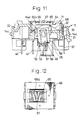
- FIGS. 1 to 4 there is shown a handle operating switch 10 according to the present invention, in which a switch body 12 operated to be switched on and off by a push handle 11 is included.
- This switch body 12 is formed in a module type, that is a number of the switch bodies 12 are provided to be in the same dimensions, and the switch 10 is provided to be capable of accommodating, as required, a plurality of the switch bodies 12 such as three, for example, as shown in the drawings, in the instance of which a mounting of the switch body 12 to a mounting frame 13 is realized by engaging two pairs of engaging projections 14, 14a and 14b, 14c formed at upper position of both longitudinal end faces of the body 12 (only a pair on one end side are shown in FIG.
- an engaging recess 21 is provided in top side face at one of the longitudinal ends of the switch body 12 while on the other end side top face an engaging pivot part 22 is provided, and a piano handle 23 is mounted onto the switch body 12 by engaging projections 24 of the handle 23 into the recess 21 and a privoting projection 25 of the handle 23 in the engaging pivot part 22 of the body 12.
- any further resetting motion than required of the piano handle 23 can be restrained by means of hook-shaped tip ends of the engaging projections 24 of the piano handle 23, the tip ends engaging a locking edge of the engaging recess 22, so that the piano handle 23 can be reset always to the same non-actuated position.
- the switch body 12 comprises a hollow housing 26 formed by a synthetic resin and consisting of top and base housing parts 27 and 28, which are assembled together by means of engaging strips 29, 29a, 29b and 29c extended from the top housing part 27 and respectively having each of engaging slots 30, 30a, 30b and 30c (only three of them are shown in FIG. 2), the strips 29-29c being engaged to engaging projections 31, 31a, 31b and 31c projected on both side walls of the base housing part 28 (only two of these projections are seen in FIG. 2).
- the foregoing engaging projections 14-14c of the switch body 12 are provided to the top housing part 27 for the mounting of the body 12 to the mounting frame 13, and the foregoing engaging recess 21 is also provided in the top housing part 27 at the one end part having the engaging projections 14 and 14a so that the recess 21 existing as a vacancy will provide to the end part a resiliency effective to render the mounting engagement of the projections 14 and 14a into the slots of the mounting frame 13 smoothly realizable.
- top housing part 27 is provided with a top-open chamber 34 for receiving therein the push handle 11 to be movable vertically, i.e., toward and away from bottom wall of the chamber 34, which chamber having in opposing side walls engaging recesses 33 for receiving engaging projections 32 made at longitudinal ends of the push handle 11 and, in the bottom wall, bearing grooves 35 for receiving a later described turning handle.
- the base housing part 28 is formed to have at both longitudinal ends connecting terminal receiving sections 35 and 36, received in one section 35 of which are common terminal plate 37, locking springs 38 and 38a and releasing button 39, while in the other section 36 of which a first connecting terminal assembly of a terminal plate 40 and locking spring 41 as well as a second connecting terminal assembly of a terminal plate 42 and locking spring 43 are disposed together with a release button 44 acting commonly to the first and second connecting terminal assemblies.
- a central receiving section 45 Between the both connecting terminal receiving sections 35 and 36, further, there is defined a central receiving section 45.
- the terminal plate 40 of the first connecting terminal assembly disposed in the other receiving section 36 is extended at an end along an inner side wall of the central receiving section 45 and is then bent toward the center of the section 36 so that this extended end will lie along a support stud 48 on the one end side of the central receiving section 45, and a stationary contact 49 is secured to tip end portion of the extended end of the terminal plate 40.
- further coupling strips 51 are provided for embraceably engaging an end part of a support stud 50 disposed to oppose the foregoing support stud 48 in the central receiving section 45 on one lateral side thereof.
- the terminal plate 42 of the second terminal assembly is formed to ride astride on a further support stud 50a made in the central receiving section 45 on the other lateral side thereof and to have an extended end bent to oppose the extended tip end of the terminal plate 40 having the stationary contact 49, and a further stationary contact 52 is secured to the extended end of the plate 42 to oppose the contact 49.
- the inner frame 47 is formed to include an errected wall having a recess (not shown), in which a movable terminal plate 53 as a switch on-off means is freely engaged specifically at a projection 54 of the plate 53, so that the movable terminal plate 53 will be rockable for an angular range defined by a rock-allowing angle of the recess.
- This movable terminal plate 53 is formed by a conducting material and is brought into contact at a lower end with a conducting bearing plate part 56 made integral with the common terminal plate 37 and disposed between the both support studs 48, 50 and 50a of the central receiving section 45, and a movable contact 57 is secured to upper end part of the movable terminal plate 53 so that, as the movable terminal plate 53 rocks with the lower end made as the fulcrum, the movable contact 57 will achieve the switch on and off operation with each of the stationary contacts 49 and 52 of the terminal plates 40 and 42.
- the switch on-off means comprising the movable terminal plate 53 is interlocked with the turning means which comprises a coil spring 58, turning handle 59 and slide cam means 60 disposed along the inner face of the push handle 11.
- the coil spring 58 is engaged at one end to an upward projection 61 of the movable terminal plate 53 and inserted at the other end into a downward opened axial hole of the turning handle 59 of a cylindrical shape, so as to provide to the movable terminal plate 53 such turning action in response to a rocking motion of the turning handle 59 as will be described later.
- the turning handle 59 per se is disposed to project, through an aperture 62 made in the bottom wall of the chamber 34 of the top housing part 27, into this chamber 34 while engaging a pair of triangular shaft projections 63 formed on opposing both sides of the cylindrical shape freely into the bearing grooves 35 of the top housing part 27.
- a rectangular portion is formed at the top of the turning handle 59, and a pair of engaging projections 64 and 64a are provided to be errected at both longitudinal ends of the rectangular top portion in a direction perpendicular to projecting direction of the shaft projections 63.
- the slide cam means 60 is formed substantially into a frame of rectangular shape, preferably with such thermoplastic resin as polyacetal high in the elasticity, and a pair of camming projections 65 and 65a are provided to both opposing side edges of the rectangular frame shape to be slidingly engageable with the engaging projections 64 and 64a at the top of the turning handle 59. Further, the slide cam means 60 includes a pair of resilient strips 66 and 66a integrally extended inside the frame shape from one side to the other opposing side while transversing the direction in which the camming projections 65 and 65a are provided to oppose and gradually approaching each other at extended ends.
- the push handle 11 is provided in the center of the inner surface with a projection 67 which is held between the resilient strips 66 and 66a so that, upon sliding of the slide cam means 60 in either direction in which the camming projections 65 and 65a are opposing, a resetting force will be provided by the resilient strip 66 or 66a to the means 60 with respect to the projection 67.
- a resetting spring 68 is disposed between the push handle 11 and the bottom of the chamber 34 of the top housing part 27, and this spring 68 is formed preferably in such that the spring 68 is coupled at a central top portion to the push handle 11 and resiliently engages at both side legs with the bottom of the chamber 34 while the legs are gradually opened in downward direction away from the push handle 11, whereby the push handle 11 and eventually the piano handle 23 are constantly urged upward, away from the switch body 12.
- a depression of the push handle 11 against the resilient force of the resetting spring 68 through the depression of the piano handle 23 on its side having the engaging projections 24 in a position shown in FIGS. 5 and 6 causes the slide cam means 60 also to be pushed down, upon which the camming projection 65a on one side of the slide cam means 60 engages at a part of its inside slope with the engaging projection 64a at one end top portion of the turning handle 59 in a state tilted on one side in such position shown in FIGS. 7 and 8.
- the engaging projection 64a of the turning handle 59 is displaced to have eventually the turning handle 59 rocked so that, when the coil spring 58 moves beyond its dead point, the turning handle 59 will be turned to a position shown in FIGS. 9 and 10, accompanying which the movable terminal plate 53 interlocked with the turning handle 59 through the coil spring 58 is also caused to rockingly turn, so that the movable contact 57 of the movable terminal plate 53 will be separated from the stationary contact 52 with which the movable contact 57 has been in the contact closing state but will be brought into the contact closing state with the other opposing stationary contact 49, and the switching action is thereby carried out.
- the distance between the engaging projections 64 and 64a of the turning handle 59 as well as the distance between the engaging camming projections 65 and 65a are so set that, when the slide cam means 60 slides while engaging at one of the camming projections 65 and 65a with one of the engaging projections 64 and 64a of the turning handle 59, the other of the camming projections 65 and 65a is positioned on inner side of the other of the engaging projections 64 and 64a, so as to smoothly and reliably execute the switch on and off operation, whereby the engaging projections 64 and 64a of the turning handle 59 are displaced in counterclockwise direction as shown in FIGS.
- the single switch body 12 of the modular type is mounted to the center of the mounting frame 13 adapted to concurrent mounting of three of the module type switch bodies, and also the single piano handle 23 of a relatively large size is employed for the switch on and off operation, but the dimension of the mounting frame 13, number of the switch body to be mounted and number or size of the piano handle are selectable as required.
- the mounting frame 13A is provided for concurrent mounting of the two module type switch bodies 12A and 12A1, while the piano handle may be divided into two handles 23A and 23A1 in correspondence with the number of the switch bodies 12A and 12A1.
- FIGS. 17 and 18 it is also possible, as shown in FIGS. 17 and 18, to concurrently mount three of the module type switch bodies 12B, 12B1 12B2 to the same mounting frame 13B, together with three-divided piano handles 23B, 23B1 and 23B2 corresponding to the three switch bodies.
- the switch has been referred to as comprising only the switch body 12, mounting frame 13 to which the switch body 12 is mounted, and the piano handle 23 mounted to the switch body
- the mounting frame 13 generally formed by a metal is deemed not acceptable in the appearance
- the dimension and arrangement of the switch body 12, mounting frame 13 and piano handle 23 may be modified as shown in FIG. 21, in which event two relatively smaller piano handles 23D and 23D1 are jointly mounted to a square shaped mounting frame, together with a relatively larger rectangular piano handle 23D2 disposed on a side of the handles 23D and 23D1 in a direction perpendicular to a direction in which the two handles 23D and 23D1 are arranged, and an ornamental plate 70D is fitted over the frame to surround the handles.
- the handle operating switch is provided with a function of indicating the operating state of the switch.
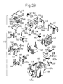
- FIGS. 22 and 23 there is shown another embodiment of the present invention, in which the top housing part 127 is provided with an indicator 200 adjacent the chamber 134.
- the indicator 200 generally comprises an indicator compartment 201 and a printed circuit board 202 on which such indicator circuit as shown in FIG. 24 is mounted.
- FIG. 22 In FIG. 22
- FIG. 24 there is shown an internal circuit of one of the switch bodies forming a three-way switch with two of the switch bodies, in which a luminous diode 204 with which a counter-electromotive-force preventing diode 203 is connected in parallel is inserted on secondary side of a current transformer 146 connected between the common terminal plate 137 and the conducting support plate 156, and an ON indication of load of the switch body 112 is thereby carried out.
- a neon tube 207 to which resistors 205 and 206 are connected is inserted between the terminal plates 140 and 142 to which the stationary contacts are secured, so that an OFF indication of the load connected to the switch body 112 can be carried out by this neon tube 207.
- connection of the circuit board 202 to the terminal plates 140 and 142 may be realized by means of resilient contactors 208 and 208a connected at one end to the printed circuit board 202 and resiliently contacted at the other end with the terminal plates 208 and 208a.
- the indicator compartment 201 is opened on top side to form an aperture 209, the luminous diode 204 and neon tube 207 are disposed inside the aperture 209, and preferably a light permeating cover 210 is fitted to the aperture 209, so that the operating state of the handle operating switch will be readily visible constantly through the cover 210.
- the foregoing arrangement will function as a firefly-glimmer-like pilot lamp lighting in the dark when the lighting equipment is turned off. In the embodiment of FIGS.
- the base housing part 128 is expanded at the bottom of the central receiving section 145 for receiving therein a current transformer 146, and an inner frame 147 is disposed at a position above the current transformer 146 and corresponding to the position of the bottom plate of the base housing part 28 in the foregoing embodiment.
- This inner frame 147 is provided with the support studs 148 and 150 for seating therealong the terminal plates 140 and 142, and with a lateral stud having in a side face a V-shaped recess 155 for freely rockably engaging therein a projection 154 of the movable terminal plate 153.
- the conducting bearing plate part 156 is formed as divided from the common terminal plate 137 but as connected thereto, for rockably bearing thereon the movable terminal plate 153.
- other constituent parts are the same as those in the embodiment of FIGS. 1-4 and are denoted by the same reference numerals as those used in FIGS. 1-4 but as added by 100.
- the size of the mounting frame, number of the switch body to be mounted to the frame and size and number of the piano handle as well as the use of the ornamental plate having the aperture for disposing therein the piano handle or handles may be properly selected as required.
- the arrangement may take an aspect of disposing three of the piano handles 123C, 123C1 and 123C2 within the aperture 169 of the ornamental plate 170, in the same manner as in the aspect of FIGS.
- the arrangement may be in an aspect of the two relatively smaller piano handles 123D and 123D1 arranged in two stages and the one relatively larger piano handle 123D2 arranged on a lateral side of the above two while all the three handles are disposed in the ornamental plate 170D.
- the respective piano handles 123D, 123D1 and 123D2 are provided with the light permeating portions 221B, 221B1 and 221B2 at positions corresponding to the light permeating covers of the indicators in the switch bodies.
Abstract
Description
- This invention relates to handle operating switches and, more particularly, to a switch the switching operation of which is realized by such depressing action as a piano-key touch operation of a handle of the switch.
- The handle operating switches of the kind referred to are installed on housing interior wall or the like for effective utilization in ON and OFF control of lighting fixtures and any other loads.
- The known handle operating switches generally comprise a casing and a switch on-off means provided in the casing, in which switch on-off means a movable contact is provided to a movable contactor mounted rockably with its lower portion made as a fulcrum for switching on and off operation with respect to a stationary contact provided to a stationary terminal plate through turning operation of the movable contactor, the switch on-off means is operated through a handle member disposed for seesaw motion, that is, a rocking motion, and the movable contactor is thereby actuated to be turned for switching on and off the stationary and movable contacts. In the handle operating switch of the foregoing arrangement, however, there has been a problem that a designing restriction arises due to an inherent difference in stationary positions after every on or off operation of the handle. That is, the handle is required to be rocked from one position to the other upon every operation of the switch, and an improvement in the operation ability has been demanded.
- In U.S. Patent No. 3,576,962 to Jean-Pierre Edmond Nicolas, on the other hand, there has been disclosed a push contact device in which an operating plate is placed on top side of a base plate, a metal plate is attached to a pushrod connected to the operating plate which a first terminal is connected to an end of the metal plate, a stirrup movable member is carried on the other end of the metal plate, and a movable contact engageable with and disengageable from a second terminal is provided to the movable member, so that the contact on and off operation relying not on the seesaw movement but on a depressing operation of the operating plate may be realized. With this contact on and off arrangement, however, the movable contact is arranged not for alternate on and off operation with respect to opposing stationary contacts and the pushrod is coupled to the center of the operating plate, so that it will be required to depress the entire body of the operating plate so as to render the operation ability to be troublesome.
- A primary object of the present invention is, therefore, to provide a handle operating switch that can realize the on-off operation with a depressing action of a handle having constantly the same stationary position always in the same direction such as the piano-key touching action, can restrain any restriction in the design, and can improve the operation ability.
- According to the present invention, this object can be realized by a handle operating switch comprising a switch body in which a switch on-off means having a movable contact is supported in a housing to be rockable for engagement and disengagement of the movable contact with and from a stationary contact also disposed in the housing, and a turning means is provided for turning operation of the on-off means in response to a depressing action of a push handle to which a resetting spring load is applied, characterized in that a turning handle is coupled through a coil spring to the switch on-off means and provided to be rockable in alignment with rocking direction of the on-off means and is provided at both side parts of an end opposing the push handle with engaging projections, a slide cam means is disposed slidable along an interior surface of the push handle, the slide cam means being provided at both end parts with engaging cam parts which are engageable with the engaging projections of the turning handle approaching the push handle upon depression of the push handle and are slidable in a direction intersecting at right angles a direction of the depression of the push handle upon the engagement of the cam parts, a resilient resetting means formed integral with the slide cam means is provided to be engaged at free end of the resetting means with the push handle to provide thereto a resilient force acting in a direction reverse to the sliding direction of the slide cam means upon the sliding thereof, and a piano handle pivotably engaged on one edge side to the housing is disposed for a depressing action with respect to the push handle upon depression on the other edge side of the piano handle.
- Other objects and advantages of the present invention will be made clear by the description of the invention detailed in the followings with reference to preferred embodiments shown in accompanying drawings.
-
- FIGURE 1 shows in a perspective view a handle operation switch according to the present invention, as disassembled into main components;
- FIG. 1A is a reverse side perspective view of a piano handle of the switch shown in FIG. 1;
- FIG. 2 is a perspective view of a switch body of the switch shown in FIG. 1, as disassembled into constituent parts;
- FIGS. 3 and 4 are explanatory views in cross-sectional views for the operation of the piano handle in the switch of FIG. 1;
- FIGS. 5, 7, 9 and 11 are cross-sectional views of a part of the switch body in the switch of FIG. 1 for showing respectively different operating states in the switch body;
- FIGS. 6, 8, 10 and 12 are bottom plan views of the push handle with the slide cam means assembled with the handle for showing respectively different operating states thereof each of which corresponding to each state of FIGS. 5, 7, 9 and 11;
- FIG. 13 is a schematic explanatory view for the relationship of the switch body to the mounting frame and piano handle in the switch shown in FIG. 1;
- FIG. 14 is a schematic plan view of the switch shown in FIGS. 1 and 13;
- FIG. 15 is a schematic explanatory view for the relationship of the switch body to the mounting frame and piano handle in another working aspect of the handle operating switch according to the present invention;
- FIG. 16 is a schematic plan view of the switch shown in FIG. 15;
- FIG. 17 is a schematic explanatory view for the relationship of the switch body to the mounting frame and piano handle in a further working aspect of the switch according to the present invention;
- FIG. 18 is a schematic plan view of the switch shown in FIG. 17;
- FIG. 19 is a more detailed plan view of the switch shown in FIG. 17;
- FIG. 20 is a side view of the switch shown in FIG. 17 or 19 with the switch bodies omitted;
- FIG. 21 is a detailed plan view in still another working aspect of the handle operating switch according to the present invention;
- FIG. 22 shows in a cross-sectional view the handle operating switch in another embodiment of the present invention;
- FIG. 23 shows in a perspective view as disassembled the switch shown in FIG. 22;
- FIG. 24 is a diagram showing an indicator circuit employed in the switch shown in FIG. 22;
- FIG. 25 is a detailed plan view in another working aspect of the handle operating switch in the embodiment of FIG. 22;
- FIG. 26 is a side view of the switch shown in FIG. 25 with the switch bodies omitted; and
- FIG. 27 is a detailed plan view in still another working aspect of the handle operating switch according to the present invention.
- While the present invention shall now be detailed with reference to the embodiments shown in the accompanying drawings, it should be appreciated that the intention is not to limit the invention only to these embodiments but rather to include all modifications, alterations and equivalent arrangements possible within the scope of appended claims.
- Referring to FIGS. 1 to 4, there is shown a handle operating switch 10 according to the present invention, in which a
switch body 12 operated to be switched on and off by apush handle 11 is included. Thisswitch body 12 is formed in a module type, that is a number of theswitch bodies 12 are provided to be in the same dimensions, and the switch 10 is provided to be capable of accommodating, as required, a plurality of theswitch bodies 12 such as three, for example, as shown in the drawings, in the instance of which a mounting of theswitch body 12 to amounting frame 13 is realized by engaging two pairs ofengaging projections holes mounting frame 13. When, for example, only oneswitch body 12 is to be mounted to themounting frame 13, the engaging projections 14-14c of theswitch body 12 are to be engaged in central pairs of theengaging slots mounting frame 13. - In top side face at one of the longitudinal ends of the
switch body 12, anengaging recess 21 is provided while on the other end side top face anengaging pivot part 22 is provided, and apiano handle 23 is mounted onto theswitch body 12 byengaging projections 24 of thehandle 23 into therecess 21 and aprivoting projection 25 of thehandle 23 in theengaging pivot part 22 of thebody 12. When, in this case, one side having theprojections 24 of thepiano handle 23 is depressed to be rotated with the other side having thepivoting projection 25 of thehandle 23 made as a fulcrum and with theprojections 24 caused to slide in therecess 21, thepush handle 11 of theswitch body 12 is depressed by thepiano handle 23 through its optimumly designed inner surface, and a switching operation with respect to theswitch body 12 is carried out. While a resetting force against the depression of thepiano handle 23 is provided simultaneously upon resetting action of thepush handle 11, on the other hand, any further resetting motion than required of thepiano handle 23 can be restrained by means of hook-shaped tip ends of theengaging projections 24 of thepiano handle 23, the tip ends engaging a locking edge of theengaging recess 22, so that thepiano handle 23 can be reset always to the same non-actuated position. - The
switch body 12 comprises ahollow housing 26 formed by a synthetic resin and consisting of top andbase housing parts engaging strips top housing part 27 and respectively having each ofengaging slots projections switch body 12 are provided to thetop housing part 27 for the mounting of thebody 12 to themounting frame 13, and the foregoingengaging recess 21 is also provided in thetop housing part 27 at the one end part having theengaging projections projections mounting frame 13 smoothly realizable. Further, thetop housing part 27 is provided with a top-open chamber 34 for receiving therein thepush handle 11 to be movable vertically, i.e., toward and away from bottom wall of thechamber 34, which chamber having in opposing sidewalls engaging recesses 33 for receivingengaging projections 32 made at longitudinal ends of thepush handle 11 and, in the bottom wall, bearinggrooves 35 for receiving a later described turning handle. - The
base housing part 28 is formed to have at both longitudinal ends connectingterminal receiving sections section 35 of which arecommon terminal plate 37, lockingsprings button 39, while in theother section 36 of which a first connecting terminal assembly of aterminal plate 40 and lockingspring 41 as well as a second connecting terminal assembly of aterminal plate 42 and lockingspring 43 are disposed together with a release button 44 acting commonly to the first and second connecting terminal assemblies. Between the both connectingterminal receiving sections central receiving section 45. - In the present instance, the
terminal plate 40 of the first connecting terminal assembly disposed in theother receiving section 36 is extended at an end along an inner side wall of thecentral receiving section 45 and is then bent toward the center of thesection 36 so that this extended end will lie along asupport stud 48 on the one end side of thecentral receiving section 45, and astationary contact 49 is secured to tip end portion of the extended end of theterminal plate 40. At base part of theterminal plate 40,further coupling strips 51 are provided for embraceably engaging an end part of asupport stud 50 disposed to oppose theforegoing support stud 48 in thecentral receiving section 45 on one lateral side thereof. Theterminal plate 42 of the second terminal assembly is formed to ride astride on afurther support stud 50a made in thecentral receiving section 45 on the other lateral side thereof and to have an extended end bent to oppose the extended tip end of theterminal plate 40 having thestationary contact 49, and a furtherstationary contact 52 is secured to the extended end of theplate 42 to oppose thecontact 49. - Further, the inner frame 47 is formed to include an errected wall having a recess (not shown), in which a movable
terminal plate 53 as a switch on-off means is freely engaged specifically at aprojection 54 of theplate 53, so that themovable terminal plate 53 will be rockable for an angular range defined by a rock-allowing angle of the recess. Thismovable terminal plate 53 is formed by a conducting material and is brought into contact at a lower end with a conductingbearing plate part 56 made integral with thecommon terminal plate 37 and disposed between the bothsupport studs central receiving section 45, and amovable contact 57 is secured to upper end part of themovable terminal plate 53 so that, as themovable terminal plate 53 rocks with the lower end made as the fulcrum, themovable contact 57 will achieve the switch on and off operation with each of thestationary contacts terminal plates - The switch on-off means comprising the
movable terminal plate 53 is interlocked with the turning means which comprises acoil spring 58, turninghandle 59 and slide cam means 60 disposed along the inner face of thepush handle 11. In this case, thecoil spring 58 is engaged at one end to anupward projection 61 of the movableterminal plate 53 and inserted at the other end into a downward opened axial hole of theturning handle 59 of a cylindrical shape, so as to provide to themovable terminal plate 53 such turning action in response to a rocking motion of theturning handle 59 as will be described later. Theturning handle 59 per se is disposed to project, through anaperture 62 made in the bottom wall of thechamber 34 of thetop housing part 27, into thischamber 34 while engaging a pair oftriangular shaft projections 63 formed on opposing both sides of the cylindrical shape freely into thebearing grooves 35 of thetop housing part 27. A rectangular portion is formed at the top of theturning handle 59, and a pair ofengaging projections shaft projections 63. - The slide cam means 60 is formed substantially into a frame of rectangular shape, preferably with such thermoplastic resin as polyacetal high in the elasticity, and a pair of
camming projections engaging projections turning handle 59. Further, the slide cam means 60 includes a pair ofresilient strips camming projections push handle 11 is provided in the center of the inner surface with aprojection 67 which is held between theresilient strips camming projections resilient strip means 60 with respect to theprojection 67. Further, a resettingspring 68 is disposed between thepush handle 11 and the bottom of thechamber 34 of thetop housing part 27, and thisspring 68 is formed preferably in such that thespring 68 is coupled at a central top portion to thepush handle 11 and resiliently engages at both side legs with the bottom of thechamber 34 while the legs are gradually opened in downward direction away from thepush handle 11, whereby thepush handle 11 and eventually thepiano handle 23 are constantly urged upward, away from theswitch body 12. - Referring next to the operation of the handle operating switch according to the present invention, a depression of the
push handle 11 against the resilient force of the resettingspring 68 through the depression of thepiano handle 23 on its side having theengaging projections 24 in a position shown in FIGS. 5 and 6 causes the slide cam means 60 also to be pushed down, upon which thecamming projection 65a on one side of the slide cam means 60 engages at a part of its inside slope with theengaging projection 64a at one end top portion of theturning handle 59 in a state tilted on one side in such position shown in FIGS. 7 and 8. As thepush handle 11 is further depressed in response to the depression of thepiano handle 23, theengaging projection 64a of theturning handle 59 is displaced to have eventually theturning handle 59 rocked so that, when thecoil spring 58 moves beyond its dead point, theturning handle 59 will be turned to a position shown in FIGS. 9 and 10, accompanying which themovable terminal plate 53 interlocked with theturning handle 59 through thecoil spring 58 is also caused to rockingly turn, so that themovable contact 57 of themovable terminal plate 53 will be separated from thestationary contact 52 with which themovable contact 57 has been in the contact closing state but will be brought into the contact closing state with the other opposingstationary contact 49, and the switching action is thereby carried out. - In the foregoing structure, the distance between the
engaging projections turning handle 59 as well as the distance between theengaging camming projections camming projections engaging projections turning handle 59, the other of thecamming projections engaging projections engaging projections turning handle 59 are displaced in counterclockwise direction as shown in FIGS. 5, 7 and 9 following the rocking motion of theturning handle 59 due to the depression of thepush handle 11, and thecamming projections engaging projections resilient strip projections handle 59 beyond its level position, the slide cam means 60 still slides in the leftward direction so as not to hinder the turning handle 59 from rockingly turning. Since the slide cam means 60 is provided to involve no frictional resistance upon the sliding, further, the turninghandle 59 and slide cam means 60 are assured to achieve their mutual operation in smooth manner. - When the depressing force o the piano handle 23 is released after the foregoing turning operation, the push handle 11 and piano handle 23 are reset to the original position by means of the resilient force of the resetting
spring 68 as shown in FIGS. 11 and 12, and the slide cam means 60 is also caused to slide to be reset to the original position by the resilient force of theresilient strips - When the piano handle 23 is depressed again on the side of the engaging
projections 24, the above described operation is carried out in reverse manner, so that themovable terminal plate 53 is rocked to carry out the contact switching operation, and themovable contact 57 is separated from thestationary contact 49 and brought into contact closing state with the otherstationary contact 52. - In the foregoing embodiment, the description has been made to that, as schematically shown in FIGS. 13 and 14, the
single switch body 12 of the modular type is mounted to the center of the mountingframe 13 adapted to concurrent mounting of three of the module type switch bodies, and also thesingle piano handle 23 of a relatively large size is employed for the switch on and off operation, but the dimension of the mountingframe 13, number of the switch body to be mounted and number or size of the piano handle are selectable as required. As shown in FIGS. 15 and 16, for example, the mountingframe 13A is provided for concurrent mounting of the two moduletype switch bodies 12A and 12A1, while the piano handle may be divided into twohandles 23A and 23A1 in correspondence with the number of theswitch bodies 12A and 12A1. Further, it is also possible, as shown in FIGS. 17 and 18, to concurrently mount three of the moduletype switch bodies 12B, 12B1 12B2 to thesame mounting frame 13B, together with three-divided piano handles 23B, 23B1 and 23B2 corresponding to the three switch bodies. - While in the foregoing embodiment, on the other hand, the switch has been referred to as comprising only the
switch body 12, mountingframe 13 to which theswitch body 12 is mounted, and the piano handle 23 mounted to the switch body, it will be preferable, so long as the mountingframe 13 generally formed by a metal is deemed not acceptable in the appearance, to employ additionally such anornamental plate 70 as shown in FIGS. 19 and 20, which is made of a synthetic resin to have anaperture 69 for disposing therein three, for example, of the piano handles 23C, 23C1 and 23C2 and is mounted also to the mountingframe 13 by means of screws or the like so as to cover theframe 13. - The dimension and arrangement of the
switch body 12, mountingframe 13 and piano handle 23 may be modified as shown in FIG. 21, in which event two relatively smaller piano handles 23D and 23D1 are jointly mounted to a square shaped mounting frame, together with a relatively larger rectangular piano handle 23D2 disposed on a side of thehandles 23D and 23D1 in a direction perpendicular to a direction in which the twohandles 23D and 23D1 are arranged, and anornamental plate 70D is fitted over the frame to surround the handles. - According to another feature of the present invention, the handle operating switch is provided with a function of indicating the operating state of the switch. Referring to FIGS. 22 and 23, there is shown another embodiment of the present invention, in which the
top housing part 127 is provided with anindicator 200 adjacent thechamber 134. Theindicator 200 generally comprises anindicator compartment 201 and a printedcircuit board 202 on which such indicator circuit as shown in FIG. 24 is mounted. In FIG. 24, there is shown an internal circuit of one of the switch bodies forming a three-way switch with two of the switch bodies, in which aluminous diode 204 with which a counter-electromotive-force preventing diode 203 is connected in parallel is inserted on secondary side of acurrent transformer 146 connected between thecommon terminal plate 137 and the conductingsupport plate 156, and an ON indication of load of theswitch body 112 is thereby carried out. On the other hand, aneon tube 207 to whichresistors terminal plates switch body 112 can be carried out by thisneon tube 207. In the present instance, the connection of thecircuit board 202 to theterminal plates resilient contactors circuit board 202 and resiliently contacted at the other end with theterminal plates - The
indicator compartment 201 is opened on top side to form anaperture 209, theluminous diode 204 andneon tube 207 are disposed inside theaperture 209, and preferably alight permeating cover 210 is fitted to theaperture 209, so that the operating state of the handle operating switch will be readily visible constantly through thecover 210. It should be appreciated that, in the event where the load connected to the switch is a lighting equipment, the foregoing arrangement will function as a firefly-glimmer-like pilot lamp lighting in the dark when the lighting equipment is turned off. In the embodiment of FIGS. 22 and 23, further, thebase housing part 128 is expanded at the bottom of thecentral receiving section 145 for receiving therein acurrent transformer 146, and aninner frame 147 is disposed at a position above thecurrent transformer 146 and corresponding to the position of the bottom plate of thebase housing part 28 in the foregoing embodiment. Thisinner frame 147 is provided with thesupport studs terminal plates recess 155 for freely rockably engaging therein aprojection 154 of the movableterminal plate 153. The conductingbearing plate part 156 is formed as divided from thecommon terminal plate 137 but as connected thereto, for rockably bearing thereon the movableterminal plate 153. In the arrangement of FIGS. 22 and 23, other constituent parts are the same as those in the embodiment of FIGS. 1-4 and are denoted by the same reference numerals as those used in FIGS. 1-4 but as added by 100. - In the handle operating switch having the indicating function as shown in FIGS. 22 and 23, too, the size of the mounting frame, number of the switch body to be mounted to the frame and size and number of the piano handle as well as the use of the ornamental plate having the aperture for disposing therein the piano handle or handles may be properly selected as required. As shown in FIGS. 25 and 26, for example, the arrangement may take an aspect of disposing three of the piano handles 123C, 123C1 and 123C2 within the aperture 169 of the
ornamental plate 170, in the same manner as in the aspect of FIGS. 19 and 20, except for an additional provision of thelight permeating portions 221A, 221A1 and 221A2 corresponding in the position to the light permeating covers of the indicators of the respective switch bodies on the side of the pivoting side of the respective piano handles 123C, 123C1 and 123C2. Alternatively, as shown in FIG. 27, the arrangement may be in an aspect of the two relatively smaller piano handles 123D and 123D1 arranged in two stages and the one relatively larger piano handle 123D2 arranged on a lateral side of the above two while all the three handles are disposed in theornamental plate 170D. Also in this aspect, the respective piano handles 123D, 123D1 and 123D2 are provided with thelight permeating portions 221B, 221B1 and 221B2 at positions corresponding to the light permeating covers of the indicators in the switch bodies.
Claims (10)
- A handle operating switch comprising a switch body in which a switch on-off means having a movable contact is supported in a housing to be rockable for engagement and disengagement of said movable contact with and from a stationary contact also disposed in said housing, and a turning means is provided for turning operation of said switch on-off means in response to a depressing action of a push handle to which a resetting spring load is applied, characterized in that a turning handle is coupled through a coil spring to the switch on-off means and provided to be rockable in alignment with rocking direction of the on-off means and is provided at both side parts of an end opposing the push handle with engaging projections, a slide cam means is disposed slidable along an interior surface of the push handle, said slide cam means being provided at both end parts with engaging cam parts which are engageable with the engaging projections of the turning handle approaching the push handle upon depression of the push handle and are slidable in a direction intersecting at right angles a direction of the depression of the push handle upon the engagement of the engaging cam parts, a resilient resetting means formed integral with the slide cam means is provided to be engaged at free end of the resetting means with the push handle to provide thereto a resilient force acting in a direction reverse to the sliding direction of the slide cam means upon the sliding thereof, and a piano handle pivotably engaged on one edge side to the housing is disposed for a depressing action with respect to the push handle upon depression on the other edge side of the piano handle.
- The switch according to claim 1 wherein said housing is provided on one end side of top surface with an engaging recess and on the other end side with an engaging pivot part, and said piano handle is provided on one side edge with an engaging projection to be engaged in said engaging recess of said housing and on the other side edge with a pivoting projection to be engaged with said engaging pivot part of the housing.
- The switch according to claim 1 wherein said switch body is formed in a module type mountable concurrently in a plurality to a single mounting frame, and said piano handle is divided into a number corresponding to said plurality of said switch body.
- The switch according to claim 1 wherein said switch on-off means comprises a pair of terminal plates disposed to oppose each other in said housing of said switch body and a movable terminal plate, said stationary contact is provided in a pair each of which is secured to each of said stationary terminal plates, and said movable contact is secured to said movable terminal plate for alternately engaging with and disengaging from said stationary contacts on said opposing terminal plates.
- The switch according to claim 1 wherein said engaging projections of said turning handle are provided as erected on the top of the turning handle, said slide cam means is formed substantially in a rectangular outline, and said engaging cam parts are provided to lower face of both opposing end sides of said slide cam means.
- The switch according to claim 5 wherein said resilient resetting means comprises a pair of resilient strips extended from one side edge toward an opposing side edge to gradually approach each other at extended ends.
- The switch according to claim 1 wherein said engaging projections of said turning handle and said engaging cam parts of said slide cam means are provided to have a distance between the projections and between the cam parts so set that, when the slide cam means slides with one of the engaging cam parts engaged with one of the engaging projections of the turning handle, the other engaging cam part can be positioned inside the other engaging projection, before the rocking turning handle reaches a level position.
- The switch according to claim 1 wherein said switch body further comprises a luminous means for indicating the operating state in a manner visible from the exterior, said indicating means is provided in said housing to be closer to said pivoting side edge of said piano handle, and said piano handle is provided with a light permeating part at a position on one side edge and corresponding to that of said indicating means.
- The switch according to claim 8 wherein said switch body is formed in a module type mountable concurrently in a plurality to a single mounting frame, and said piano handle is divided into a number corresponding to said plurality of said switch bodies.
- The switch according to claim 9 wherein said luminous indicating means is provided to more than one of said plurality of said switch bodies, and said light permeating part is provided to more than one of said divided piano handles corresponding to the switch bodies.
Applications Claiming Priority (4)
| Application Number | Priority Date | Filing Date | Title |
|---|---|---|---|
| JP116066/90 | 1990-05-02 | ||
| JP2116066A JP3033905B2 (en) | 1990-05-02 | 1990-05-02 | Piano handle switch device |
| JP11606390A JP3020252B2 (en) | 1990-05-02 | 1990-05-02 | Piano handle switch |
| JP116063/90 | 1990-05-02 |
Publications (3)
| Publication Number | Publication Date |
|---|---|
| EP0454908A2 true EP0454908A2 (en) | 1991-11-06 |
| EP0454908A3 EP0454908A3 (en) | 1992-05-20 |
| EP0454908B1 EP0454908B1 (en) | 1995-10-18 |
Family
ID=26454445
Family Applications (1)
| Application Number | Title | Priority Date | Filing Date |
|---|---|---|---|
| EP90203419A Expired - Lifetime EP0454908B1 (en) | 1990-05-02 | 1990-12-18 | Handle operating switch |
Country Status (4)
| Country | Link |
|---|---|
| US (1) | US5107084A (en) |
| EP (1) | EP0454908B1 (en) |
| KR (1) | KR930010965B1 (en) |
| DE (1) | DE69023122T2 (en) |
Cited By (6)
| Publication number | Priority date | Publication date | Assignee | Title |
|---|---|---|---|---|
| FR2786312A1 (en) * | 1998-11-25 | 2000-05-26 | Valeo Electronique | KEY CONTROL DEVICE, PARTICULARLY FOR MOTOR VEHICLE EQUIPMENT |
| EP1261001A2 (en) * | 2001-05-23 | 2002-11-27 | Domustech S.P.A. | Slim pushbutton unit |
| FR2938371A1 (en) * | 2008-11-13 | 2010-05-14 | Legrand France | ELECTRICAL SWITCH TYPE "PUSH-PUSH" OR "PUSH-DOWN" WITH WAYS OF DRIVING NUTS |
| FR2996952A1 (en) * | 2012-10-12 | 2014-04-18 | Legrand France | Electric switch i.e. push-push type electric switch, for use in room, has drive unit comprising spring wire whose deformable bending part is supported on nut to swing brush when actuating key is moved from rest position to inserted position |
| EP2903012A4 (en) * | 2012-09-28 | 2015-09-16 | Panasonic Ip Man Co Ltd | Switch |
| WO2017136657A1 (en) * | 2016-02-05 | 2017-08-10 | Crown Equiment Corporation | Control elements for materials handling vehicles |
Families Citing this family (10)
| Publication number | Priority date | Publication date | Assignee | Title |
|---|---|---|---|---|
| DE4447527C2 (en) * | 1993-09-09 | 1998-01-29 | Eaton Controls Gmbh | Reading light for the interior of a motor vehicle |
| DE4425154C1 (en) * | 1994-07-16 | 1995-10-19 | Valeo Borg Instr Verw Gmbh | Push-button actuated switch with elongated pushbutton and transmission lever |
| TW375749B (en) * | 1997-05-27 | 1999-12-01 | Matsushita Electric Works Ltd | Push-button switch assembly |
| JPH1186682A (en) * | 1997-09-12 | 1999-03-30 | Matsushita Electric Works Ltd | Switch and switch apparatus using the switch |
| JPH1116448A (en) * | 1997-06-25 | 1999-01-22 | Matsushita Electric Works Ltd | Push-button switch and switch device using thereof |
| DE20004953U1 (en) | 2000-03-10 | 2000-08-10 | Petri Ag | Steering wheel for motor vehicles with a switching device for actuating an electrical functional group of a motor vehicle |
| JP4281703B2 (en) * | 2005-04-18 | 2009-06-17 | パナソニック電工株式会社 | Handle and switch including the same |
| CN103501931B (en) | 2011-03-23 | 2016-08-10 | Sms物流系统有限责任公司 | Device for thick strip sampling |
| CN206584853U (en) * | 2016-12-30 | 2017-10-24 | 施耐德电气(澳大利亚)有限公司 | Transmission device, button switch and socket for button switch |
| CN206421980U (en) * | 2016-12-30 | 2017-08-18 | 施耐德电气(澳大利亚)有限公司 | Transmission device, button switch and socket for button switch |
Citations (4)
| Publication number | Priority date | Publication date | Assignee | Title |
|---|---|---|---|---|
| GB1390759A (en) * | 1972-08-16 | 1975-04-16 | Marrero P F | Electric switch |
| DE2402613A1 (en) * | 1974-01-21 | 1975-07-24 | Vedder Gmbh Geb | Rocker switch with two-position rocker arm - has rocker arm mounted on cover frame against spring force affording depression |
| DE3046831A1 (en) * | 1980-12-12 | 1982-07-08 | SWF-Spezialfabrik für Autozubehör Gustav Rau GmbH, 7120 Bietigheim-Bissingen | Push-button switch with linear actuator - has stop members corresponding with those on changeover rocker for holding actuator in hold-down position |
| EP0101958A2 (en) * | 1982-07-30 | 1984-03-07 | Omron Tateisi Electronics Co. | Push button switch |
Family Cites Families (3)
| Publication number | Priority date | Publication date | Assignee | Title |
|---|---|---|---|---|
| US3495058A (en) * | 1968-02-12 | 1970-02-10 | Michael Theodor Davy | Plunger actuated alternate make and break switch mechanism with snap acting compression spring |
| DE3205389C2 (en) * | 1982-02-16 | 1984-07-19 | Robert Seuffer GmbH & Co, 7260 Calw | Key switch |
| US4754106A (en) * | 1987-03-23 | 1988-06-28 | Symbolic Displays, Inc. | Double cammed push-button switch and methodology for operation of the same |
-
1990
- 1990-12-18 DE DE69023122T patent/DE69023122T2/en not_active Expired - Fee Related
- 1990-12-18 EP EP90203419A patent/EP0454908B1/en not_active Expired - Lifetime
- 1990-12-20 US US07/631,143 patent/US5107084A/en not_active Expired - Fee Related
- 1990-12-24 KR KR1019900021662A patent/KR930010965B1/en not_active IP Right Cessation
Patent Citations (4)
| Publication number | Priority date | Publication date | Assignee | Title |
|---|---|---|---|---|
| GB1390759A (en) * | 1972-08-16 | 1975-04-16 | Marrero P F | Electric switch |
| DE2402613A1 (en) * | 1974-01-21 | 1975-07-24 | Vedder Gmbh Geb | Rocker switch with two-position rocker arm - has rocker arm mounted on cover frame against spring force affording depression |
| DE3046831A1 (en) * | 1980-12-12 | 1982-07-08 | SWF-Spezialfabrik für Autozubehör Gustav Rau GmbH, 7120 Bietigheim-Bissingen | Push-button switch with linear actuator - has stop members corresponding with those on changeover rocker for holding actuator in hold-down position |
| EP0101958A2 (en) * | 1982-07-30 | 1984-03-07 | Omron Tateisi Electronics Co. | Push button switch |
Cited By (12)
| Publication number | Priority date | Publication date | Assignee | Title |
|---|---|---|---|---|
| FR2786312A1 (en) * | 1998-11-25 | 2000-05-26 | Valeo Electronique | KEY CONTROL DEVICE, PARTICULARLY FOR MOTOR VEHICLE EQUIPMENT |
| EP1005056A1 (en) * | 1998-11-25 | 2000-05-31 | Valeo Electronique | Key switch, especially for automotive vehicle equipment |
| EP1261001A2 (en) * | 2001-05-23 | 2002-11-27 | Domustech S.P.A. | Slim pushbutton unit |
| EP1261001A3 (en) * | 2001-05-23 | 2005-02-09 | ABB Sace S.p.A. | Slim pushbutton unit |
| FR2938371A1 (en) * | 2008-11-13 | 2010-05-14 | Legrand France | ELECTRICAL SWITCH TYPE "PUSH-PUSH" OR "PUSH-DOWN" WITH WAYS OF DRIVING NUTS |
| EP2187414A1 (en) * | 2008-11-13 | 2010-05-19 | Legrand France | Electrical "push-push" or "push-down" switch with a drive mechanism for the box |
| CN101901699B (en) * | 2008-11-13 | 2013-09-25 | 勒格朗法国公司 | Electrical 'push-push' or 'push-down' changeover switch |
| EP2903012A4 (en) * | 2012-09-28 | 2015-09-16 | Panasonic Ip Man Co Ltd | Switch |
| FR2996952A1 (en) * | 2012-10-12 | 2014-04-18 | Legrand France | Electric switch i.e. push-push type electric switch, for use in room, has drive unit comprising spring wire whose deformable bending part is supported on nut to swing brush when actuating key is moved from rest position to inserted position |
| WO2017136657A1 (en) * | 2016-02-05 | 2017-08-10 | Crown Equiment Corporation | Control elements for materials handling vehicles |
| KR20180108681A (en) * | 2016-02-05 | 2018-10-04 | 크라운 이큅먼트 코포레이션 | Control elements for material handling vehicles |
| US11661325B2 (en) | 2016-02-05 | 2023-05-30 | Crown Equipment Corporation | Control elements for materials handling vehicles |
Also Published As
| Publication number | Publication date |
|---|---|
| DE69023122D1 (en) | 1995-11-23 |
| DE69023122T2 (en) | 1996-06-20 |
| KR930010965B1 (en) | 1993-11-18 |
| EP0454908A3 (en) | 1992-05-20 |
| KR910020770A (en) | 1991-12-20 |
| EP0454908B1 (en) | 1995-10-18 |
| US5107084A (en) | 1992-04-21 |
Similar Documents
| Publication | Publication Date | Title |
|---|---|---|
| EP0454908B1 (en) | Handle operating switch | |
| USRE30435E (en) | Keyboard switch arrangement and key switch useable therein | |
| JP2605124B2 (en) | switch | |
| US3403236A (en) | Electrical switch having a one-piece actuator and spring arm structure | |
| US5213204A (en) | Rocker switch | |
| US4689455A (en) | Snap fitted push-button switch actuator assembly | |
| US5626223A (en) | Cam-assisted switch | |
| US3519775A (en) | Rocker switch centered by circular loop spring members coiled in compression | |
| US3789173A (en) | Alternate action switch convertible to momentary by putting latch on different pivot | |
| US6906269B2 (en) | Multi-directional slide switch | |
| TW200305899A (en) | Push button switch | |
| US3242298A (en) | Mounting means for operator of electric switch | |
| US4694130A (en) | Illuminated pushbutton switch with unitary spring and contact | |
| US4394555A (en) | Switch assembly with pivoted actuator | |
| US5566819A (en) | Push button switch with over center bridge | |
| US6515242B2 (en) | Switch device | |
| US4332990A (en) | Miniature illuminated push button switch and indicator light | |
| AU2018204641A1 (en) | Push-button switch | |
| US4640998A (en) | Push button switch with compound contact lever action | |
| EP1202309B1 (en) | Interlocking type multi-push-switch device | |
| JP2554719Y2 (en) | Switch unit | |
| AU2018204743B2 (en) | Push button switch | |
| US3402620A (en) | Pushbutton electric switch operator with maintaining mechanism | |
| US4447687A (en) | Pushbutton switch | |
| US3280277A (en) | Quick acting switch |
Legal Events
| Date | Code | Title | Description |
|---|---|---|---|
| PUAI | Public reference made under article 153(3) epc to a published international application that has entered the european phase |
Free format text: ORIGINAL CODE: 0009012 |
|
| AK | Designated contracting states |
Kind code of ref document: A2 Designated state(s): DE FR GB IT |
|
| 17P | Request for examination filed |
Effective date: 19920130 |
|
| PUAL | Search report despatched |
Free format text: ORIGINAL CODE: 0009013 |
|
| AK | Designated contracting states |
Kind code of ref document: A3 Designated state(s): DE FR GB IT |
|
| 17Q | First examination report despatched |
Effective date: 19940628 |
|
| GRAA | (expected) grant |
Free format text: ORIGINAL CODE: 0009210 |
|
| AK | Designated contracting states |
Kind code of ref document: B1 Designated state(s): DE FR GB IT |
|
| REF | Corresponds to: |
Ref document number: 69023122 Country of ref document: DE Date of ref document: 19951123 |
|
| ITF | It: translation for a ep patent filed |
Owner name: BUGNION S.P.A. |
|
| ET | Fr: translation filed | ||
| PLBE | No opposition filed within time limit |
Free format text: ORIGINAL CODE: 0009261 |
|
| STAA | Information on the status of an ep patent application or granted ep patent |
Free format text: STATUS: NO OPPOSITION FILED WITHIN TIME LIMIT |
|
| 26N | No opposition filed | ||
| PGFP | Annual fee paid to national office [announced via postgrant information from national office to epo] |
Ref country code: FR Payment date: 20011212 Year of fee payment: 12 |
|
| PGFP | Annual fee paid to national office [announced via postgrant information from national office to epo] |
Ref country code: GB Payment date: 20011219 Year of fee payment: 12 |
|
| REG | Reference to a national code |
Ref country code: GB Ref legal event code: IF02 |
|
| PGFP | Annual fee paid to national office [announced via postgrant information from national office to epo] |
Ref country code: DE Payment date: 20020109 Year of fee payment: 12 |
|
| PG25 | Lapsed in a contracting state [announced via postgrant information from national office to epo] |
Ref country code: GB Free format text: LAPSE BECAUSE OF NON-PAYMENT OF DUE FEES Effective date: 20021218 |
|
| PG25 | Lapsed in a contracting state [announced via postgrant information from national office to epo] |
Ref country code: DE Free format text: LAPSE BECAUSE OF NON-PAYMENT OF DUE FEES Effective date: 20030701 |
|
| GBPC | Gb: european patent ceased through non-payment of renewal fee |
Effective date: 20021218 |
|
| PG25 | Lapsed in a contracting state [announced via postgrant information from national office to epo] |
Ref country code: FR Free format text: LAPSE BECAUSE OF NON-PAYMENT OF DUE FEES Effective date: 20030901 |
|
| REG | Reference to a national code |
Ref country code: FR Ref legal event code: ST |
|
| PG25 | Lapsed in a contracting state [announced via postgrant information from national office to epo] |
Ref country code: IT Free format text: LAPSE BECAUSE OF NON-PAYMENT OF DUE FEES;WARNING: LAPSES OF ITALIAN PATENTS WITH EFFECTIVE DATE BEFORE 2007 MAY HAVE OCCURRED AT ANY TIME BEFORE 2007. THE CORRECT EFFECTIVE DATE MAY BE DIFFERENT FROM THE ONE RECORDED. Effective date: 20051218 |