EP0454628B1 - Geräuschabschirmung für Spindelventile mit Keramikdichtscheiben - Google Patents
Geräuschabschirmung für Spindelventile mit Keramikdichtscheiben Download PDFInfo
- Publication number
- EP0454628B1 EP0454628B1 EP91830102A EP91830102A EP0454628B1 EP 0454628 B1 EP0454628 B1 EP 0454628B1 EP 91830102 A EP91830102 A EP 91830102A EP 91830102 A EP91830102 A EP 91830102A EP 0454628 B1 EP0454628 B1 EP 0454628B1
- Authority
- EP
- European Patent Office
- Prior art keywords
- disk
- entrainer
- baffle
- water
- net
- Prior art date
- Legal status (The legal status is an assumption and is not a legal conclusion. Google has not performed a legal analysis and makes no representation as to the accuracy of the status listed.)
- Revoked
Links
- 239000000919 ceramic Substances 0.000 title claims abstract description 10
- XLYOFNOQVPJJNP-UHFFFAOYSA-N water Substances O XLYOFNOQVPJJNP-UHFFFAOYSA-N 0.000 claims abstract description 22
- 230000000284 resting effect Effects 0.000 claims abstract description 3
- 239000000853 adhesive Substances 0.000 description 2
- 230000001070 adhesive effect Effects 0.000 description 2
- 238000000034 method Methods 0.000 description 2
- 230000004888 barrier function Effects 0.000 description 1
- 238000005452 bending Methods 0.000 description 1
- 239000002184 metal Substances 0.000 description 1
- 239000002245 particle Substances 0.000 description 1
Images

Classifications
-
- F—MECHANICAL ENGINEERING; LIGHTING; HEATING; WEAPONS; BLASTING
- F16—ENGINEERING ELEMENTS AND UNITS; GENERAL MEASURES FOR PRODUCING AND MAINTAINING EFFECTIVE FUNCTIONING OF MACHINES OR INSTALLATIONS; THERMAL INSULATION IN GENERAL
- F16K—VALVES; TAPS; COCKS; ACTUATING-FLOATS; DEVICES FOR VENTING OR AERATING
- F16K3/00—Gate valves or sliding valves, i.e. cut-off apparatus with closing members having a sliding movement along the seat for opening and closing
- F16K3/02—Gate valves or sliding valves, i.e. cut-off apparatus with closing members having a sliding movement along the seat for opening and closing with flat sealing faces; Packings therefor
- F16K3/04—Gate valves or sliding valves, i.e. cut-off apparatus with closing members having a sliding movement along the seat for opening and closing with flat sealing faces; Packings therefor with pivoted closure members
- F16K3/06—Gate valves or sliding valves, i.e. cut-off apparatus with closing members having a sliding movement along the seat for opening and closing with flat sealing faces; Packings therefor with pivoted closure members in the form of closure plates arranged between supply and discharge passages
- F16K3/08—Gate valves or sliding valves, i.e. cut-off apparatus with closing members having a sliding movement along the seat for opening and closing with flat sealing faces; Packings therefor with pivoted closure members in the form of closure plates arranged between supply and discharge passages with circular plates rotatable around their centres
-
- F—MECHANICAL ENGINEERING; LIGHTING; HEATING; WEAPONS; BLASTING
- F16—ENGINEERING ELEMENTS AND UNITS; GENERAL MEASURES FOR PRODUCING AND MAINTAINING EFFECTIVE FUNCTIONING OF MACHINES OR INSTALLATIONS; THERMAL INSULATION IN GENERAL
- F16K—VALVES; TAPS; COCKS; ACTUATING-FLOATS; DEVICES FOR VENTING OR AERATING
- F16K47/00—Means in valves for absorbing fluid energy
- F16K47/02—Means in valves for absorbing fluid energy for preventing water-hammer or noise
- F16K47/026—Means in valves for absorbing fluid energy for preventing water-hammer or noise preventing noise in a single handle mixing valve
-
- Y—GENERAL TAGGING OF NEW TECHNOLOGICAL DEVELOPMENTS; GENERAL TAGGING OF CROSS-SECTIONAL TECHNOLOGIES SPANNING OVER SEVERAL SECTIONS OF THE IPC; TECHNICAL SUBJECTS COVERED BY FORMER USPC CROSS-REFERENCE ART COLLECTIONS [XRACs] AND DIGESTS
- Y10—TECHNICAL SUBJECTS COVERED BY FORMER USPC
- Y10T—TECHNICAL SUBJECTS COVERED BY FORMER US CLASSIFICATION
- Y10T137/00—Fluid handling
- Y10T137/794—With means for separating solid material from the fluid
- Y10T137/8122—Planar strainer normal to flow path
-
- Y—GENERAL TAGGING OF NEW TECHNOLOGICAL DEVELOPMENTS; GENERAL TAGGING OF CROSS-SECTIONAL TECHNOLOGIES SPANNING OVER SEVERAL SECTIONS OF THE IPC; TECHNICAL SUBJECTS COVERED BY FORMER USPC CROSS-REFERENCE ART COLLECTIONS [XRACs] AND DIGESTS
- Y10—TECHNICAL SUBJECTS COVERED BY FORMER USPC
- Y10T—TECHNICAL SUBJECTS COVERED BY FORMER US CLASSIFICATION
- Y10T137/00—Fluid handling
- Y10T137/8593—Systems
- Y10T137/86493—Multi-way valve unit
- Y10T137/86815—Multiple inlet with single outlet
Definitions
- the presente invention generally relates to screw type valves with ceramic disk seals for the delivery of hot or cold water from a tap for sanitary systems, and more in particular to an antinoise baffle for said valves.
- a screw type valve generally comprises a hollow cylinder body designed to be screwed into a tap unit in line to a water delivery conduit, and within said cylinder body, starting from the bottom, an annular gasket, a first ceramic disk fixed in the body and provided with at least one hole for the flow of water, a second ceramic disk resting against and rotating on the first disk and provided with at least one lateral slot positionable in correspondence to and away from the one of the first disk following a quarter or half rotation of the second disk, an entrainer fitted in the body of the valve so as to rotate and engage the second disk in order to turn it, and a central rod splined to the entrainer and having a manual knob so as to move the second disk through the entrainer, the cylinder body and/or the entrainer also having radial openings for the outlet of water towards a tap mouth.
- the object of the present invention is to propose an antinoise baffle which can be fitted in said screw type valves without reducing their flow capacity and with a surprising result in reducing turbulance, cavitations and noise of the flow of water.
- a second object of the invention is to propose a net like antinoise baffle which can be used with parts which are already in the valve, eliminating the need for adhesives or added fasteners and therefore not having to alter the structure of the components of the valve or movements of the ceramic disks.
- a further object of the invention is to propose an antinoise baffle which can be fitted to the valves with an opening/closing rotation of both a quarter and a half turn which, due to the configuration of the baffle, is able to guarantee a delivery of water even when there is dirt around the baffle.
- an antinoise baffle for screw type valves according to the preamble of claim 1 and characterized in that the net like member has a transversal horizontal part placed and held between said second disk and said entrainer, and in that one or each wing of said net extend downwards from said transversal horizontal parts towards the first fixed disk.
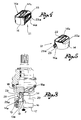
- valves shown comprise a hollow cylinder body (11) designed to be screwed into a tap (not shown) with the interpositioning of a seal (12), the tap being in line with a water delivery conduit, in the direction of the arrow (F) (Fig. 3).
- Valvular parts made up of two overlapping ceramic disks (13, 14), one below the other, are fitted in the cylinder body (11).
- the lower disk (13) is fixed inside the body (11) and is positioned, if necessary through the use of a seal (15), on an axially movable ring (16) which has a bottom seal (17).
- Said disk (13) has at least one hole (13a) for the flow of water coming from the water conduit in the direction of the arrow (F).
- the upper disk (14) rests against and rotates on the lower fixed disk (13) and has at least one hole or slot (14a) positionable in correspondence to and away from the hole (13a) of the fixed disk.
- the fixed disk and the movable disk respectively have two holes (13a) and two slots (14a), whilst in the case of valves with a 180° rotation, the fixed disk and the movable disk respectively have one hole (13a) and one slot (14a).
- the movable disk (14) is splined to an entrainer (18) which is in turn splined to a control rod (19) rotated in the body, operated by a knob (not shown) and has rotation limit stops at 90° and 180°.
- the entrainer (18) has a central bottom tab (18a) which is inserted in a slot (14b) formed on the upper surface of said disk (14).
- the entrainer (18) and/or the cylinder body (11) have lateral openings (20) at the same height of slots (14a) of the movable disk (14) and are designed for the outlet of water from the valve.
- both types of valves also have an antinoise baffle (21) made of a metal netting.
- Said baffle (21) has a transversal horizontal part (22) designed to rest against the upper surface of the movable disk (14) and to be placed between said disk and the entrainer (18).
- Said part (22) of the net type baffle (21) also has a central slot (22a) which is in correspondence to the upper slot (14b) of the disk (14) and into which the splining tab (18a) of the entrainer (18) is fitted to keep the baffle in place (Fig. 3).
- the net type baffle has one or two wings (23) which extends downwards from the horizontal part (22) and each end with a lower flap (23a) turned upwards towards the outside.
- the antinoise baffle (21) When the antinoise baffle (21) is fitted as in Fig. 3, it is blocked between the upper disk (14) and the entrainer (18) and one or each of its wings (23) orthogonally extend towards the fixed disk near to the slot or slots (14a) of the movable disk (14). The wings extending between these slots and the opening (20) for the outlet of water from the body (11).
- the wings (23) are such a length so as not to reach the lower disk (13) but to remain slightly raised from it; the flap (23a) strengthens the wings so as to prevent them from bending and also improves the validity of the baffle (21).
- this baffle does not reduce the valve flow capacity and allows for the water to flow even when dirt particles are trapped by the net.
- the net dampens water flow turbulence, prevents cavitation of the flow and notably reduces the noise of the valve as has been experimented in tests carried out during bad water flow and pressure conditions.
Landscapes
- Engineering & Computer Science (AREA)
- General Engineering & Computer Science (AREA)
- Mechanical Engineering (AREA)
- Sliding Valves (AREA)
- Domestic Plumbing Installations (AREA)
- Sealing Material Composition (AREA)
- Check Valves (AREA)
- Valve Housings (AREA)
- Gasket Seals (AREA)
- Fluid-Damping Devices (AREA)
Claims (2)
- Schalldämmender Störkörper, insbesondere für Ventile der Schraubart, die folgende Teile enthalten:- einem zylindrischen Hohlkörper (11), der in einen in Linie mit der das abzugebende Wasser heranführenden Leitung ausgerichteten Hahnkörper einzuschrauben ist, und in diesem zylindrischen Hohlkörper von unten nach oben,- einen Dichtungsring (17),- eine im Hohlkörper (11) feststehende, mit mindestens einer Durchtrittsöffnung (13a) für das Wasser versehene erste Keramikplatte (13),- eine auf der ersten Keramikplatte (13) drehbar aufliegende zweite Keramikplatte (14), die mindestens einen seitlichen Schlitz (14a) besitzt, der durch eine Viertels- oder Halbdrehung der zweiten Keramikplatte (14) in eine der ersten Keramikplatte (13) gegenüberliegende oder von dieser entfernte Stellung überführbar ist,- einen Mitnehmer (18), der drehbar im Hohlkörper (11) angeordnet ist und an der zweiten Keramikplatte (14) angreift, um sie zu drehen, und- eine zentrale Betätigungsstange (19), die mit dem Mitnehmer (18) verkeilt und mit einem von Hand betätigbaren Betätigungsknopf versehen ist, der dazu dient, die zweite Keramikplatte (14) über den Mitnehmer (18) zu steuern und zu betätigen,wobei der zylindrische Hohlkörper und/oder der Mitnehmer (18) radiale Öffnungen (20) zum Austritt des Wassers in Richtung auf eine Wasserabgabemündung und mindestens ein siebartiges Element (21) aufweisen, das an der zweiten Keramikplatte (14) angeordnet ist und dort festsitzt und das mindestens einen sich in Richtung zur ersten Keramikplatte (13) in der Nähe des einen oder aller seitlichen Schlitze (14a) der zweiten Keramikplatte (14) erstreckenden Flügel (23) aufweist, derart, daß die Flügel (23) sich zwischen dem Schlitz und der Öffnung (20) für den Austritt des Wassers erstrecken,
dadurch gekennzeichnet, daß das siebartige Element (21) eine zwischen der zweiten Keramikplatte (14) und dem Mitnehmer (18) angeordnete und dort gehaltene querverlaufende Partie besitzt und daß einer der Flügel (23) oder alle Flügel des siebartigen Elementes (21) sich von der horizontalen, querverlaufenden Partie (22) nach unten in Richtung auf die erste feststehende Keramikplatte (13) zu erstreckt bzw. erstrecken. - Schalldämpfender Störkörper nach Anspruch 1, dadurch gekennzeichnet, daß einer der Flügel (23) oder jeder Flügel des siebartigen Elementes (21) mit einem nach oben und auswärts gerichteten klappenartigen Lappen (23a) endet.
Applications Claiming Priority (2)
| Application Number | Priority Date | Filing Date | Title |
|---|---|---|---|
| IT00697690U IT223075Z2 (it) | 1990-04-24 | 1990-04-24 | Schermo antirumore particolarmente per valvole tipo vitone con tenuta a piastrine ceramiche |
| IT697690 | 1990-04-24 |
Publications (2)
| Publication Number | Publication Date |
|---|---|
| EP0454628A1 EP0454628A1 (de) | 1991-10-30 |
| EP0454628B1 true EP0454628B1 (de) | 1994-12-21 |
Family
ID=11122942
Family Applications (1)
| Application Number | Title | Priority Date | Filing Date |
|---|---|---|---|
| EP91830102A Revoked EP0454628B1 (de) | 1990-04-24 | 1991-03-14 | Geräuschabschirmung für Spindelventile mit Keramikdichtscheiben |
Country Status (10)
| Country | Link |
|---|---|
| US (1) | US5082241A (de) |
| EP (1) | EP0454628B1 (de) |
| JP (1) | JPH08815U (de) |
| AT (1) | ATE116044T1 (de) |
| AU (1) | AU7509691A (de) |
| CA (1) | CA2038231A1 (de) |
| DE (1) | DE69106034T2 (de) |
| DK (1) | DK0454628T3 (de) |
| ES (1) | ES2066410T3 (de) |
| IT (1) | IT223075Z2 (de) |
Families Citing this family (5)
| Publication number | Priority date | Publication date | Assignee | Title |
|---|---|---|---|---|
| AT403514B (de) * | 1995-02-24 | 1998-03-25 | Ideal Standard | Sanitäres wasserventil |
| DE19510289A1 (de) * | 1995-03-22 | 1996-09-26 | Grohe Armaturen Friedrich | Mengenregulierventil |
| AT404293B (de) * | 1995-09-14 | 1998-10-27 | Ideal Standard | Wasserventiloberteil mit in einem gehäuse befindlichen keramischen dichtscheiben |
| US6279605B1 (en) * | 2000-07-05 | 2001-08-28 | Shih-Ming Wang | Water stopping seat of ceramic control valve of faucet |
| US20060086923A1 (en) * | 2004-10-08 | 2006-04-27 | Marotta Controls, Inc. | Rotary valve and control system |
Family Cites Families (7)
| Publication number | Priority date | Publication date | Assignee | Title |
|---|---|---|---|---|
| AT4390B (de) * | 1900-06-21 | 1901-06-10 | Harry Bridgman Smith | |
| DE2622179C2 (de) * | 1976-05-19 | 1986-04-30 | Ideal-Standard Gmbh, 5300 Bonn | Sanitäres Wasserventil |
| DE2838195C2 (de) * | 1978-09-01 | 1985-01-31 | Hansa Metallwerke Ag, 7000 Stuttgart | Ventil |
| FR2485147A1 (fr) * | 1980-06-23 | 1981-12-24 | Pont A Mousson | Dispositif de reglage de debit pour robinet |
| DE3234643A1 (de) * | 1982-09-18 | 1984-03-22 | Ideal-Standard Gmbh, 5300 Bonn | Oberteilkartusche fuer ein sanitaeres einzel-absperrventil |
| DE3503793C2 (de) * | 1985-02-05 | 1995-09-21 | Grohe Armaturen Friedrich | Mischventil |
| US4657045A (en) * | 1985-02-06 | 1987-04-14 | Kitamuragokin Ind. Co., Ltd. | Noise-preventing structure for water mixing cocks |
-
1990
- 1990-04-24 IT IT00697690U patent/IT223075Z2/it active IP Right Grant
-
1991
- 1991-03-14 DE DE69106034T patent/DE69106034T2/de not_active Revoked
- 1991-03-14 ES ES91830102T patent/ES2066410T3/es not_active Expired - Lifetime
- 1991-03-14 EP EP91830102A patent/EP0454628B1/de not_active Revoked
- 1991-03-14 AT AT91830102T patent/ATE116044T1/de not_active IP Right Cessation
- 1991-03-14 DK DK91830102.9T patent/DK0454628T3/da active
- 1991-03-14 CA CA002038231A patent/CA2038231A1/en not_active Abandoned
- 1991-04-18 AU AU75096/91A patent/AU7509691A/en not_active Abandoned
- 1991-04-23 US US07/689,967 patent/US5082241A/en not_active Expired - Fee Related
- 1991-04-24 JP JP059314U patent/JPH08815U/ja active Pending
Also Published As
| Publication number | Publication date |
|---|---|
| US5082241A (en) | 1992-01-21 |
| IT9006976V0 (it) | 1990-04-24 |
| IT9006976U1 (it) | 1991-10-25 |
| ES2066410T3 (es) | 1995-03-01 |
| CA2038231A1 (en) | 1991-10-25 |
| IT223075Z2 (it) | 1995-06-09 |
| JPH08815U (ja) | 1996-05-21 |
| DE69106034T2 (de) | 1995-05-11 |
| ATE116044T1 (de) | 1995-01-15 |
| AU7509691A (en) | 1991-11-07 |
| EP0454628A1 (de) | 1991-10-30 |
| DK0454628T3 (da) | 1995-06-06 |
| DE69106034D1 (de) | 1995-02-02 |
Similar Documents
| Publication | Publication Date | Title |
|---|---|---|
| US5524863A (en) | Quarter turn rotatable flow control valve | |
| EP0454628B1 (de) | Geräuschabschirmung für Spindelventile mit Keramikdichtscheiben | |
| US5566711A (en) | Combined control and regulating valve for liquids or gases | |
| CN109937280B (zh) | 排水阀 | |
| US20190316708A1 (en) | Control butterfly valve | |
| US4679595A (en) | Device for controlling the flow in a pipe system | |
| US5651531A (en) | Water flow control device | |
| JPH04228733A (ja) | トイレのタンクバルブ | |
| US2638929A (en) | Self-throttling valve | |
| CN1089838C (zh) | 用于冲水箱的放水阀 | |
| JPH04248080A (ja) | 安全弁 | |
| EP0592415B1 (de) | Ventilvorrichtung | |
| EP1131575B1 (de) | Ventil | |
| US820146A (en) | Drain-valve for radiators. | |
| US4134164A (en) | Water standpipe for toilet sump tanks | |
| US4982928A (en) | Water outlet fitting with sound damper insert | |
| US5850848A (en) | Float valve | |
| JP2589804Y2 (ja) | 流体制御弁 | |
| US20190063680A1 (en) | Steam trap and aseptic double seat valve | |
| KR102656503B1 (ko) | 앵글밸브 | |
| US965343A (en) | Water-faucet. | |
| RU2029905C1 (ru) | Канализационный клапан | |
| KR100334929B1 (ko) | 스트레이너 밸브 | |
| KR102038908B1 (ko) | 캐비테이션 방지 기능을 갖는 밸브 | |
| JPH04337167A (ja) | キャビテーション抑止機能を具えたバタフライ弁 |
Legal Events
| Date | Code | Title | Description |
|---|---|---|---|
| PUAI | Public reference made under article 153(3) epc to a published international application that has entered the european phase |
Free format text: ORIGINAL CODE: 0009012 |
|
| AK | Designated contracting states |
Kind code of ref document: A1 Designated state(s): AT BE CH DE DK ES FR GB GR IT LI LU NL SE |
|
| 17P | Request for examination filed |
Effective date: 19920411 |
|
| 17Q | First examination report despatched |
Effective date: 19930802 |
|
| GRAA | (expected) grant |
Free format text: ORIGINAL CODE: 0009210 |
|
| ITF | It: translation for a ep patent filed | ||
| AK | Designated contracting states |
Kind code of ref document: B1 Designated state(s): AT BE CH DE DK ES FR GB GR IT LI LU NL SE |
|
| REF | Corresponds to: |
Ref document number: 116044 Country of ref document: AT Date of ref document: 19950115 Kind code of ref document: T |
|
| PGFP | Annual fee paid to national office [announced via postgrant information from national office to epo] |
Ref country code: GB Payment date: 19950113 Year of fee payment: 5 |
|
| PGFP | Annual fee paid to national office [announced via postgrant information from national office to epo] |
Ref country code: DK Payment date: 19950131 Year of fee payment: 5 Ref country code: BE Payment date: 19950131 Year of fee payment: 5 |
|
| PGFP | Annual fee paid to national office [announced via postgrant information from national office to epo] |
Ref country code: LU Payment date: 19950201 Year of fee payment: 5 |
|
| REF | Corresponds to: |
Ref document number: 69106034 Country of ref document: DE Date of ref document: 19950202 |
|
| ET | Fr: translation filed | ||
| PGFP | Annual fee paid to national office [announced via postgrant information from national office to epo] |
Ref country code: ES Payment date: 19950224 Year of fee payment: 5 |
|
| REG | Reference to a national code |
Ref country code: ES Ref legal event code: FG2A Ref document number: 2066410 Country of ref document: ES Kind code of ref document: T3 |
|
| PGFP | Annual fee paid to national office [announced via postgrant information from national office to epo] |
Ref country code: SE Payment date: 19950316 Year of fee payment: 5 |
|
| PGFP | Annual fee paid to national office [announced via postgrant information from national office to epo] |
Ref country code: GR Payment date: 19950322 Year of fee payment: 5 Ref country code: DE Payment date: 19950322 Year of fee payment: 5 |
|
| PGFP | Annual fee paid to national office [announced via postgrant information from national office to epo] |
Ref country code: CH Payment date: 19950328 Year of fee payment: 5 |
|
| PGFP | Annual fee paid to national office [announced via postgrant information from national office to epo] |
Ref country code: FR Payment date: 19950330 Year of fee payment: 5 Ref country code: AT Payment date: 19950330 Year of fee payment: 5 |
|
| PGFP | Annual fee paid to national office [announced via postgrant information from national office to epo] |
Ref country code: NL Payment date: 19950331 Year of fee payment: 5 |
|
| REG | Reference to a national code |
Ref country code: DK Ref legal event code: T3 |
|
| PLBI | Opposition filed |
Free format text: ORIGINAL CODE: 0009260 |
|
| 26 | Opposition filed |
Opponent name: HANSA METALLWERKE AG Effective date: 19950918 |
|
| NLR1 | Nl: opposition has been filed with the epo |
Opponent name: HANSA METALLWERKE AG |
|
| PLBF | Reply of patent proprietor to notice(s) of opposition |
Free format text: ORIGINAL CODE: EPIDOS OBSO |
|
| PG25 | Lapsed in a contracting state [announced via postgrant information from national office to epo] |
Ref country code: LU Free format text: LAPSE BECAUSE OF NON-PAYMENT OF DUE FEES Effective date: 19960314 |
|
| PG25 | Lapsed in a contracting state [announced via postgrant information from national office to epo] |
Ref country code: ES Free format text: LAPSE BECAUSE OF NON-PAYMENT OF DUE FEES Effective date: 19960315 |
|
| PLBF | Reply of patent proprietor to notice(s) of opposition |
Free format text: ORIGINAL CODE: EPIDOS OBSO |
|
| REG | Reference to a national code |
Ref country code: DK Ref legal event code: EBP |
|
| RDAG | Patent revoked |
Free format text: ORIGINAL CODE: 0009271 |
|
| STAA | Information on the status of an ep patent application or granted ep patent |
Free format text: STATUS: PATENT REVOKED |
|
| REG | Reference to a national code |
Ref country code: CH Ref legal event code: PL |
|
| GBPR | Gb: patent revoked under art. 102 of the ep convention designating the uk as contracting state |
Free format text: 960427 |
|
| 27W | Patent revoked |
Effective date: 19960427 |
|
| REG | Reference to a national code |
Ref country code: GR Ref legal event code: MF4A Free format text: 3014714 |
|
| NLR2 | Nl: decision of opposition |