EP0454553A1 - Vorrichtung und entsprechende Klemme für hämostatische Sterilisation - Google Patents
Vorrichtung und entsprechende Klemme für hämostatische Sterilisation Download PDFInfo
- Publication number
- EP0454553A1 EP0454553A1 EP91401053A EP91401053A EP0454553A1 EP 0454553 A1 EP0454553 A1 EP 0454553A1 EP 91401053 A EP91401053 A EP 91401053A EP 91401053 A EP91401053 A EP 91401053A EP 0454553 A1 EP0454553 A1 EP 0454553A1
- Authority
- EP
- European Patent Office
- Prior art keywords
- clip
- handle
- arms
- pusher
- intended
- Prior art date
- Legal status (The legal status is an assumption and is not a legal conclusion. Google has not performed a legal analysis and makes no representation as to the accuracy of the status listed.)
- Withdrawn
Links
Images
Classifications
-
- A—HUMAN NECESSITIES
- A61—MEDICAL OR VETERINARY SCIENCE; HYGIENE
- A61F—FILTERS IMPLANTABLE INTO BLOOD VESSELS; PROSTHESES; DEVICES PROVIDING PATENCY TO, OR PREVENTING COLLAPSING OF, TUBULAR STRUCTURES OF THE BODY, e.g. STENTS; ORTHOPAEDIC, NURSING OR CONTRACEPTIVE DEVICES; FOMENTATION; TREATMENT OR PROTECTION OF EYES OR EARS; BANDAGES, DRESSINGS OR ABSORBENT PADS; FIRST-AID KITS
- A61F6/00—Contraceptive devices; Pessaries; Applicators therefor
- A61F6/20—Vas deferens occluders; Fallopian occluders
- A61F6/202—Means specially adapted for ligaturing, compressing or clamping of oviduct or vas deferens
- A61F6/204—Clamp applying devices
-
- A—HUMAN NECESSITIES
- A61—MEDICAL OR VETERINARY SCIENCE; HYGIENE
- A61D—VETERINARY INSTRUMENTS, IMPLEMENTS, TOOLS, OR METHODS
- A61D1/00—Surgical instruments for veterinary use
- A61D1/06—Castrating appliances
Definitions
- the present invention relates to the veterinary field; it relates more particularly to a material intended for sterilization by ischemia of female animals.
- the sterilization of female animals can have many advantages.
- the modification of the hormonal cycles, linked to this sterilization makes it possible to improve the quantities and qualities of the meat, thereby bringing significant economic value.
- Weight gains can thus be of the order of 7 to 8%; sterilization also makes it possible to orient the animal's metabolisms towards a redder, more tender, low-fat and more tasty meat.
- the technician operates blind, either by the flanks after skin incision, or, preferably, because it is faster and easier, by the vaginal route, after perforation of the vaginal wall.
- the operator introduces one of his hands to the ovaries and the operating material is introduced simultaneously or later; this material is suitable for almost blind work, with one hand. In all cases, and for reasons of aseptia, we strive to minimize penetration to the organ to be operated, under penalty of increasing the risk of infection.
- the crushers techniques or the techniques of ovariectomy which consist of an excision of the ovary, are difficult to carry out and they are often long and stressful for the animal. These techniques also present the conventional risks of an operational accident, such as hemorrhages, linked to any surgical intervention.
- the equipment used for this type of operation such as that described in document AU-B-28200/77, is often heavy and unwieldy; it must be sterilized between each operation to avoid the risk of infection.
- DEGIVE rings which rings consist of a rubber ring threaded on a bead hollowed out with a conical hole. After perforation of the vaginal wall, the ring is placed around the ovarian pedicle and it is tightened on the latter by means of the pearl to achieve ischemia by ligation.
- This work is done with one hand, blind.
- the operator grasps the ring between three fingers, outside, it keeps it in tension and introduces it through the vulva of the animal.
- a cord which passes through the rear loop of the ring, allows, by pulling from the outside with your free hand, to facilitate tightening by means of the bead.
- This technique is very delicate to perform; it also presents risks of infection, and in particular of peritonitis, linked in particular to the handling of the non-sterile operating cord, which passes through the vulva, often soiled with excrement, and through the abdominal cavity.
- the invention aims to overcome these various drawbacks and it provides ischemia sterilization equipment offering good guarantees of effectiveness and significantly reducing the problems of aseptic and hemorrhagic risks associated with prior techniques.
- the structural characteristics of the material make it simple to build, light, handy and space-saving. This material can be used with the minimum number of external aid personnel, it can very advantageously be sterile and be for single use to suppress disinfection between each animal; this single use also makes it possible to eliminate the problems of transmission of certain viral diseases by blood (leukosis, IPR, PVD ).
- the female animal sterilization material comprises clip-shaped means for pinching off all of the blood pathways which supply blood to the ovaries. It also includes an instrument for installing the clip, provided, at one of its ends with an operating head intended to be taken by one of the operator's hands, in situ, and, at its other end, with means of remote operation of the clip, operated by the other hand of the operator, from the outside. Still according to the invention, the clip consists of two pinching arms connected to one another at one of their ends by a hinge, and provided at their other end with fastening means intended to keep said clip in the closed clamping position.
- the clip is associated with a delivery instrument comprising an elongated support in the form of a handle, provided at one of its ends with means for holding the clip in the open position, ready to be positioned around the ovarian pedicle.
- This handle has a length L adapted to allow the operator to maneuver from the outside, to bring the clip to the ovaries and in particular to the ovarian pedicles to be treated.
- the head of the elongated handle defines an end-shaped bulge Vé, which Vé consists of two divergent lateral extensions which each hold an arm of the clip.
- Vé consists of two divergent lateral extensions which each hold an arm of the clip.
- the elongated handle is hollow and contains a pusher, controlled from the outside, capable of at least initiating the positioning of the clip on the organ to be treated.
- the lateral extensions which define the head of the handle include pairs of lips which extend the internal cavity of said handle and which serve as a guide member and for embedding the arms of the clip.
- the end of these extensions is provided with cam-shaped guides which are used to control the closing of the arms of the clip controlled by the pusher.
- the pusher is controlled from the outside, by means of a projecting trigger arranged at the end of the handle opposite the clip support head.
- This trigger cooperates with a gripping system, in the form of a fixed stop on the handle, for one-handed operation by the operator.
- the support handle can advantageously be associated with two clips positioned one behind the other and both slaved to the pusher. This characteristic allows the treatment of the two glands, successively, without having to bring out the material and the surgical arm.
- the pusher preferably comprises a two-position operating trigger, associated with non-return means of the pusher relative to the handle.
- the handle and the associated clip or clips are produced by molding of biocompatible plastic material of the PVC type; the handle length is around 30 to 80 cm.
- the clip support can also be associated with a perforator intended for example for puncturing the vaginal wall. This perforator is preferably removable and it covers the end of the handle.
- the equipment can also advantageously be provided with a complementary lip, molded inside the support and serving as a safety catch for the movement of the pusher; the elongated, rigid support makes it possible to position the operating means in the form of clips, at will, by guiding and maneuvering, with the free hand, from the outside; the progression and the maneuver of the operating hand, in situ, are thereby facilitated.
- This new technique is easier to implement and simpler than the previous techniques, it is also more reliable and limits the risks of infection.
- the invention also relates to a clip intended in particular but not exclusively to be adapted on the sleeve-shaped laying instrument and which allows sterilization of female animals by pinching the ovarian pedicle.
- the clip includes clamping arms connected together by a hinge and provided, at their other end, with fastening means intended to keep them in the closed clamping position.
- the clip also includes, at each of its ends, means in the form of walls intended to form, with the arms, an enclosed space in which the tissues are trapped before pinching.
- the clip comprises a flexible hinge in the form of a ring which connects one of the ends of the two arms; this joint is associated with a tissue blocking tab and, optionally, elastic return.
- the other end of these arms is provided, for one, with male appendages, and for the other, female notches, intended to obtain a plurality of securing notches.
- These securing means are intended to keep the clip in the closed clamping position.
- This clamping is adjustable and can be adapted to the different sizes of ovaries to be treated.
- the middle zone of these securing means is provided with complementary male and female elements which avoid the lateral offset of the arms relative to one another.
- the internal faces facing the arms of the clip are notched transversely; one of these faces has a longitudinal bar which projects and which cooperates with a longitudinal notch provided in the other face to form a baffle.
- the internal face of one of the pinching arms comprises means for trapping and blocking the progression of the tissues during the pinching.
- These means are in the form of a stop protruding towards the homologous arm; this stop is disposed slightly upstream of the end securing means and it cooperates with a reservation of complementary shape made in the homologous arm to allow closing.
- the stop has a triangular shape; its rear face is intended for blocking the tissues and its front face comprises two lateral lips which define a channel in which a median lip is fitted, provided in its homologous reservation, when the arms are tightened.
- the free ends of the arms of the clip include protruding pins which are intended to cooperate with grooves provided in the support handle and in its two end extensions, for guiding said clip controlled by the positioning pusher.
- the rear part of the clip is also provided with an appendix, disposed at the joint; this protruding appendage allows, on the one hand, the guidance of the rear of the clip in a groove provided inside the handle, and, on the other hand, the positioning of the clip between two lateral stops provided at the end of the pusher.
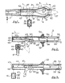
- the device according to the invention consists of an elongated support 1 in the form of a rigid handle which is provided, at one of its ends, with means for holding and positioning two clips 2 ′, 2 ⁇ shown in dotted lines.
- the front part of the handle 1 is shown in Figure 1; the figure 2 shows its rear part.
- the length L of the handle 1 must allow an operator to bring, from the outside, the clip or clips 2 ′, 2 ⁇ to the ovaries to be treated, by the vaginal route or by the sides.
- the handle 1 can have a length of the order of 30 to 80 cm, preferably 50 to 70 cm.
- the material shown consists of a hollow handle whose rear part has a substantially rectangular shape and whose front part gradually widens to determine an end bulge.
- this front part is V-shaped consisting of two divergent lateral extensions 3 and 4 which define a shaped space according to the structure of the clip 2 ′, 2 ⁇ to be received.
- the support 1 is preferably made by molding of biocompatible plastic material of the PVC type; it is preferably obtained by assembling two homologous half-shells.
- the internal cavity of the handle 1 contains a longitudinal pusher 5 guided by the walls of the handle and / or by means of internal grooves.
- the sliding pusher 5 is associated with trigger-shaped control means 6 which ensures its longitudinal movement inside the handle and which will be detailed below.
- the pusher 5 acts on the base of the clip (s) 2 and allows them to exit from the support handle 1 to allow their positioning on the member to be treated.
- the movement of the clip (s) 2 ', 2' is also controlled by guide means provided at the front part of the handle 1 so as to ensure correct and easy positioning on the organ to be treated. These guide means will be detailed later.
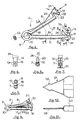
- FIG. 4 to 9 An exemplary embodiment of a clip 2 intended to be mounted on the handle 1 is shown in Figures 4 to 9.
- This clip 2 defines a jaw consisting of two clamping arms, or jaws 7 and 8, connected together, to one of their ends, by means of a joint 9; its structure is particularly suited to its laying function on the ovarian pedicle via a handle support.
- the clip 2 is advantageously made of biocompatible plastic material such as PVC in a single piece.
- the joint 9 is obtained by forming an open loop; the structure of the clip and the nature of the material used make this joint flexible. In the rest position, the arms 7 and 8 diverge from the articulation 9 and the clip 2 is open.
- a monobloc tongue 10 is fitted on the articulation 9 to close the space between the arms 7 and 8 and block the progression of the tissues on this side; the tongue 10 also serves as an elastic return means in the case where the flexibility of the joint 9 is not sufficient.
- the free end of the arms 7 and 8 comprises securing means intended to hold the clip in the closed position, that is to say in the clamping position.
- the arm 7 is extended by a lug 11 which extends substantially at right angles to the homologous arm 8.
- This lug 11 is provided with a set of internal female notches 12 which, in the example shown, are among the number of of them.
- the female notches 12 are intended to cooperate with the male appendages 13 shaped at the end of the arm 8. These appendages 13, also two in number, are arranged on a tab 14 which extends at right angles, towards the outside, opposite the homologous arm 7.
- the appendages 13 are oriented in the direction of the axis of the arm 8 and are intended to engage in the female orifices 12 of the tab 11 to serve as means of closing the clip 2 This closure is obtained by bringing the two arms 7 and 8 closer together; the plurality of female notches 12 and male appendages 13 makes it possible to obtain an adjustable fastening, in the form of notches, for adapting the clip according to the thickness of the ovarian pedicle to be treated.
- the number and the shape of the notches can vary according to the desired settings in particular.
- the tab 11 which extends at right angles to the end of the arm 7 also comprises, FIGS. 4 and 7, two median lips 15 which extend transversely to the female notches 12. These median lips 15 are intended to cooperate, during the closure of the clip, with a central reservation 16 provided on the corresponding face of the homologous tab 14. The penetration of the lips 15 into the reservation 16 confirms the positioning of the two arms 7 and 8 relative to each other and in particular avoids their lateral offset when significant gripping forces are subjected to them.
- Closing the clip 2 brings the two arms 7 and 8 closer together, the internal faces of which come to be positioned one against the other or close to one another.
- the internal faces of each arm 7 and 8 opposite are notched and thus comprise a series of transverse notches 17 which define a series of alternating male and female parts. These male and female parts are offset from one arm to the other so that the male parts of one arm cooperate with the female parts of the other arm. In the clamping position, a joint plane in the form of a broken line is thus produced.
- the internal face of the arm 8 further comprises a longitudinal bar 18, projecting, disposed substantially on the median of said face.
- This bar 18 is intended to come to be embedded in a longitudinal notch 19 provided in the corresponding internal face of the arm 7 to form a baffle.
- This particular structure allows a double rupture of the blood circulation at the level of the ovarian pedicle. This characteristic makes it possible to improve the pinching quality of the arms and completes the aforementioned means 15 and 16 which avoid the lateral offset of said arms relative to each other.
- the longitudinal bar 18 has a height which increases slightly from front to rear. The difference of height from one end point to the other is around 2 / 10ths of a mm.
- This characteristic makes it possible to improve the pinching on the organ to be treated, at the rear zone of the clip, that is to say on the side of the joint, which zone tends to reopen slightly when the arm 8 bends under the effect of the thickness of the crushed ovarian pedicle, when the forceps are closed.
- the internal face of the arm 7 also includes a stop 20 which projects towards the homologous arm 8.
- This stop 20 has a substantially triangular shape and it is disposed slightly upstream of the end tab 11. It has a rear face 21 which extends substantially perpendicularly to the arm 7 and an inclined front face 22 which extends to the base of the tab 11. As can be seen in FIG. 8, the stop 20 does not extend over the entire width arm 7; its width is around a third of that of the arm 7; it is arranged on this arm in a middle position.
- the homologous arm 8 has a reservation 23 of triangular complementary shape intended for the embedding of the stop 20 during tightening.
- the stop 20 has a height which corresponds substantially to the width of the arm 7, that is to say of the order of 6 mm; it avoids the progression of the tissues towards the end of the clip when tightening the arms. This effect is shown diagrammatically in FIG. 9.
- the stop 20 has dimensions such that its upper end arrives substantially at the level of the internal face of the arm 8, just before the first locking notch.
- the internal faces of the two arms 7 and 8, associated with the rear face 21 of the abutment 20, thus define a closed space from which the tissues of the ovarian pedicle cannot escape. This avoids the possible risks of eviction of part of the tissue outside the clip tightening zone, risks which would allow the blood supply to the ovaries to continue.
- the front face 22 of the stop 20 also includes two lateral lips 26, visible in FIGS. 4 and 8. These two lips 26 define a channel 27 in which will come to embed a middle lip 28 provided on the corresponding face of the reservation 23. This characteristic further improves the positioning and centering of the arms 7 and 8 relative to each other.
- the nature of the material used and the structure of the clip are adapted to ensure easy and effective positioning of the clip on the ovarian pedicle to be treated.
- the tab 11 disposed at the end of the arm 7 has a slight flexibility in the median plane of the clip; this characteristic facilitates the embedding of the male members 13 in the form of hooks.
- the corresponding part of the arm 8 is stiffened by means of reinforcing ribs 29 which make it possible to improve the holding of the tab 14.
- the free ends of the arms 7 and 8 also include lateral pins 31, arranged at the respective external ends of the legs 11 and 14. These one-piece pins 31 protrude laterally relative to the clip, seen from the front (FIGS. 6, 7 and 8); they are intended to be positioned in grooves made in the internal face of the support handle 1 to correctly guide the clip during its progression at the end of said handle.
- the base of the clip also includes an end appendage 32 which projects, on the one hand, laterally with respect to the plane of the arms 7 and 8 and, on the other hand, towards the rear with respect to the articulation 9.
- This appendage 32 is intended to be fitted into a corresponding groove made on one of the internal faces of the handle 1, for guiding the rear part of the clip 2 during its progression; this appendix is also used for positioning the base of the clip 2 on the end of the pusher 5.
- the arms 7 and 8 can have a length of the order of 5 to 8 cm, a width of 0.5 to 1 cm and a thickness of the order of 0.5 cm.
- the support 1 contains, at the rear, the pusher 5 intended to act on the two clips 2 ′, 2 ⁇ arranged one after the other, in the front part.
- This front end is adapted to at least initiate the positioning of the clips on the ovarian pedicle to be treated.
- the lateral extensions 3 and 4 each have pairs of guide lips 34, directed inwards. These pairs of lips extend the cavity of the handle and extend to the ends of said extensions 3 and 4.
- the first clip 2 ′ is positioned inside the handle 1, in abutment on the pusher 5.
- the second clip 2 ⁇ is ready to be used; it is housed in the Vee carrier defined by the two lateral extensions 3, 4; it is held in place by the guide lips 34 and its base is supported on the front end of the first clip 2 ′.
- the clips 2 ′ and 2 ⁇ are slaved to the movement of the sliding plunger 5 and their guidance in the support 1 is carried out, on the one hand, by means of their end pins 31 which are embedded in corresponding grooves 35 and 36 and, on the other hand, by means of the rear appendage 32, which itself fits into an appropriate internal groove 37.
- This rear appendage 32 also allows the positioning of the clip 2 ⁇ on the pusher 5, between the two lateral end stops 38, as well as the positioning of the front clip 2 ⁇ on the end of the arm 8 of the rear clip 2 ′, by fitting between the male notches 13.
- the guide grooves 35, 36 and 37 extend over the entire length of the travel of the clips 2 ′ and 2 ⁇ , between the end of the pusher 5, as positioned in FIG. 1, and the front end of the handle 1. These grooves follow paths determined as a function of the relative movement of the arms 7 and 8 which it is desired to obtain.
- the groove 37 which guides the base of the clips 2 ′ and 2 ⁇ , is arranged substantially in the axis of the end Vee; it is straight and stops at the base of the Vee carrier.
- the two grooves 35 and 36 are arranged on each side of the groove 37 and follow a substantially symmetrical course.
- These two grooves are substantially parallel to the base of the carrier Vee; from this level they begin to diverge to reach a maximum appreciably at the level of 3/4 of the length of the lateral extensions 3 and 4; they then converge to the corresponding ends of the handle 1.
- These ends define guides 40 in the form of cams which allow the arms of the clips to be brought together, at the end of the stroke.
- Guides 40 are adapted to the shapes and dimensions of the clips; they can, as the case may be, allow these clips to be closed simply at the first notch by the sole action of the pusher 5, or achieve complete tightening immediately. The complete and final closure of the clip can be carried out manually, by the operator, with his hand located inside.
- the embodiment shown shows two clips 2 ′ and 2 ⁇ positioned one behind the other and both slaved to the pusher 5; there is thus, in a single introduction of the handle, all the material necessary for the treatment of the two ovaries.
- the push-button 5 controls by sliding the movement and the fitting of the end clips.
- This pusher is itself guided in the body of the handle, at the front, by means of lateral extensions 42 which come into abutment with a slight play on the wall of the handle 1 and, at the rear, via an end guide 43 which slides in a longitudinal groove 44 arranged in the side walls of said handle
- the pusher 5 Before use, the pusher 5 is positioned completely at the rear of the handle 1, in abutment on its base 45.
- the support 1 may advantageously include a cooperating integral lip or tongue 46 with the guide 43 and acting as a safety catch to prevent the involuntary movement of the pusher 5 and the exit of the end clip. This lip 46 is produced so as to be able to be broken by the guide 43 during a voluntary push on the pusher 5.
- the movement of the pusher 5 is controlled by means of a trigger 6 active at its rear end and which projects beyond the support, by a longitudinal orifice 48.
- the trigger 6 is movable relative to push button 5; it comprises lugs 49 arranged on either side of the central core of said pusher 5 and which bear on a ramp 50 shaped at the rear part of the pusher 5 and which allow its guidance on said pusher.
- the trigger 6 In the standby position for fitting the first clip 2 ⁇ , the trigger 6 is positioned at the rear end of the longitudinal orifice 48; its front part 51 is in abutment on a square return 52 shaped on the pusher 5 (FIG. 2). It is noted that a displacement towards the front of the trigger 6 with respect to the handle 1 achieves the sliding towards the front of the pusher 5.
- the length of the opening 48 through which the trigger 6 passes corresponds to a stroke of the pusher 5 which allows the installation of a clip on the organ to be treated.
- the pusher 5 comprises non-return means in the form of lips 54 arranged in an appropriate manner along its length. These lips 54 are intended to cooperate with stops 55 provided in the cavity of the handle so as to avoid a backward movement of the pusher 5 once the first clip 2 ⁇ placed.
- This non-return position is shown in Figure 3.
- the flexibility of the lips 54 suitably oriented, allows their passage on the stops 55 but once passed they prevent the return of the pusher to the rear.
- the trigger 6 has reached the end of its travel and can then be brought back by sliding the lugs 49 on the ramp 50. As can be seen in Figures 2 and 3, the ramp 50 rises rearward, and, when the trigger slides, causes the latter to tilt which can thus cross, slightly by force, the second return square 56 provided on the pusher.
- This return 56 serves as a second stop for the front part 51 of the trigger 6 and the latter will be able to start its cycle again for the positioning of the second clip 2 ′.
- the support 1 can advantageously be associated with a perforator 57 shown in FIG. 10 and in dotted lines in FIG. 1.
- This perforator 57 consists of a simple molded plastic part, constituted a blade 58 provided with cutting edges, mounted on a cover 59. It is fitted, like a cap, on the lateral ends 3 and 4 of the handle 1.
- the sterilization operation is carried out by the sides of the animal, by means of a scalpel, or by the vaginal route by puncturing the vaginal wall with the perforator 57.
- the penetration of the operator's hand is performed simultaneously or a little before the introduction of the clip 2 associated with its support handle 1, which is guided from the outside by the free hand of the technician.
- the equipment is then in the position shown in Figures 1 and 2; the pusher 5 and the control trigger 6 are in their maximum rear position.
- the rear clip 2 ′ is arranged in the support 1; its lateral pins 31 are positioned in the corresponding grooves 35 and 36 and its rear end appendage is embedded on the one hand, in the groove 37 and, on the other hand, between the two stops 38 of the pusher 5.
- the front clip 2 ⁇ is positioned in the Vee carrier; each of its gripping arms 7 and 8 is embedded in one of the lateral extensions 3 and 4 and the jaw is in a position of maximum opening.
- the pins 31 of the clip 2 ⁇ are embedded in the grooves 35 and 36, at the point of maximum divergence of the latter.
- the operator After identifying and seizing the ovary to be treated, the operator positions the handle 1 so that the arms of the first clip 2 ⁇ enclose the ovarian pedicle. The operator can then, with his free external hand, actuate the pusher 5 by means of the trigger 6 after having forced the safety lip 46. This maneuver causes the clip 2 ⁇ to progress towards the end of the support 1 and the approximation progressive of the two pinching arms by means of grooves 35 and 36 which converge and which follow the end guides 40. The "automatic" closing of the clip can, by this operation, be carried out either on the two notches, or simply on the first. When the trigger 6 reaches the end of its travel, the lips 54 of the pusher pass the stops 55 and the first clip 2 ⁇ emerges from the handle. The operator positions the trigger 6 on the second stop 56; the second clip 2 ′ is in the waiting position in the Vee carrier, its pinching arms are open and it can be placed on the second ovarian pedicle according to a similar operation.
- the installation can be completed by hand, depending on the size of the ovary, to cause ischemia in its irrigation channels.
- a hemispherical opening 62 produced at one of the lateral extensions 3, 4 can be provided to allow the operator to define the position of the clip 2 at the end of the handle 1.
- the clips 2 ′ and 2 ⁇ and their support 1 are made of an easily sterilizable plastic material.
- the material will preferably be made available to users in a sterile bag and will preferably be for single use.
Landscapes
- Health & Medical Sciences (AREA)
- Veterinary Medicine (AREA)
- Life Sciences & Earth Sciences (AREA)
- Public Health (AREA)
- Engineering & Computer Science (AREA)
- Animal Behavior & Ethology (AREA)
- General Health & Medical Sciences (AREA)
- Wood Science & Technology (AREA)
- Zoology (AREA)
- Surgery (AREA)
- Reproductive Health (AREA)
- Biomedical Technology (AREA)
- Heart & Thoracic Surgery (AREA)
- Vascular Medicine (AREA)
- Surgical Instruments (AREA)
Applications Claiming Priority (2)
| Application Number | Priority Date | Filing Date | Title |
|---|---|---|---|
| FR9005499A FR2661327A1 (fr) | 1990-04-25 | 1990-04-25 | Materiel de sterilisation d'animal femelle par ischemie. |
| FR9005499 | 1990-04-25 |
Publications (1)
| Publication Number | Publication Date |
|---|---|
| EP0454553A1 true EP0454553A1 (de) | 1991-10-30 |
Family
ID=9396236
Family Applications (1)
| Application Number | Title | Priority Date | Filing Date |
|---|---|---|---|
| EP91401053A Withdrawn EP0454553A1 (de) | 1990-04-25 | 1991-04-19 | Vorrichtung und entsprechende Klemme für hämostatische Sterilisation |
Country Status (2)
| Country | Link |
|---|---|
| EP (1) | EP0454553A1 (de) |
| FR (1) | FR2661327A1 (de) |
Cited By (1)
| Publication number | Priority date | Publication date | Assignee | Title |
|---|---|---|---|---|
| RU203141U1 (ru) * | 2020-07-03 | 2021-03-23 | Андрей Владимирович Бубнов | Вагинальное кольцевое устройство для диагностики и лечения болезней самок сельскохозяйственных животных |
Citations (10)
| Publication number | Priority date | Publication date | Assignee | Title |
|---|---|---|---|---|
| GB1020821A (en) * | 1962-07-02 | 1966-02-23 | Eugene Robert Hustin | Device for removing glandular body parts of animals |
| US3827277A (en) * | 1969-07-29 | 1974-08-06 | Ici Ltd | Applicator for surgical clips |
| GB2025511A (en) * | 1978-07-17 | 1980-01-23 | Hollister Inc | Clamp |
| WO1980001752A1 (en) * | 1979-02-28 | 1980-09-04 | H Leveen | Blood vessel clamp |
| AU513047B2 (en) * | 1977-06-27 | 1980-11-13 | Knight, Desmond William | Bovine ovary extractor |
| GB2054384A (en) * | 1979-07-27 | 1981-02-18 | Trewavis Surgical Scient Inst | Clip applicator |
| EP0106748A1 (de) * | 1982-09-30 | 1984-04-25 | United States Surgical Corporation | Vorrichtung zum Anbringen von Klammern mit festen Backen |
| EP0128011A1 (de) * | 1983-06-01 | 1984-12-12 | Ethicon, Inc. | Blutgefässklemme mit Schneideinrichtung |
| WO1986002541A1 (en) * | 1984-10-29 | 1986-05-09 | Mattson Philip D | Surgical instrument for severing and clamping an umbilical cord |
| US4800879A (en) * | 1987-07-09 | 1989-01-31 | Vladimir Golyakhovsky | Disposable vascular occluder |
-
1990
- 1990-04-25 FR FR9005499A patent/FR2661327A1/fr not_active Withdrawn
-
1991
- 1991-04-19 EP EP91401053A patent/EP0454553A1/de not_active Withdrawn
Patent Citations (10)
| Publication number | Priority date | Publication date | Assignee | Title |
|---|---|---|---|---|
| GB1020821A (en) * | 1962-07-02 | 1966-02-23 | Eugene Robert Hustin | Device for removing glandular body parts of animals |
| US3827277A (en) * | 1969-07-29 | 1974-08-06 | Ici Ltd | Applicator for surgical clips |
| AU513047B2 (en) * | 1977-06-27 | 1980-11-13 | Knight, Desmond William | Bovine ovary extractor |
| GB2025511A (en) * | 1978-07-17 | 1980-01-23 | Hollister Inc | Clamp |
| WO1980001752A1 (en) * | 1979-02-28 | 1980-09-04 | H Leveen | Blood vessel clamp |
| GB2054384A (en) * | 1979-07-27 | 1981-02-18 | Trewavis Surgical Scient Inst | Clip applicator |
| EP0106748A1 (de) * | 1982-09-30 | 1984-04-25 | United States Surgical Corporation | Vorrichtung zum Anbringen von Klammern mit festen Backen |
| EP0128011A1 (de) * | 1983-06-01 | 1984-12-12 | Ethicon, Inc. | Blutgefässklemme mit Schneideinrichtung |
| WO1986002541A1 (en) * | 1984-10-29 | 1986-05-09 | Mattson Philip D | Surgical instrument for severing and clamping an umbilical cord |
| US4800879A (en) * | 1987-07-09 | 1989-01-31 | Vladimir Golyakhovsky | Disposable vascular occluder |
Cited By (1)
| Publication number | Priority date | Publication date | Assignee | Title |
|---|---|---|---|---|
| RU203141U1 (ru) * | 2020-07-03 | 2021-03-23 | Андрей Владимирович Бубнов | Вагинальное кольцевое устройство для диагностики и лечения болезней самок сельскохозяйственных животных |
Also Published As
| Publication number | Publication date |
|---|---|
| FR2661327A1 (fr) | 1991-10-31 |
Similar Documents
| Publication | Publication Date | Title |
|---|---|---|
| EP0621007B1 (de) | Abbindungs-und/oder Nähsystem für die endoskopische Chirurgie | |
| EP0369324B1 (de) | Chirurgisches Instrument | |
| EP2345377B1 (de) | Vorrichtung zum abbinden anatomischer Strukturen | |
| EP2999416B1 (de) | Instrument zur modifizierung des volumens von des magens eines patienten | |
| EP1815800B1 (de) | Chirurgisches Instrument zum Fixieren von weichem Gewebe | |
| EP1248567B1 (de) | Perkutane vorrichtung zur behandlung von stressbedingter harninkontinenz bei frauen mit suburethralen streifen | |
| EP0077277A1 (de) | Verfahren und Vorrichtung zur Anbringung von Blutgefässklammern und Blutgefässklammern dafür | |
| FR2804010A1 (fr) | Dispositif percutane pour le traitement de l'incontinence urinaire d'effort de la femme par bandelette sous uretrale | |
| FR2465465A1 (fr) | Instrument pour l'implantation de cheveux | |
| FR2470606A1 (fr) | Dispositif perfectionne de perforation de veine | |
| EP1014892B1 (de) | Vorrichtung zum ergreifen einer gerissenen sehne | |
| EP3256055A2 (de) | Chirurgische klammer mit zwei beweglichen armen, die durch einen querverbindungsbereich verbunden sind | |
| US20060282102A1 (en) | Method and apparatus for holding suture ends to facilitate tying of knots | |
| FR2827756A1 (fr) | Lacs perfectionne et applicateurs associes utilisables en chirurgie endoscopique | |
| FR3077465A1 (fr) | Procede et dispositif de liage de plants, son sous-ensemble d’alimentation et son lien de fixation | |
| EP1778097B1 (de) | Parietales verankerungswerkzeug und vorrichtung, insbesondere für laparoskopische und coloskopische chirurgie | |
| EP0454553A1 (de) | Vorrichtung und entsprechende Klemme für hämostatische Sterilisation | |
| EP1164957A1 (de) | Bipolare zange für pelviskopie | |
| FR2511600A1 (fr) | Dispositif de guidage pour faciliter l'introduction d'un catheter | |
| FR2644056A1 (fr) | Pince a clamper (chirurgicale) | |
| WO2002096303A1 (fr) | Dispositif atraumatique pour interventions chirurgicales sur des organes du corps humain | |
| FR2608040A1 (fr) | Instrument chirurgical pour chaponner les volailles | |
| FR2727617A1 (fr) | Dispositif d'eveinage pour realiser l'ablation d'une veine par invagination | |
| EP0516494A1 (de) | Miniaturisierte Zange als chirurgisches Instrument für Coeliochirurgie | |
| FR2744355A1 (fr) | Pince chirurgicale pour l'implantation de greffons dans un site cutane |
Legal Events
| Date | Code | Title | Description |
|---|---|---|---|
| PUAI | Public reference made under article 153(3) epc to a published international application that has entered the european phase |
Free format text: ORIGINAL CODE: 0009012 |
|
| AK | Designated contracting states |
Kind code of ref document: A1 Designated state(s): AT BE CH DE DK ES FR GB GR IT LI LU NL SE |
|
| 17P | Request for examination filed |
Effective date: 19920416 |
|
| 17Q | First examination report despatched |
Effective date: 19931028 |
|
| STAA | Information on the status of an ep patent application or granted ep patent |
Free format text: STATUS: THE APPLICATION IS DEEMED TO BE WITHDRAWN |
|
| 18D | Application deemed to be withdrawn |
Effective date: 19940308 |